
TL;DR
- Cave-ins kill faster than any other excavation hazard. A single cubic metre of soil weighs roughly 1,400 kg — collapse gives workers zero reaction time, and fatality rates in unprotected trenches remain among the highest in construction.
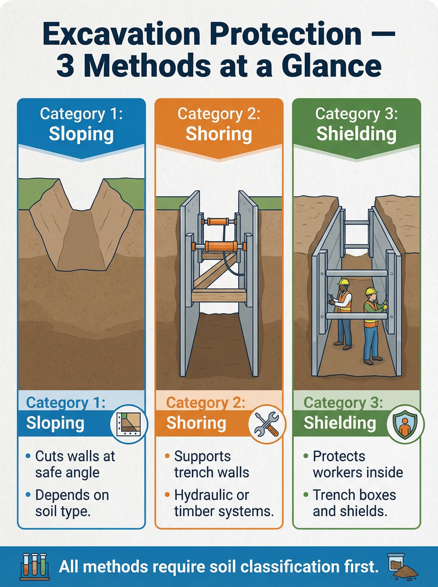
- Three primary protection methods exist: sloping, shoring, and shielding. Each method suits different soil types, trench depths, site constraints, and project timelines — choosing wrong is as dangerous as choosing nothing.
- Soil classification drives every decision. No protection method can be selected, designed, or installed without a competent person first classifying the soil and reassessing it as conditions change.
- OSHA mandates protection at 5 feet (1.5 m) depth. Any excavation deeper than this threshold requires an engineered protective system — no exceptions, no shortcuts, no “we’ll be quick” rationalizations.
- Most excavation fatalities trace back to skipped basics. Failures in soil assessment, inadequate daily inspections, improper installation, and pressure to “just get it done” kill more workers than engineering limitations ever will.
When the Trench Looks Fine — Until It Isn’t
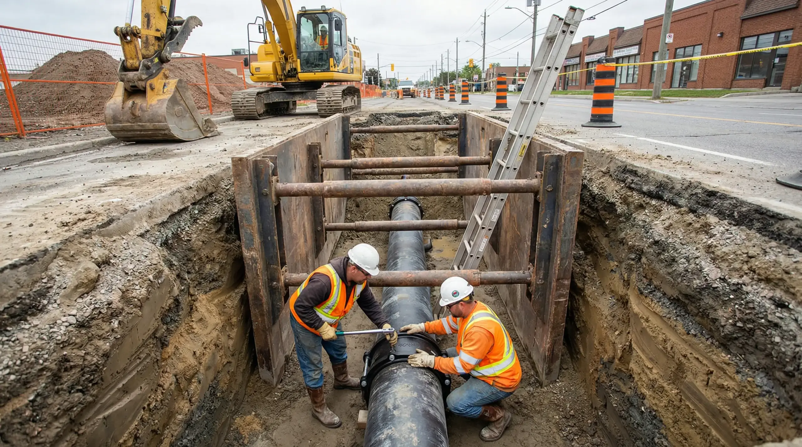
I was called to a utility installation project in the American Midwest where a three-metre trench had been open for two days with no protective system in place. The foreman’s reasoning was simple: “The walls are standing on their own.” He pointed at the clean vertical cuts like they were proof of stability. Forty minutes into my site walk, a section of the south wall calved off without warning — roughly two tonnes of clay slumping into the trench floor exactly where a pipe fitter had been working fifteen minutes earlier. Nobody was injured that day. But nobody should have needed luck to survive a workday, either.
Excavation cave-ins remain one of the most preventable yet persistently fatal hazards in construction. According to OSHA incident data, trench collapses carry a fatality rate significantly higher than most other construction hazards, and the majority of those deaths occur in excavations that either had no protective system or had one that was incorrectly installed. This article breaks down the three primary excavation protection methods — sloping, shoring, and shielding — along with soil classification fundamentals, selection criteria, common field failures, and the competent person requirements that hold the entire system together. Whether you are a site supervisor selecting a method for tomorrow’s dig or an HSE professional auditing an active excavation, this is the practical field knowledge that keeps workers above ground.
What Excavation Protection Methods Are and Why They Exist
Excavation protection methods are engineered systems or techniques designed to prevent trench walls from collapsing onto workers. OSHA’s excavation standard, 29 CFR 1926 Subpart P, requires protective systems in any excavation 5 feet (1.5 metres) or deeper — unless the excavation is made entirely in stable rock. The three recognised approaches are sloping (cutting the trench walls back at an angle), shoring (installing support structures that hold the walls in place), and shielding (placing a protective structure inside the trench that guards workers if a collapse occurs).
The reason these methods exist is not theoretical. Soil is heavier than most people intuitively grasp, and the forces involved in a cave-in are enormous. Understanding the physics behind the requirement makes the difference between a crew that respects the system and one that treats it as bureaucratic inconvenience.
The weight and force dynamics of soil collapse explain why even partial burial is frequently fatal:
- A cubic metre of soil weighs 1,200–1,800 kg depending on type and moisture content. A worker buried to waist depth may have over a tonne of material compressing their lower body — enough to cause traumatic asphyxia within minutes.
- Collapse happens without warning. Unlike structural failures that often show progressive signs, trench walls can stand vertically for hours or days and then fail instantaneously when internal cohesion is overcome by gravity, vibration, or water infiltration.
- Rescue is rarely fast enough. Even with an emergency response plan in place, excavating a buried worker without causing secondary collapse requires careful technique that takes time most burial victims do not have.
- Surcharge loads accelerate failure. Spoil piles, heavy equipment, construction materials, and vehicle traffic near trench edges add lateral pressure that the exposed soil face was never designed to resist.
OSHA 29 CFR 1926.652(a)(1): “Each employee in an excavation shall be protected from cave-ins by an adequate protective system” for trenches 5 feet (1.5 m) or deeper — unless a competent person examination finds no indication of a potential cave-in.
Pro Tip: I carry a simple pocket scale card on excavation audits showing the weight-per-cubic-metre for each soil type. When I show a crew that the clay they are standing next to weighs more than a small car per cubic metre, the conversation about why we need protection systems gets very short.
Soil Classification — The Foundation of Every Protection Decision
Before any protective system can be selected, installed, or approved, a competent person must classify the soil. This is not optional, not approximate, and not something that can be done by visual impression alone. Soil classification determines which protection methods are permissible, what slope angles are safe, and how much lateral pressure shoring systems must resist. Get this wrong, and the entire protective system is built on a false assumption.
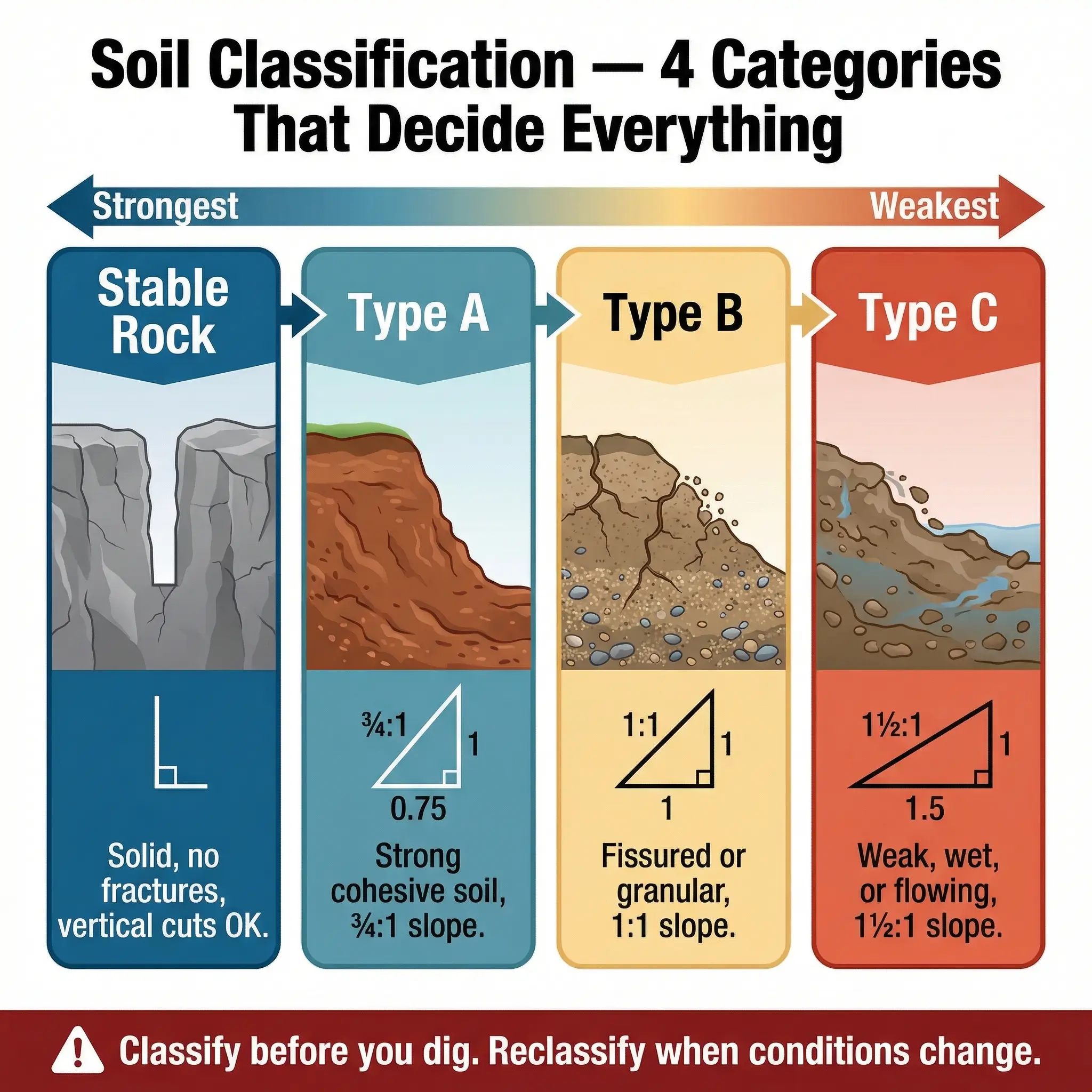
OSHA recognises four soil and rock categories, each with distinct structural properties that directly govern protection method selection:
| Classification | Description | Unconfined Compressive Strength | Examples | Maximum Allowable Slope (H:V) |
|---|---|---|---|---|
| Stable Rock | Solid mineral material with no cracks or fractures | N/A | Granite, sandstone (intact) | Vertical (90°) |
| Type A | Cohesive soil, no fissures, unconfined compressive strength ≥ 1.5 tsf | ≥ 1.5 tsf (144 kPa) | Clay, silty clay, hardpan | ¾:1 (53°) |
| Type B | Cohesive soil with fissures, or granular soil including silt and angular gravel | 0.5–1.5 tsf (48–144 kPa) | Crusite, silt, disturbed Type A, dry unstable rock | 1:1 (45°) |
| Type C | Granular soil with low cohesion, submerged soil, or soil from which water is seeping | ≤ 0.5 tsf (48 kPa) | Gravel, sand, loamy sand, submerged soil | 1½:1 (34°) |
The competent person must use at least one visual and one manual test to classify soil. Relying on visual assessment alone is a common violation I encounter repeatedly during audits. The following testing methods are the field standard for proper classification:
- Visual tests include examining soil particle size, evidence of surface cracking, layering or stratification, water seepage, spoil pile cohesion, and evidence of previously disturbed ground.
- Manual tests include the thumb penetration test (pressing a thumb into the trench wall to gauge resistance), the ribbon test (rolling soil into a thread to assess plasticity), the pocket penetrometer test (measuring unconfined compressive strength directly), and the dry strength test (breaking a dried soil clod).
- Reassessment triggers include any rainfall, change in water table, vibration from nearby equipment or traffic, temperature changes (freeze-thaw cycles), extended open time, and surcharge load changes. Classification is not a one-time event — it must be reassessed every time conditions change.
Pro Tip: I have seen soil classified as Type A on a Monday morning reclassify itself as Type C by Wednesday afternoon after overnight rain. The competent person’s job is not to classify the soil once — it is to keep classifying it until the excavation is backfilled. I make this point during every toolbox talk on excavation projects, and I carry a pocket penetrometer in my site bag as a visual reminder.
Sloping and Benching — Cutting the Ground Back to a Safe Angle
Sloping is the most intuitive excavation protection method. Instead of fighting the soil’s natural tendency to collapse, you remove enough material to create an angled wall that gravity cannot pull down. Benching is a variation where the excavation walls are cut into a series of horizontal steps rather than a continuous slope. Both methods eliminate the vertical face that makes cave-ins possible — but only if the angles are correct for the soil type.
How Sloping Works in Practice
The principle behind sloping is straightforward, but execution requires discipline. The angle of the slope must match the soil classification — not the foreman’s estimate, not what worked on the last project, and not what the excavator operator thinks looks “about right.”
The permissible slope ratios for each soil type directly determine how much additional excavation is required:
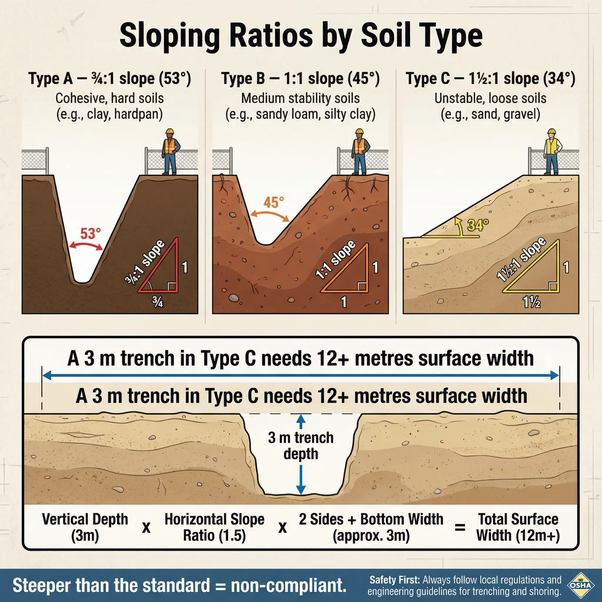
- Type A soil: ¾:1 ratio (53°). For every 1 metre of trench depth, the wall must be cut back ¾ of a metre on each side. A 3-metre deep trench in Type A soil requires 2.25 metres of additional width on each side.
- Type B soil: 1:1 ratio (45°). Equal horizontal and vertical distances. A 3-metre trench needs 3 metres of setback per side — substantially more excavation and wider site footprint.
- Type C soil: 1½:1 ratio (34°). The shallowest permissible angle. A 3-metre trench needs 4.5 metres of setback per side — a total surface opening of over 12 metres wide for a trench that is only as wide as it needs to be at the bottom.
- Stable Rock: Vertical cuts permitted. No sloping required, but the rock must genuinely be stable — no fractures, fissures, or weathering planes.
Benching as a Variation
Benching creates a staircase profile instead of a smooth slope. It is practical in cohesive soils where vertical cuts can be maintained for the height of each individual bench step, but the overall profile still must not be steeper than the maximum allowable slope for the soil type.
There are critical restrictions on where and how benching can be applied:
- Type C soil cannot be benched. The low cohesion makes vertical step faces unstable regardless of step height. Type C requires continuous sloping only.
- Maximum bench height in Type A: 1.2 metres (4 feet). Each vertical step face must not exceed this height.
- Maximum bench height in Type B: 1.2 metres (4 feet). The same restriction applies with the overall excavation profile matching the 1:1 slope requirement.
- The bottom vertical portion of a trench in any soil type must not exceed 1.2 metres for Type A benching configurations, and the overall trench profile from toe to crest must still fall within the allowable slope angle.
Advantages and Limitations of Sloping
Sloping is often the first method considered because it requires no manufactured equipment, but it carries trade-offs that are frequently underestimated during project planning:
- Advantages: No equipment procurement or installation time. No reliance on manufactured system integrity. Simple to execute with standard excavation equipment. Eliminates the vertical face entirely rather than managing it.
- Limitations: Requires significantly more excavation volume — sometimes doubling or tripling material removal. Demands a wider site footprint that may not be available in urban areas, near existing structures, or adjacent to utilities. Spoil management becomes more complex with larger volumes. Not feasible where adjacent structures, roads, or underground services limit setback distances.
Pro Tip: On a road reconstruction project in Northern Europe, we originally planned for sloped excavations across the entire alignment. Within the first week, we encountered a section where a live gas main ran parallel to the trench at just 1.8 metres from the edge. Sloping to the required angle would have undermined the gas main’s bedding. We switched to a shoring system for that segment. The lesson: always walk the full excavation alignment and identify constraints before committing to a single protection method for the entire project.
Shoring Systems — Holding the Walls in Place
Shoring is an active support system that physically resists the lateral earth pressure trying to push trench walls inward. Unlike sloping, which removes the hazard by reshaping the excavation, shoring manages the hazard by installing structural members that hold the soil in place. This makes shoring essential in situations where sloping is not feasible — narrow rights-of-way, urban streets, areas adjacent to existing foundations, and any location where excavation width must be minimised.
Types of Shoring Systems
The three primary shoring categories each serve different operational contexts. Selection depends on soil type, trench depth, available equipment, and how long the excavation will remain open.
The following systems represent the field-standard options for trench wall support:
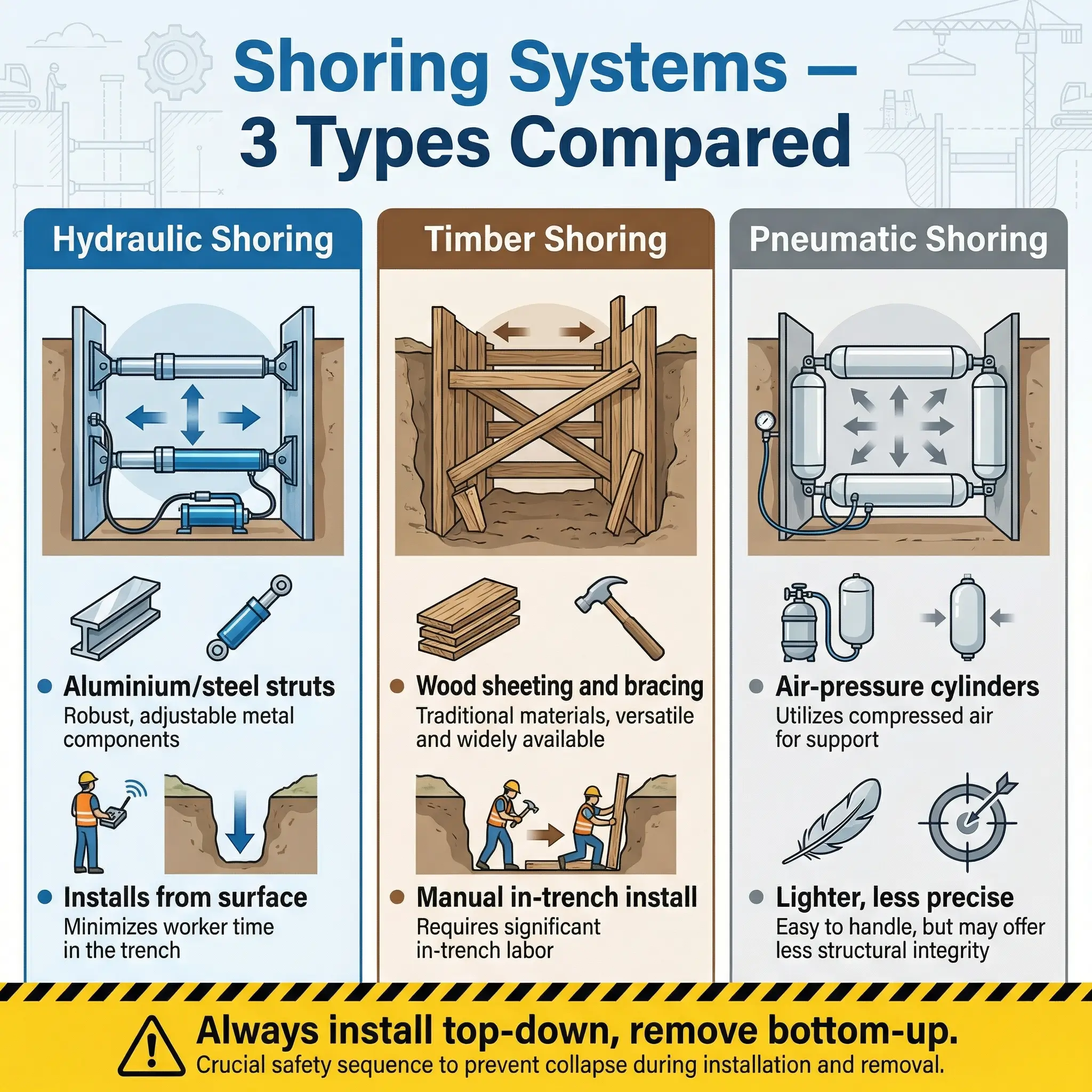
- Hydraulic shoring uses aluminium or steel hydraulic cylinders (struts) placed horizontally between the trench walls to apply outward pressure against vertical aluminium or steel rails (uprights or panels). Cylinders are preloaded using hydraulic pumps to create active pressure against the soil before the wall has a chance to move. This is the most common system on urban utility projects because it installs quickly, adjusts to varying trench widths, and can be placed and removed from the surface without workers entering the unprotected trench.
- Timber shoring uses wooden planks (sheeting) placed vertically against the trench walls, supported by horizontal wales (runners) and cross-braces (struts). Timber shoring is slower to install and requires workers to enter the trench for placement, but it remains in use on smaller projects and in regions where hydraulic systems are not readily available. OSHA provides timber shoring design tables in Appendix C of Subpart P based on soil type and trench depth.
- Pneumatic shoring operates on the same principle as hydraulic shoring but uses air pressure instead of hydraulic fluid. It is lighter and sometimes faster to deploy but offers less precise preload control. Pneumatic systems are less common on deeper excavations where higher pressures are required.
Installation Sequence — Getting It Right
Shoring installation follows a strict sequence. Violating the order exposes workers to unprotected trench walls during the most dangerous phase — when the system is partially installed and workers are in the trench.
The correct installation sequence for hydraulic shoring is critical to worker safety and system effectiveness:
- Excavate to the first lift depth (typically 1.2 m or the first strut level) while the excavation remains shallow enough that no protection is yet required, or install the first set of struts from the surface using equipment reach.
- Place the first set of hydraulic struts at the top of the excavation, with cylinders bearing firmly against vertical rails or sheeting on both walls. Preload the cylinders using the hydraulic pump to engage active pressure against the soil.
- Continue excavation to the next lift depth and install the second tier of struts before excavating further. This top-down installation ensures workers always have at least one level of support above them during deeper excavation.
- Repeat the lift-and-shore sequence until the trench reaches final depth. Strut spacing (vertical and horizontal) must comply with the manufacturer’s tabulated data or the registered professional engineer’s design for the specific soil type and depth.
- Remove shoring in reverse order (bottom-up) during backfilling. Never remove lower struts before upper struts are secured and backfill has replaced the lateral support. Workers must not be in the trench when struts are being removed unless protected by other means.
Key principle from OSHA Appendix D: Hydraulic shoring systems must be installed and used in accordance with the manufacturer’s tabulated data or, alternatively, designed by a registered professional engineer. Using a system outside its rated capacity is not a judgement call — it is a violation.
Pro Tip: The most dangerous moment in a shoring operation is the transition between lifts — when the excavator is deepening the trench and the next set of struts has not yet been installed. I have stopped jobs where operators were digging two or three lifts ahead of the shoring crew because “they’ll catch up.” They never catch up fast enough. The rule is absolute: no excavation advances ahead of installed shoring. Period.
Shielding — Protecting Workers Inside the Trench
Shielding takes a fundamentally different approach from both sloping and shoring. Instead of preventing the cave-in or holding the walls back, a shield accepts that collapse may occur and places workers inside a structure strong enough to withstand it. The most common shielding system is the trench box (also called a trench shield) — a prefabricated steel or aluminium structure placed in the trench that creates a protected workspace within which workers operate.
How Trench Boxes Work
A trench box consists of two vertical steel wall panels connected by internal steel spreaders (cross-members) that maintain a fixed distance between the panels. The box sits in the trench with the panels parallel to and close against the trench walls. If soil collapses, it strikes the outside of the shield panel rather than the workers inside. The shield does not necessarily prevent wall movement — it prevents wall movement from reaching the workers.
The operational characteristics of trench boxes make them the default choice on many pipeline and utility projects:
- Rapid deployment. Trench boxes are lowered into place by excavator and can be operational within minutes. No complex installation sequence, no in-trench assembly during initial placement.
- Mobility. On linear excavations (pipelines, sewer mains, utility corridors), the trench box can be “dragged” or “leap-frogged” along the trench as work progresses. This is significantly faster than installing and removing shoring at each work location.
- No soil classification dependency for basic use. Trench boxes are rated by the maximum depth and lateral pressure they can withstand. A shield rated for the actual depth and soil conditions can be used in any soil type, though the competent person must still verify that the shield’s rating matches or exceeds the actual loading conditions.
- Workers must stay inside the shield at all times. The protection exists only within the footprint of the shield. Workers who step outside the box to retrieve tools, check pipe grade, or access the trench end beyond the shield are completely unprotected.
Trench Box Limitations and Common Misuse
Shielding systems are highly effective when properly matched to conditions and correctly used, but I have seen repeated misapplication patterns on construction sites that turn a viable system into a false sense of security.
The following field failures represent the most common trench box misuse patterns across projects I have audited:
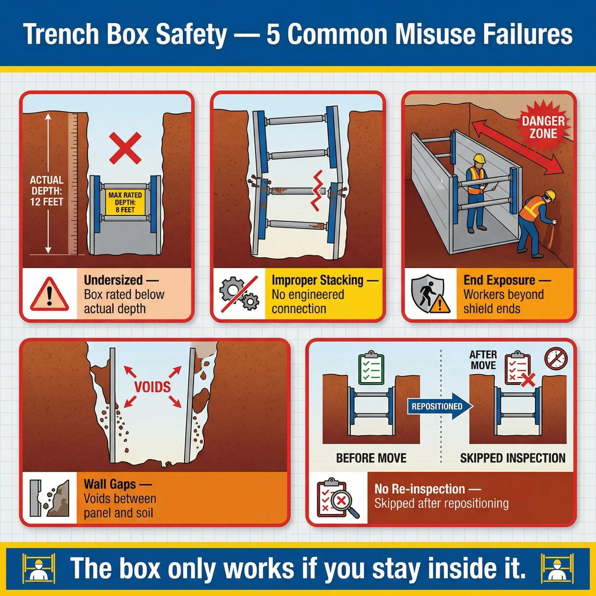
- Undersized boxes. Using a trench box rated for a shallower depth than the actual excavation. Every trench box has a manufacturer’s depth rating stamped or labelled on it. Exceeding that rating means the spreaders and panels may not withstand the actual lateral earth pressure. I have seen 2.4-metre rated boxes sitting in 3.5-metre trenches with the top of the box below grade level — offering zero protection above the box and inadequate structural capacity at depth.
- Stacking violations. Two trench boxes can be stacked vertically for deeper trenches, but only if the manufacturer’s tabulated data explicitly permits stacking for those specific units and the connection hardware is installed correctly. Placing one box on top of another without engineered stacking provisions is a structural gamble.
- End exposure. The open ends of a trench box are the most dangerous zones. Workers frequently walk past the box ends to access pipe joints or check alignment beyond the shielded area. This is an unprotected vertical face — all the risk of an unshored trench concentrated at the exact point where workers transition in and out.
- Gap between shield and trench wall. Significant voids between the outside of the shield panels and the trench walls allow soil to accelerate before striking the shield, increasing impact loads. They also allow workers to be pinned between the shield and falling material if they are near the edges. The competent person must assess whether backfilling or compaction of the void space is required.
- Failure to inspect after movement. Every time a trench box is repositioned — dragged, lifted, or leap-frogged — the competent person must reinspect the installation, spreader connections, panel alignment, and contact with the trench walls before workers re-enter.
Pro Tip: I require an exclusion zone painted on the trench floor at both open ends of every trench box on my projects — a bright orange spray line at 600 mm from each end with “NO ENTRY BEYOND THIS LINE” stencilled inside. It sounds basic. It has prevented at least three exposures I know of directly, because workers see the line and self-correct before a supervisor intervenes.
Selecting the Right Protection Method — A Field Decision Framework
Choosing between sloping, shoring, and shielding is not a textbook exercise. It is a field decision that must account for soil conditions, site constraints, project schedule, equipment availability, adjacent hazards, and cost — all weighed against the non-negotiable requirement to protect every worker in the excavation.
The following comparison consolidates the key selection factors across all three methods to support field-level decision-making:
| Factor | Sloping | Shoring | Shielding (Trench Box) |
|---|---|---|---|
| Best for | Open sites, rural areas, no adjacent structures | Urban areas, near structures, narrow ROW | Linear pipeline/utility, mobile work fronts |
| Site footprint | Large — requires wide setback | Minimal — trench width stays narrow | Minimal — trench width stays narrow |
| Soil dependency | High — slope angle changes per soil type | High — design tables vary by soil type | Moderate — rated by depth/pressure capacity |
| Installation speed | Fast (excavation only) | Moderate to slow (staged installation) | Fast (crane/excavator placement) |
| Worker entry during setup | No (sloping done by machine) | Yes (timber) / Minimal (hydraulic) | No (placed by machine) |
| Mobility along trench | N/A — slope is permanent until backfilled | Low — must install/remove at each location | High — drag or leap-frog along alignment |
| Cost | Low equipment cost, high excavation volume | Moderate to high (equipment + labour) | Moderate (rental + machine time) |
| Depth limitation | Practical limit ~6 m (deeper requires engineered design) | Per manufacturer data or PE design | Per manufacturer data, stackable with approval |
| Adjacent structure risk | May undermine foundations | Low — walls supported in place | Low — walls may still move but workers protected |
Combination Approaches
On complex excavation projects, a single method rarely covers the entire scope. The most effective protection strategies combine methods based on changing conditions along the excavation alignment.
Real-world projects frequently require method transitions at different zones:
- Sloped approaches with shored work areas: The access ramps and approach sections are sloped to safe angles, while the deep work zone (valve pit, manhole, junction) is shored where width must be minimised.
- Shielded trench with shored crossings: The main pipeline trench uses a drag box, but where the trench crosses under an existing utility or road, shoring is installed to provide continuous support at the crossing point.
- Sloped excavation with localised shielding: A broad excavation is sloped overall, but a trench box is placed at the specific location where workers are performing pipe jointing or testing at depth.
OSHA Appendix A, Section (b)(4): When a combination of protective systems is used, the competent person must ensure that the combined system provides protection at least equivalent to a single system designed for the maximum depth and soil conditions encountered.
Common Site-Level Mistakes That Lead to Fatalities
Every excavation fatality investigation I have participated in or reviewed shares a pattern: the hazard was known, the protection was available, and someone made a decision — or failed to make one — that put a worker in an unprotected trench. The failures are almost never exotic. They are routine, predictable, and preventable.
The following failures appear repeatedly in excavation fatality investigation reports and in my own field audit findings:
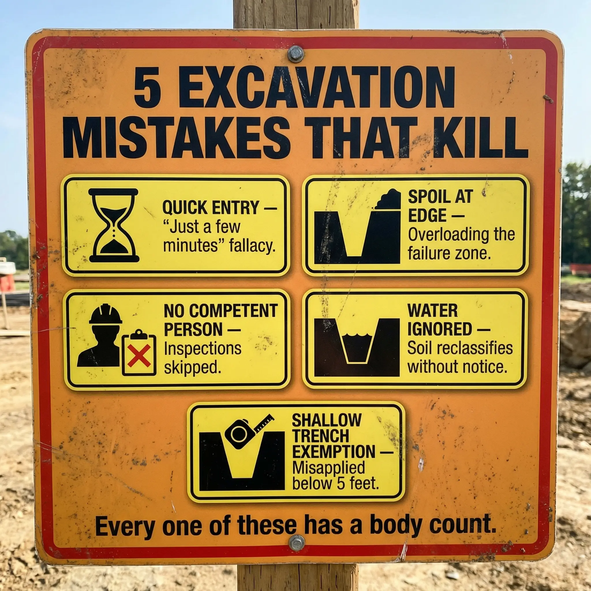
- “It’s only for a few minutes.” The single most dangerous phrase in excavation work. Cave-ins do not wait for schedules. A trench that has been open for three days can collapse in the thirty seconds a worker enters to check a pipe joint. Time in the trench does not reduce risk — it increases exposure.
- Spoil piles too close to the edge. OSHA requires spoil to be placed at least 0.6 metres (2 feet) from the edge. On congested sites, I routinely find spoil piled directly at the lip, adding surcharge load exactly where the soil face is already under maximum stress.
- No competent person on site. The competent person is not a title on a training certificate filed in the office. It is someone physically present at the excavation, conducting daily inspections before each shift and after every condition change. On too many projects, the “competent person” is a supervisor who last visited the trench two days ago.
- Ignoring water. Rainfall, groundwater infiltration, broken water mains, and even surface runoff can change soil classification within hours. Type A soil saturated with water becomes Type C soil — and the sloping angle or shoring design that was adequate yesterday is now dangerously insufficient.
- Skipping daily inspections. Conditions change overnight. Temperature fluctuations, vibration from adjacent operations, drying and cracking of cohesive soils, equipment loading near edges — all require reassessment every shift. A trench that was safe at 7 AM may not be safe at noon.
- Workers entering during box repositioning. When a trench box is being moved by excavator, there is a window where the trench is unprotected. Workers who remain in or near the trench during this operation are exposed to unshored walls and the movement hazard of the box itself.
- Failure to protect trenches less than 5 feet deep. OSHA allows a competent person to determine that protection is not needed below 5 feet only if examination indicates no potential for cave-in. This is not a blanket exemption — it is a conditional assessment. Shallow trenches in Type C soil with surcharge loads absolutely require protection.
The Competent Person — Why This Role Is Non-Negotiable
OSHA defines a competent person for excavation as someone capable of identifying existing and predictable hazards in the surroundings or working conditions that are unsanitary, hazardous, or dangerous to employees, and who has authorisation to take prompt corrective measures to eliminate them. In excavation work, this is not an administrative appointment. It is the single most important safety function on the project.
The competent person’s responsibilities on an excavation project cover the full lifecycle of every open dig:
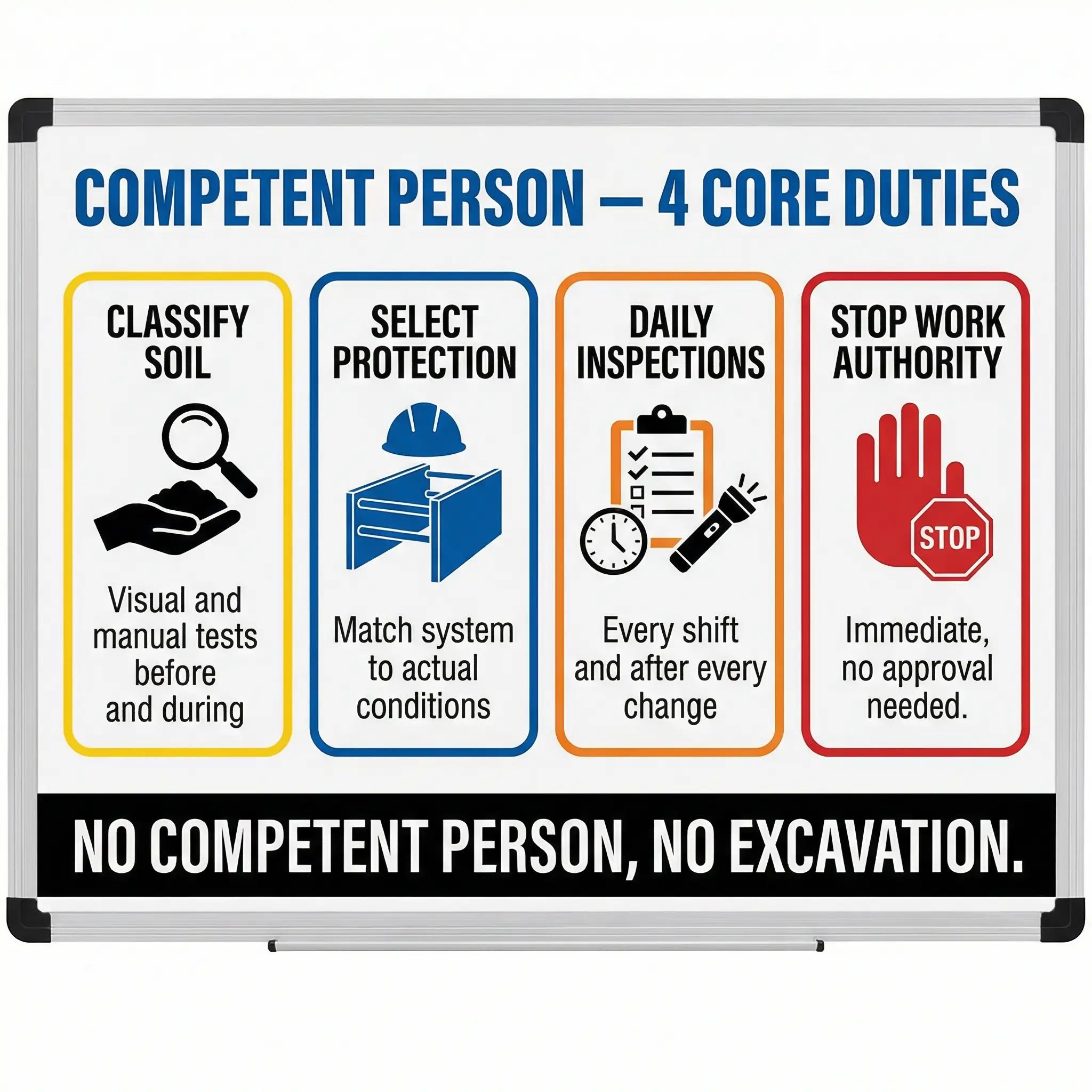
- Classify soil using visual and manual tests before excavation begins and reclassify whenever conditions change.
- Select or verify the protective system based on soil classification, trench depth, site constraints, and manufacturer’s tabulated data or engineering design.
- Conduct daily inspections of the excavation, protective systems, and adjacent areas before each shift starts and after any event that could affect stability (rain, vibration, surcharge changes, freeze-thaw).
- Authority to stop work immediately if any condition is found to be unsafe — without waiting for management approval, schedule review, or client notification. This authority must be genuine and exercised without consequence.
- Monitor for atmospheric hazards in excavations where toxic, oxygen-deficient, or flammable atmospheres could accumulate — particularly in excavations near landfills, fuel storage, sewer systems, or in soil contaminated with volatile organic compounds.
- Ensure access/egress compliance: Ladders, stairways, or ramps must be provided so that no worker in a trench over 1.2 metres deep has to travel more than 7.6 metres (25 feet) laterally to reach a means of exit.
Pro Tip: During an audit on a large infrastructure project in the Gulf, I asked the designated competent person to show me his pocket penetrometer and demonstrate a soil classification on the active trench wall. He did not have a penetrometer. He had never performed a manual test. His “classification” was based on what the geotechnical report said about the general area — not the actual soil exposed in the trench that morning. I shut the excavation down until a genuinely qualified competent person was assigned and physically demonstrated field soil testing. Paper qualifications without field capability are not competence — they are liability dressed in a certificate.
Emergency Preparedness and Rescue Planning
No excavation protection system eliminates risk entirely. Even with the correct method properly installed, the possibility of a partial collapse, mechanical failure of shoring components, or secondary hazard exposure means rescue planning is a mandatory component — not an afterthought.
Effective excavation rescue planning addresses the realities of trench emergencies before they occur:
- Pre-positioned rescue equipment. Retrieval systems, rope rescue kits, or mechanical lifting equipment must be staged at the excavation site — not in a storage container three hundred metres away. If rescue takes longer than four minutes to initiate, survival odds for a buried worker drop dramatically.
- Trained rescue personnel. Trench rescue is a specialised discipline. Well-intentioned co-workers jumping into a collapsed trench to dig with their hands are statistically more likely to become additional casualties than to successfully rescue the buried worker. Rescue teams must be trained in trench rescue shoring, secondary collapse prevention, and patient extrication techniques.
- Emergency services notification. Local fire and rescue services should be notified before excavation begins on projects involving deep trenches, confined space conditions, or remote locations. Knowing the excavation depth, soil type, and site access routes in advance saves critical response time.
- Communication plan. Every worker in and around the excavation must know the emergency signal, the assembly point, the rescue team contact, and the hospital route. This is not a poster on the site office wall — it is a verbal brief at every shift start.
Critical field reality: The first instinct of every worker who sees a colleague buried is to jump in and start digging. This instinct has killed more would-be rescuers than it has saved victims. Rescue must be controlled, systematic, and executed by trained personnel using shoring and stabilisation techniques that prevent the secondary collapse which buries the rescuers alongside the victim.
Conclusion
Excavation protection is not a compliance exercise. It is a direct, measurable barrier between a worker and a death that takes less than a minute to unfold. Sloping removes the hazard by reshaping the earth. Shoring manages it by holding the earth in place. Shielding accepts it by placing an armoured barrier between the soil and the worker. Each method has its strengths, its limitations, and its non-negotiable installation and inspection requirements. None of them work if the competent person is absent, the soil is misclassified, or the crew is pressured to skip steps because the schedule is tight.
Every excavation fatality I have investigated could have been prevented with methods that already existed, equipment that was already available, and knowledge that was already documented. The gap is never in the engineering. It is in the decision-making — the moment someone decides that production matters more than protection, or that a trench “looks fine” without testing, or that five minutes of exposure is an acceptable risk. Those decisions are where people die.
If you are responsible for an excavation — any excavation, at any depth, in any soil — your job is to ensure that no worker enters an unprotected trench under any circumstances. The protective system must be selected by a competent person, installed correctly, inspected daily, and maintained until the last shovel of backfill goes in. That is not a regulatory requirement. That is a moral obligation to the people standing at the bottom of the hole trusting that someone above them made the right call.