
TL;DR — Benching in Excavation
- Benching is a stepped excavation protective system that creates a series of horizontal steps (benches) and vertical faces in the excavation walls to prevent cave-in by reducing the effective height of each exposed soil face.
- It is only permitted in Type A and Type B soils — OSHA strictly prohibits benching in Type C soil because the material lacks the cohesive strength to hold a vertical face at any height.
- Design dimensions are not optional or field-estimated — maximum bench height, bench width, and overall slope angle are prescribed by OSHA 29 CFR 1926 Subpart P based on soil classification, and deviation kills.
- Soil classification must be performed by a competent person using at least one visual and one manual test before any benching decision is made — guessing soil type is the single most common fatal shortcut in excavation work.
- Benching fails when fundamentals are skipped — water intrusion, surcharge loads placed too close to the edge, mixed soil layers ignored, and daily inspections not conducted are the recurring factors in every benching collapse I have investigated.
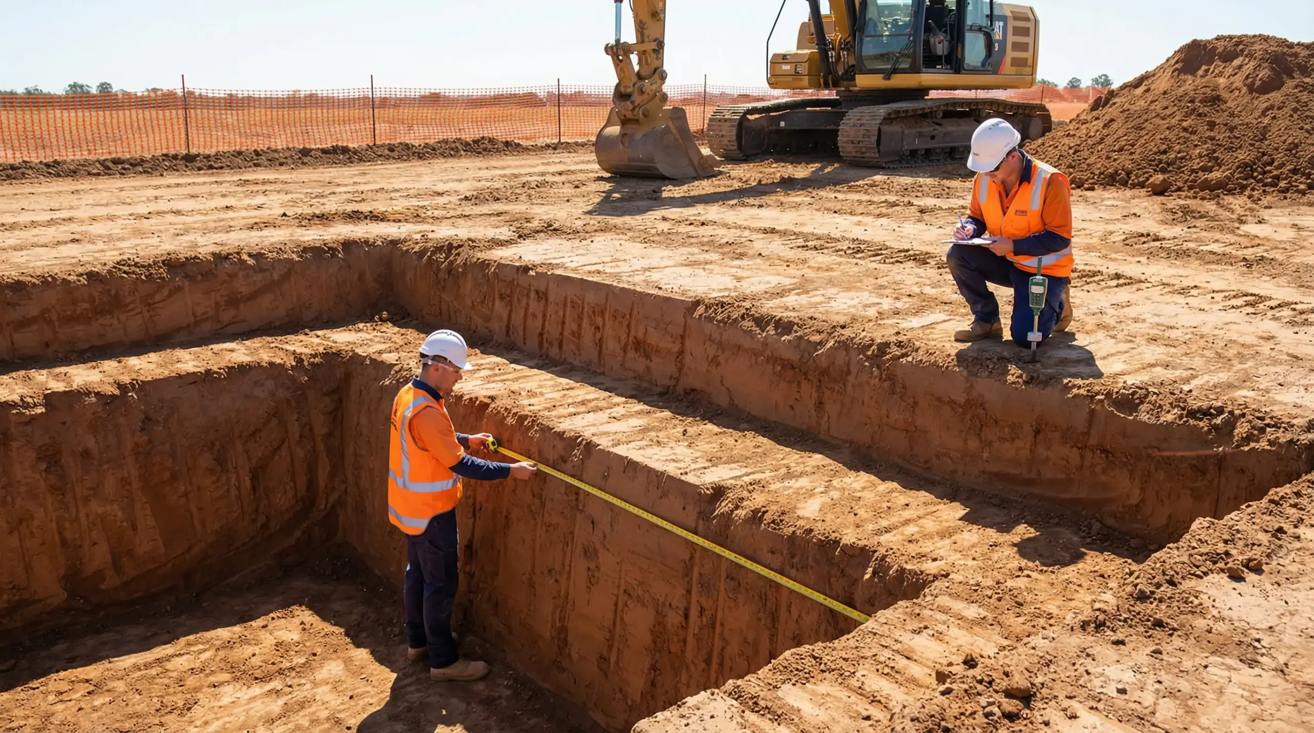
I was called to a residential development site after a 1.8-metre deep utility trench collapsed on a worker’s lower body during a sewer line installation. The contractor had dug a straight-walled trench in what he called “good clay soil” and assumed no protective system was needed because the excavation was “not that deep.” When I examined the exposed face, I could see two distinct soil layers — a thin cap of cohesive clay sitting on top of loose, granular fill from a previous backfill operation decades earlier. The granular layer had no capacity to hold a vertical face. The crew had no soil classification records, no competent person designation on file, and no protective system in place. A properly designed benching system — one that accounted for the weakest soil layer — would have prevented that collapse entirely.
Benching is one of the four recognized protective systems for excavation work under OSHA regulations, alongside sloping, shoring, and shielding. It is widely used across construction and infrastructure projects because it requires no additional equipment — just correct geometry cut into the excavation walls. But that apparent simplicity is deceptive. Benching demands accurate soil classification, strict adherence to prescribed dimensions, and ongoing monitoring of conditions that can change the soil’s behaviour overnight. This article covers what benching actually is, how it works as a protective system, the specific design requirements mandated by OSHA, the soil conditions that permit or prohibit it, and the field-level mistakes that turn a properly benched excavation into a death trap.
What Is Benching in Excavation?
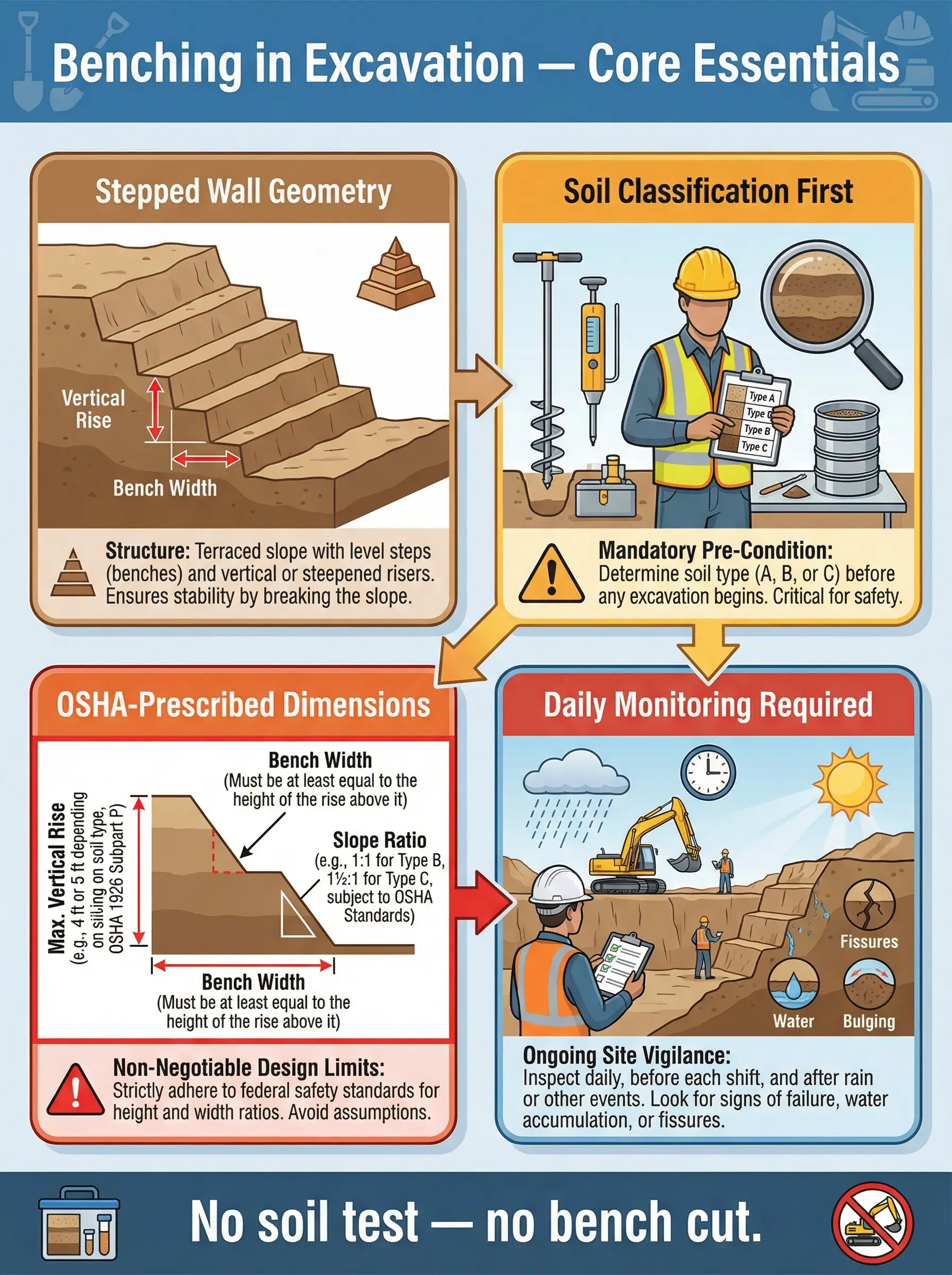
Benching is a method of protecting workers from cave-in during excavation by cutting the sides of the excavation into a series of horizontal steps — called benches — rather than leaving the walls as continuous vertical or near-vertical faces. Each bench consists of a horizontal surface (the step) and a vertical face (the riser) above or below it. The effect is a staircase-like profile that reduces the unsupported height of any single vertical section of the excavation wall.
The core engineering principle behind benching is straightforward. A tall vertical face of soil is inherently unstable because gravity and the soil’s own weight create shear forces that eventually exceed the soil’s internal cohesive strength — and the face collapses. By breaking that tall face into shorter vertical segments separated by horizontal steps, benching reduces the shear stress on each individual face segment. Each bench effectively acts as a buttress for the face above it, redistributing load and reducing the volume of material that could fail at any single point.
OSHA defines benching under 29 CFR 1926.650 as a method of protecting employees from cave-ins by excavating the sides of an excavation to form one or a series of horizontal levels or steps, usually with vertical or near-vertical surfaces between levels. There are two recognised configurations:
The distinction between the two types matters for design and application, and misunderstanding it is a common site-level error that I have encountered on multiple projects across different regions.
- Simple benching uses a single series of uniform steps cut into the excavation wall, where each bench has the same height and width, and the overall profile from top to bottom follows a consistent stepped angle. This is the more common configuration on straightforward utility and foundation excavations.
- Multiple benching uses a series of benches where the vertical face height or step width varies at different levels of the excavation. This configuration is used in deeper excavations or where soil conditions change with depth, requiring adjusted geometry at different horizons.
OSHA 29 CFR 1926.652(b)(1): Excavations shall be sloped, benched, shored, or shielded by a system designed in accordance with the requirements of this section. The design must be based on actual soil classification — not assumption.
Pro Tip: On every excavation project I manage, I require the competent person to physically mark the intended bench cut lines on the ground surface with spray paint before any digging begins. This forces the operator to follow a planned geometry instead of free-cutting the wall by eye. The ten minutes spent marking saves hours of rework — and potentially saves a life.
Why Benching Is Used as a Protective System
Contractors and project teams gravitate toward benching for practical reasons rooted in cost, equipment availability, and site constraints. Understanding why benching is selected — and when it should not be — is essential for any construction HSE professional reviewing excavation plans.
- No additional equipment required: Unlike shoring (which requires hydraulic struts, soldier piles, or timber bracing) and shielding (which requires trench boxes or steel plates), benching is achieved purely through excavation geometry. The excavator that digs the trench also cuts the benches. This eliminates equipment rental costs, delivery logistics, and the time needed to install and remove protective hardware.
- Faster installation in suitable soils: In competent Type A soil, a skilled excavator operator can cut clean benches as part of the normal digging sequence without stopping to install hardware. On short-duration utility installations — water mains, sewer connections, electrical duct banks — this speed advantage is significant.
- Works well for wide excavations: Shielding with trench boxes is practical in narrow trenches but becomes impractical in wide excavations such as building foundations, retention basins, or large-diameter manhole installations. Benching accommodates wide excavation footprints without custom-fabricated shields.
- Suitable for staged or long-duration excavations: On projects where the excavation remains open for days or weeks — such as basement construction or large drainage installations — benching provides continuous passive protection without the need to reposition shields as work progresses along the trench.
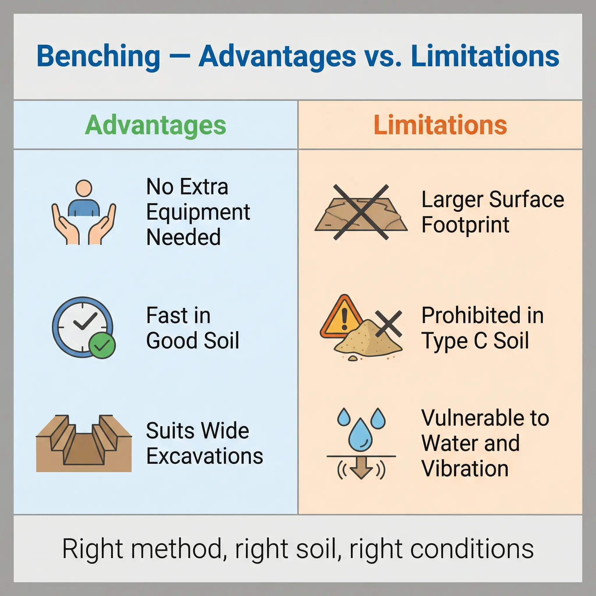
Despite these advantages, benching is not a universal solution and carries specific limitations that field teams frequently underestimate.
- Requires more surface area: Every bench step consumes horizontal space. A benched excavation has a significantly larger surface footprint than a vertically shored or shielded excavation of the same depth. On congested sites with adjacent structures, utilities, or property boundaries, the required footprint may not be available.
- Prohibited in Type C soil: This is a non-negotiable OSHA restriction. Type C soils — granular, non-cohesive, submerged, or previously disturbed materials — cannot hold even a short vertical face reliably. Benching in Type C soil is not just non-compliant; it is a collapse waiting to happen.
- Vulnerable to changing conditions: Water infiltration, vibration from adjacent traffic or equipment, freeze-thaw cycles, and surcharge loads from stockpiled material or parked equipment can degrade a bench that was stable when first cut. Benching requires continuous monitoring in a way that shoring and shielding — being engineered structural systems — do not.
Pro Tip: Whenever I review an excavation plan that specifies benching as the protective system, my first question is not about the bench dimensions — it is about the spoil pile location. If the excavated material is stockpiled within two feet of the excavation edge, the surcharge load can destabilise even a perfectly cut bench. OSHA requires spoil piles to be set back at least two feet from the edge, but on congested sites, I push for a setback equal to the excavation depth whenever possible.
Soil Classification — The Non-Negotiable First Step
Every benching decision begins — and must begin — with soil classification. This is not a formality or a documentation exercise. It is the engineering foundation on which every bench dimension is based. I have reviewed excavation collapse investigations across three continents, and in every case where benching failed, the root cause chain traced back to one of two soil classification failures: no classification was performed at all, or the classification was done incorrectly and the soil was assigned a higher category than its actual properties justified.
OSHA 29 CFR 1926 Subpart P, Appendix A establishes the classification system and requires that soil and rock be classified by a competent person as one of four categories. The classification determines which protective systems are permitted and what dimensions apply.
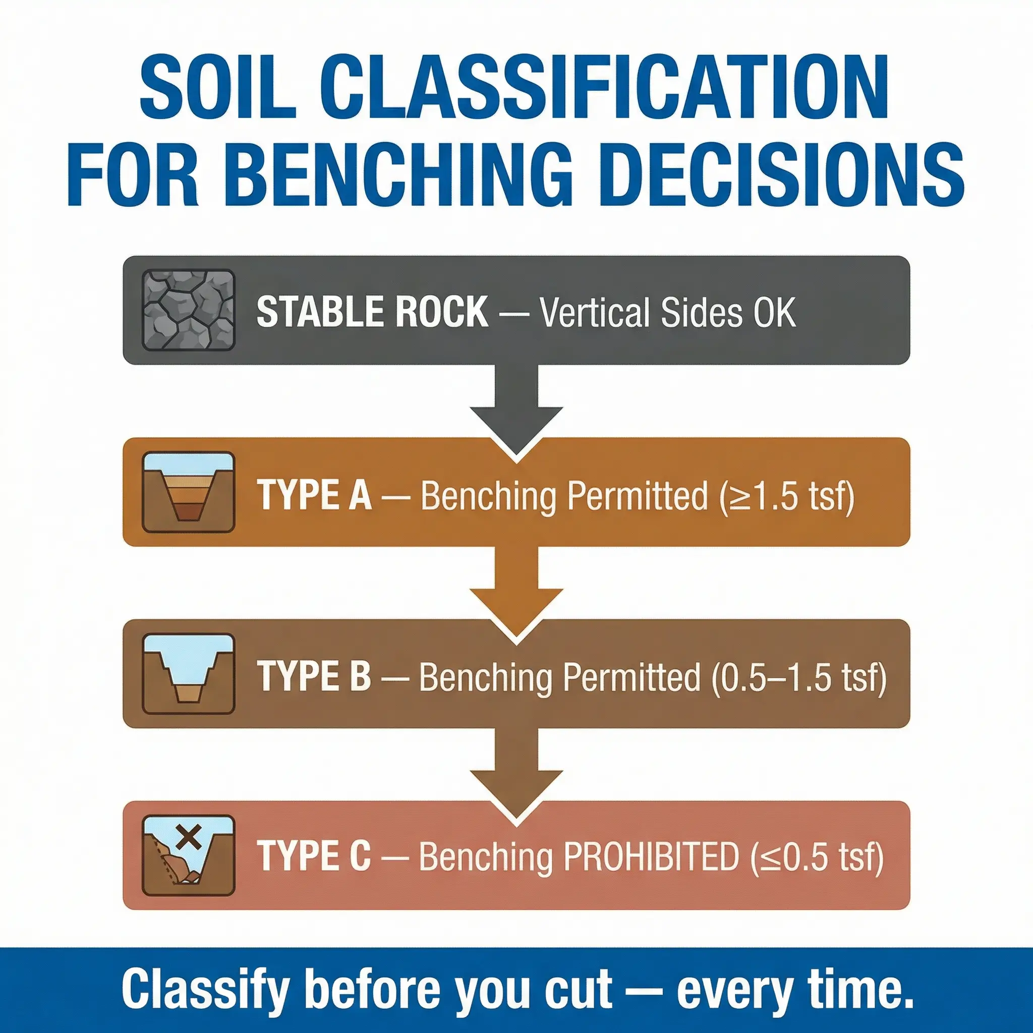
- Stable Rock: Naturally occurring solid mineral matter that can be excavated with vertical sides and remain intact. No protective system is required. Rarely encountered in typical construction excavations and must not be assumed — even rock formations can contain fracture planes, weathered zones, or clay seams that compromise stability.
- Type A Soil: Cohesive soils with an unconfined compressive strength of 1.5 tons per square foot (tsf) or greater. Examples include clay, silty clay, sandy clay, and clay loam. Type A is the strongest soil classification and permits the least aggressive bench geometry. However, OSHA excludes soil from Type A if it is fissured, subject to vibration, previously disturbed, or part of a sloped, layered system where the layers dip into the excavation.
- Type B Soil: Cohesive soils with an unconfined compressive strength between 0.5 and 1.5 tsf, plus granular cohesionless soils including angular gravel, crushed rock, silt, silt loam, and sandy loam. Type B also includes previously disturbed soils that would otherwise classify as Type A, and soils that are fissured or subject to vibration. Benching in Type B requires steeper bench angles and shorter vertical face heights than Type A.
- Type C Soil: Cohesive soils with an unconfined compressive strength of 0.5 tsf or less, plus granular soils including gravel, sand, loamy sand, submerged soil, soil from which water is freely seeping, and submerged rock that is not stable. Benching is not permitted in Type C soil under any configuration.
How Soil Classification Must Be Performed
The competent person must use at least one visual test and at least one manual test to classify the soil. Relying on visual appearance alone — which is the most common shortcut I encounter on site — is explicitly insufficient under OSHA requirements.
- Visual tests involve examining the excavated material and the excavation face for particle size, moisture content, evidence of water seepage, layering, fissures or cracks, previous disturbance indicators (like backfill material, utility bedding, or construction debris), and the behaviour of the soil as it is excavated (does it come out in clumps or fall apart?).
- Manual tests involve physically testing the soil to estimate its unconfined compressive strength and cohesive properties. Common field manual tests include the thumb penetration test (pressing a thumb into a freshly exposed soil clod — if the thumb penetrates with difficulty, it suggests Type A; if easily, Type B or C), the ribbon test (rolling soil into a ribbon to assess plasticity and cohesion), the pocket penetrometer test (using a spring-loaded device to measure compressive strength directly), and the dry strength test (breaking a dried soil clod to assess cohesion).
The classification must be documented and must be repeated whenever conditions change — after rainfall, when a new soil layer is exposed at greater depth, when vibration sources change, or when water conditions shift.
| Soil Type | Unconfined Compressive Strength | Benching Permitted? | Maximum Vertical Face Height (Simple Bench) | Overall Slope Angle |
|---|---|---|---|---|
| Stable Rock | N/A — solid mineral matter | Not needed — vertical sides permitted | N/A | 90° |
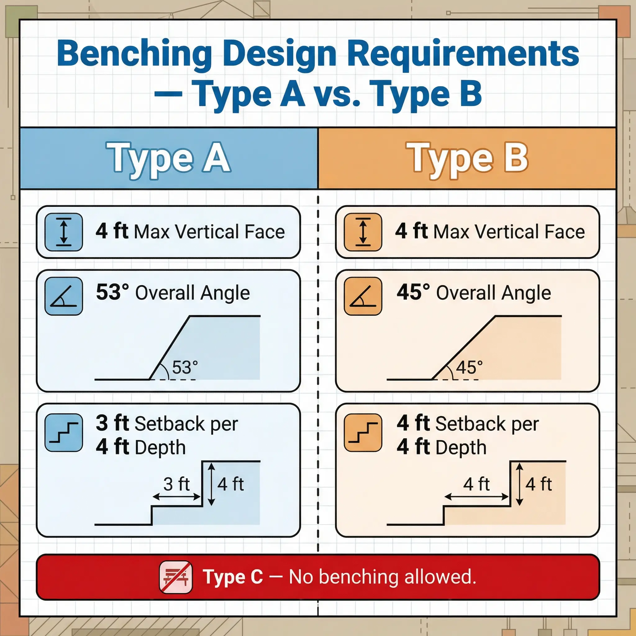
| Type A | ≥ 1.5 tsf | Yes | 4 feet (1.2 m) | 53° (¾H:1V) |
| Type B | 0.5–1.5 tsf | Yes | 4 feet (1.2 m) | 45° (1H:1V) |
| Type C | ≤ 0.5 tsf | No — prohibited | N/A | 34° (1½H:1V) — sloping only |
Critical field rule: When an excavation passes through multiple soil layers, the entire excavation must be classified and protected based on the weakest layer present. If you have Type A clay from the surface to 1.5 metres, then Type C sand below that, the entire excavation is treated as Type C — and benching is not permitted at any level. This layered soil rule is the one I see violated most frequently, and it has been the direct cause of fatalities.
Pro Tip: I carry a pocket penetrometer on every excavation site visit. It costs under $50, fits in a coverall pocket, and gives you a quantitative unconfined compressive strength reading in seconds. When a contractor tells me the soil is “Type A — it’s good clay,” I hand them the penetrometer and ask them to prove it. The number does not lie, and it ends arguments before they start.
OSHA Design Requirements for Benching
The design dimensions for benching are not suggestions, guidelines, or starting points for engineering judgment. They are prescribed minimums set by OSHA based on soil mechanics research and failure mode analysis. Field teams that treat these dimensions as approximate — “close enough” — are operating outside compliance and outside the margin of safety that prevents collapse.
OSHA provides two paths for designing a benching system under 29 CFR 1926.652(b). Understanding which path applies — and which one the contractor is actually using — is a critical review point for any HSE professional approving an excavation plan.
Option 1 — OSHA Appendix B Configurations (Most Common)
Appendix B of Subpart P provides pre-engineered slope and bench configurations that can be used without additional engineering calculations, provided the soil has been correctly classified and the excavation does not exceed 20 feet in depth. These are the configurations used on the vast majority of construction excavation projects.
The following dimensions and angles are the core design parameters that every competent person and every HSE professional must know without looking them up, because they govern go/no-go decisions in the field every day.
- Type A Soil — Simple Benching: The maximum allowable height of the first vertical face (the lowest bench riser) is 4 feet. Each subsequent bench step must maintain the overall excavation profile within an angle of 53 degrees from horizontal (equivalent to a ¾ horizontal to 1 vertical ratio). In practical terms, for every 4 feet of vertical depth, the bench must step back 3 feet horizontally.
- Type A Soil — Multiple Benching: Permitted with a maximum vertical face height of 4 feet at each level. The overall angle from the toe of the lowest bench to the top of the excavation must not exceed 53 degrees from horizontal. Multiple benching in Type A allows more flexibility in step width distribution but the cumulative geometry must still fall within the 53-degree envelope.
- Type B Soil — Simple Benching: The maximum allowable height of each vertical bench face is 4 feet. The overall excavation profile must be within an angle of 45 degrees from horizontal (1 horizontal to 1 vertical ratio). This means for every 4 feet of vertical depth, the bench must step back 4 feet horizontally — consuming more surface area than Type A benching for the same depth.
- Type B Soil — Multiple Benching: Not specifically addressed in Appendix B as a standard configuration. Where multiple benching is needed in Type B soil, the excavation generally requires a registered professional engineer’s design under Option 2.
- Type C Soil: No benching configuration is permitted. The only allowed excavation profile in Type C soil under Appendix B is sloping at 34 degrees from horizontal (1½ horizontal to 1 vertical). Shoring or shielding are the alternative protective systems.
| Parameter | Type A Simple | Type A Multiple | Type B Simple |
|---|---|---|---|
| Max vertical face height | 4 ft (1.2 m) | 4 ft (1.2 m) per level | 4 ft (1.2 m) |
| Overall slope angle | 53° (¾H:1V) | 53° (¾H:1V) | 45° (1H:1V) |
| Horizontal setback per 4 ft depth | 3 ft (0.9 m) | Varies by level (within 53° envelope) | 4 ft (1.2 m) |
| Maximum depth without PE design | 20 ft (6.1 m) | 20 ft (6.1 m) | 20 ft (6.1 m) |
| Type C permitted? | N/A | N/A | N/A — No benching in Type C |
Option 2 — Registered Professional Engineer Design
When the excavation exceeds 20 feet in depth, when soil conditions are complex or layered, when the standard Appendix B configurations cannot be achieved due to site constraints, or when the contractor wants to use a configuration not covered by Appendix B, a registered professional engineer (PE) must design the benching system. The PE design must be in writing, must bear the engineer’s seal, and must be based on actual site conditions — not generic soil assumptions.
In my experience, Option 2 is significantly underused. Contractors will stretch Appendix B configurations to fit situations they were never designed for — layered soils, water-bearing strata, adjacent foundation loads — rather than engage a geotechnical engineer. The engineering cost for a PE-designed benching plan on a complex excavation is typically $2,000–$5,000. The cost of a collapse — in human terms, project delay, regulatory penalties, and litigation — is incomparably higher.
OSHA 29 CFR 1926.652(b)(1): Option 1 configurations (Appendix B) are permitted for excavations 20 feet or less in depth. Excavations greater than 20 feet must be designed by a registered professional engineer.
Step-by-Step Benching Implementation in the Field
Knowing the design requirements on paper is one thing. Translating them into a correctly executed bench cut in actual soil — with a real excavator operator, real time pressure, and real site constraints — is where the gap between compliance and safety either closes or widens fatally. The following sequence reflects the process I use and enforce on every excavation project where benching is the selected protective system.
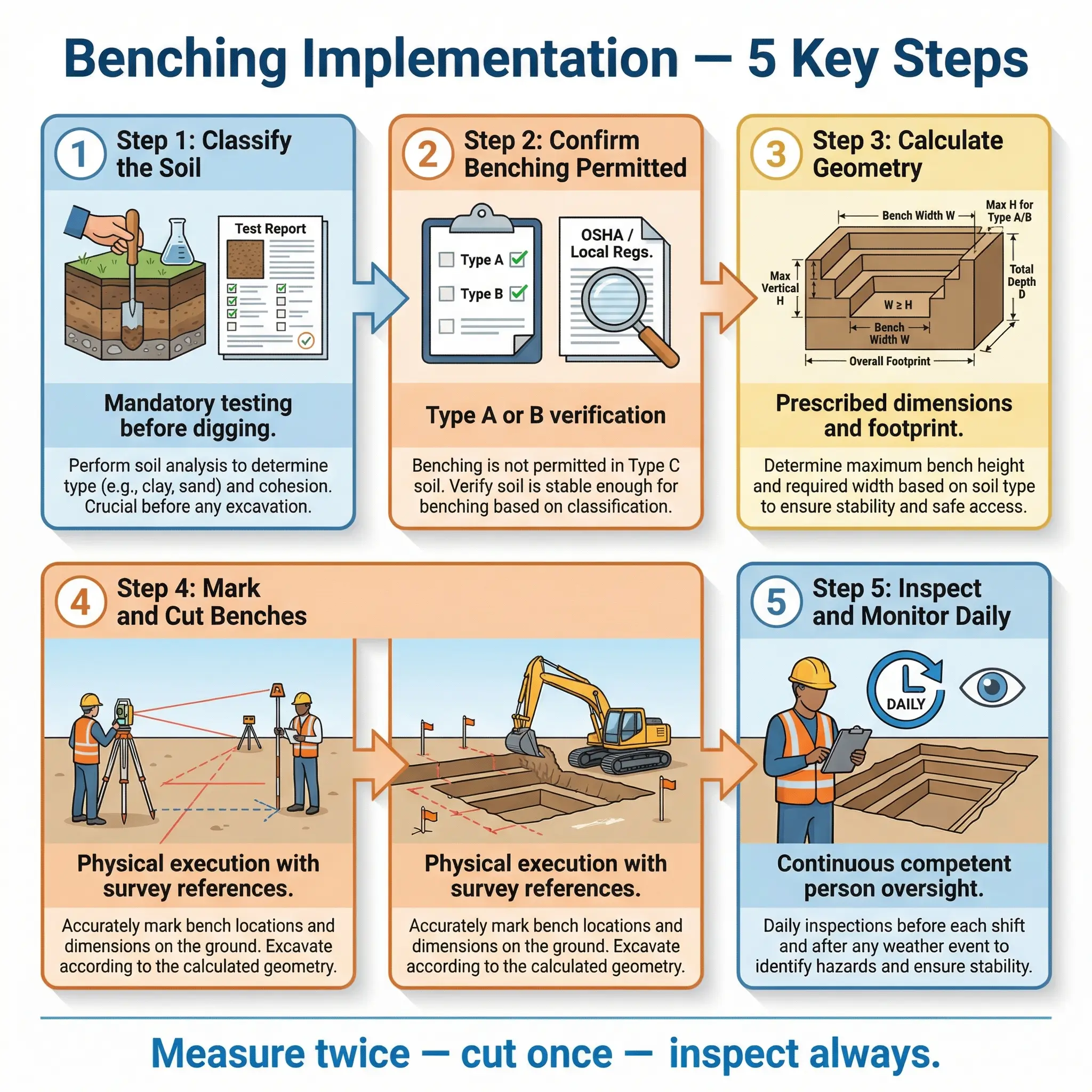
- Step 1 — Classify the soil: The competent person performs visual and manual tests on the in-situ soil and any stockpiled material. Classification is documented on the excavation permit or inspection form before any digging begins. If multiple soil layers are visible or expected based on geotechnical data, the weakest layer governs the design.
- Step 2 — Verify benching is permitted: Confirm that the classified soil type allows benching (Type A or Type B only). Confirm the excavation depth is within the 20-foot Appendix B limit. If either condition fails, select an alternative protective system or engage a PE.
- Step 3 — Calculate required bench geometry: Based on soil classification, determine maximum vertical face height (4 feet), overall slope angle (53° for Type A, 45° for Type B), and total horizontal setback required for the planned excavation depth. Calculate the total surface footprint and confirm it fits within the available site area, accounting for spoil pile setback and equipment working room.
- Step 4 — Mark bench cut lines on the ground: Using survey paint, stakes, or string lines, mark the top edge of each bench step on the ground surface before digging starts. This gives the excavator operator a physical reference and eliminates guesswork. On deeper excavations with multiple bench levels, mark each level’s setback line.
- Step 5 — Execute the bench cuts: The excavator operator cuts each bench step to the marked dimensions, starting from the top level and working down. The competent person verifies each bench face height and step width with a tape measure or laser level as each level is completed — not after the entire excavation is dug.
- Step 6 — Inspect and verify continuously: After initial bench cuts are complete, the competent person inspects the excavation before any worker entry and at least daily thereafter. Inspection includes checking for tension cracks on bench surfaces, signs of water seepage or saturation, undercutting at the base of vertical faces, surcharge loads within the setback zone, and changes in soil conditions at newly exposed layers.
- Step 7 — Respond to changing conditions: If inspection reveals deterioration — cracking, sloughing, water intrusion, soil type change — work is stopped, the excavation is evacuated, and the competent person reassesses. The benching geometry may need to be widened, the excavation may need to be re-classified, or a different protective system may need to be implemented.
Pro Tip: I train excavator operators to cut the first bench 6 inches wider than the minimum required setback. That small margin absorbs minor sloughing and crumbling at the bench edge without immediately putting the geometry out of compliance. It is cheaper to dig 6 inches more soil than to rework a collapsed bench — or explain a cave-in to a regulator.
Common Field Failures and Mistakes in Benching
Every benching collapse I have investigated — and I have investigated more than I would like to remember — shared the same handful of root causes. These are not obscure engineering failures. They are basic, preventable site-level mistakes that persist because of time pressure, cost pressure, and the dangerous normalisation of non-compliance on excavation projects.
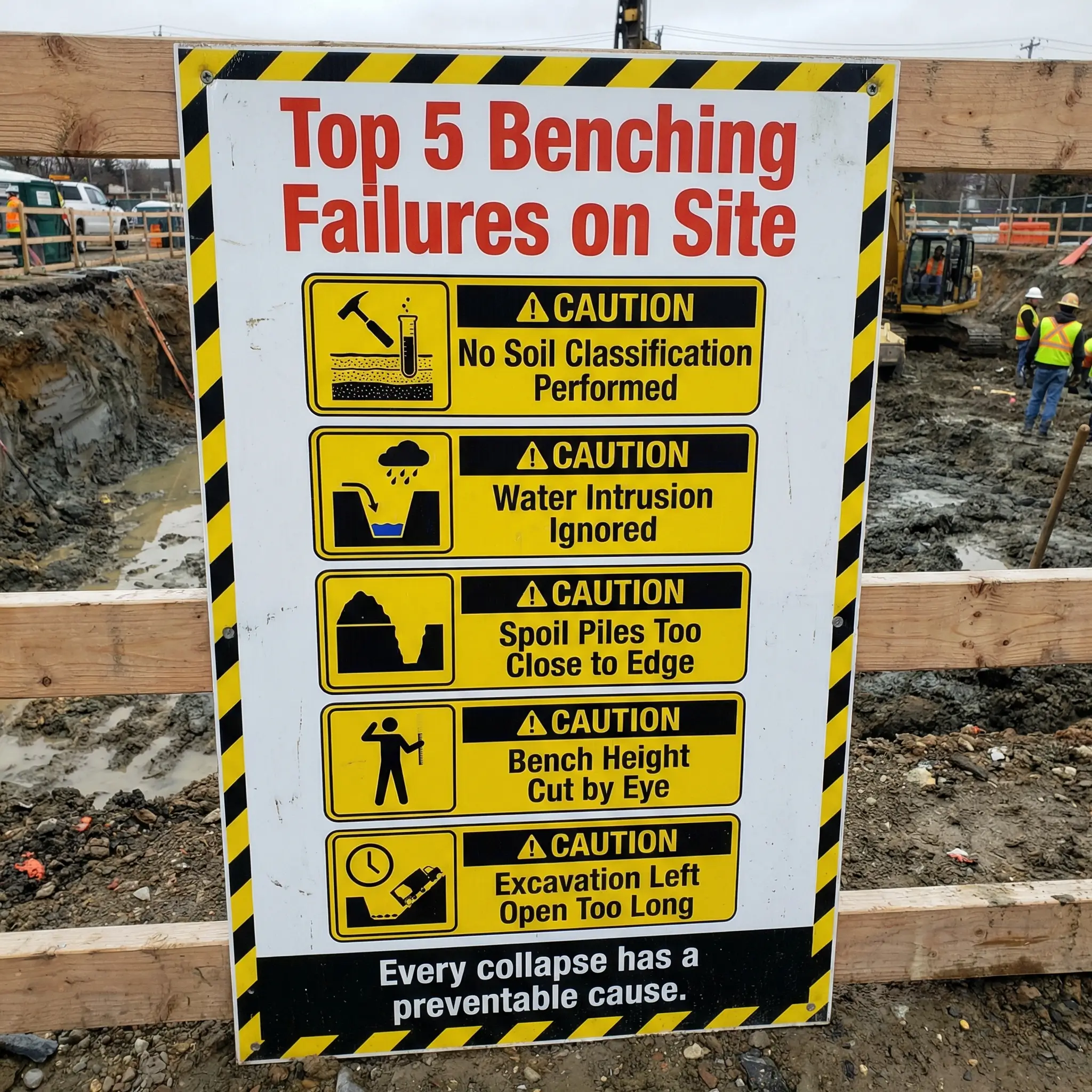
Failure to Classify Soil or Misclassifying Soil Type
This is the single most frequent and most dangerous failure. Contractors who have dug in the same area before assume the soil is “the same as last time.” Competent persons who are competent in name only perform a quick visual glance and declare the soil Type A without a manual test. Previously disturbed soil — from backfilled utility trenches, old foundations, or graded fill — gets classified as if it were undisturbed native material, when OSHA explicitly downgrades previously disturbed soil from Type A.
- The field reality: On a pipeline project in the Middle East, a crew was benching a 3-metre deep trench through what the site supervisor called “hard clay — Type A, no question.” A pocket penetrometer test showed 0.8 tsf — firmly Type B. The benching geometry they were using was designed for Type A. The difference between a Type A and Type B bench angle at that depth meant the bench face was oversteepened by nearly a metre of horizontal setback. The trench was shut down and re-cut before anyone entered it.
Ignoring Water and Changing Conditions
Water transforms soil behaviour faster than any other single factor. A bench cut in dry Type A clay on Monday can become an unstable Type C failure surface by Wednesday after 48 hours of rain. Groundwater seepage at the base of a bench face creates hydrostatic pressure behind the vertical face and lubricates the shear plane along which the bench will fail.
- Seepage at the bench face is a visible, unmistakable warning sign that most field crews either do not recognise or choose to ignore because addressing it means stopping work.
- Ponding on bench surfaces adds surcharge load to the step and saturates the soil directly above the next vertical face — weakening the precise area that needs to be strongest.
- Freeze-thaw cycles in cold climates cause the bench face to expand and contract, opening tension cracks that propagate behind the face and create block-failure potential.
Surcharge Loads Too Close to the Edge
OSHA requires spoil piles and equipment to be set back at least 2 feet from the excavation edge. On real sites — especially congested urban utility projects — this setback is treated as optional. I have seen excavated material piled directly against the bench face, dump trucks parked with their rear wheels within inches of the top bench step, and concrete pipes staged on the bench surface itself.
Every kilogram of material placed on or near a bench adds to the forces driving the bench face toward failure. The soil does not know whether the weight above it is native ground or a stockpile — it responds to load.
Cutting Benches by Eye Without Measurement
When the excavation plan says “4-foot maximum vertical face” and no one on site has a tape measure or laser level, the bench face height becomes a guess. Excavator operators — even skilled ones — routinely underestimate vertical heights when looking down into a trench from the cab. A face that looks like 4 feet from above can be 5 or 6 feet when measured from the trench floor. That extra foot or two of unsupported vertical face can be the difference between a stable bench and a fatal collapse.
- Field fix: Mark the 4-foot height on the excavator bucket or on a visible ranging pole placed in the trench. Give the operator a physical reference — not a memory of what 4 feet looks like.
Leaving Excavations Open Longer Than Planned
Benching design assumes a certain exposure period. An excavation that was planned to be open for one day but remains open for a week due to schedule delays, weather interruptions, or inspection hold-ups is exposed to cumulative degradation — drying and cracking, wetting and softening, traffic vibration, and thermal cycling — that was never accounted for in the original bench geometry.
| Common Failure | Root Cause | Consequence |
|---|---|---|
| No soil classification | Time pressure, untrained personnel | Bench designed for wrong soil — collapse risk |
| Water intrusion ignored | No daily inspection, rain not treated as trigger | Bench face saturation — shear failure |
| Spoil pile on bench edge | Site congestion, no enforced setback | Surcharge-induced collapse |
| Bench face height exceeded | No field measurement, operator guesswork | Overstressed vertical face — block failure |
| Extended open duration | Schedule delays, no re-assessment protocol | Cumulative degradation — progressive failure |
The Competent Person Requirement — Who Decides, Who Inspects
OSHA places the entire weight of excavation safety on a single defined role: the competent person. Under 29 CFR 1926.650, a competent person is someone capable of identifying existing and predictable hazards in the surroundings or working conditions that are unsanitary, hazardous, or dangerous to employees, and who has authorisation to take prompt corrective measures to eliminate them. In excavation work, the competent person is not an advisory role — it is an enforcement role with stop-work authority.
The competent person’s responsibilities in a benched excavation are specific, documented, and directly tied to preventing collapse.
- Perform and document soil classification using at least one visual and one manual test before any worker enters the excavation. The classification must be recorded and available on site.
- Select the protective system — benching, sloping, shoring, or shielding — based on the classified soil type, excavation depth, site conditions, and project requirements. The competent person must be able to explain why benching was selected and why the chosen configuration is appropriate.
- Verify bench dimensions against the applicable OSHA Appendix B configuration or PE design. This means physically measuring vertical face heights, step widths, and overall slope angles — not accepting the excavator operator’s assurance that the bench “looks right.”
- Conduct daily inspections of the excavation before the start of each shift, after every rainstorm, and after any event that could affect soil stability (vibration from blasting, heavy equipment movement, or adjacent excavation work). Inspections must look for tension cracks, sloughing, water seepage, bench face deterioration, surcharge encroachment, and any change in exposed soil conditions.
- Order immediate evacuation and work stoppage if any condition is identified that could reasonably lead to cave-in. The competent person does not need management approval to stop work — and any organisation that requires management approval before a competent person can stop excavation work has fundamentally misunderstood the regulation and the hazard.
I have worked on projects where the designated competent person was the site foreman who had never received formal excavation safety training, could not name the soil types, and did not own a penetrometer or soil testing kit. That is not a competent person — that is a liability wearing a hard hat. OSHA does not prescribe a specific certification for competent persons, but the person must demonstrably possess the knowledge and authority the regulation requires. On my projects, I require documented training completion and a practical assessment before anyone is designated as a competent person for excavation.
Field principle: The competent person is the last line of defence between a worker and a collapsing excavation wall. If that person lacks the knowledge, the tools, or the authority to stop the job, the entire protective system — no matter how well designed — means nothing.
Special Conditions That Affect Benching Design
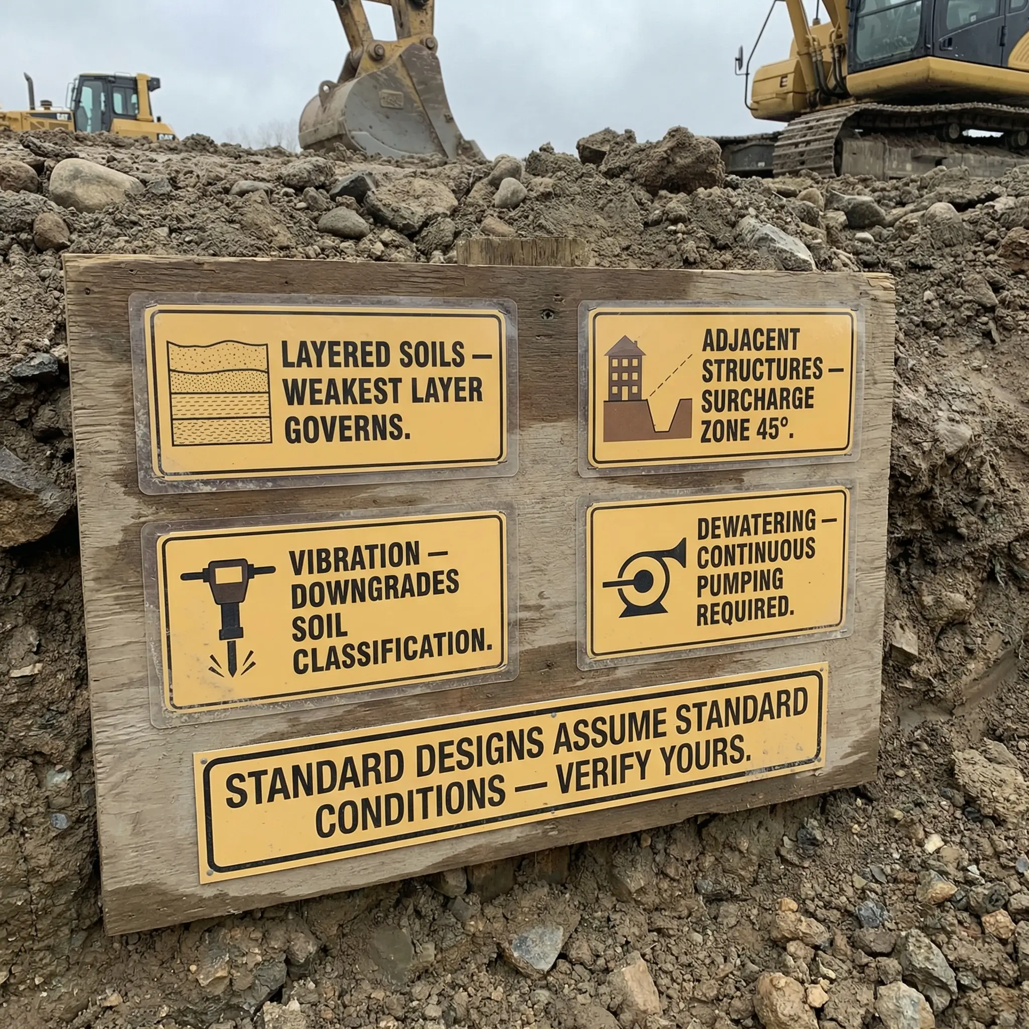
Standard Appendix B configurations assume relatively uniform, stable conditions: homogeneous soil, no significant water, no adjacent loads, no vibration, and moderate excavation durations. Real sites almost never match these assumptions perfectly. Several special conditions require either modified bench geometry, a switch to a different protective system, or a PE-designed solution.
Layered Soils and Mixed Strata
When an excavation cuts through multiple soil layers — a common condition on any site with geological variation or previous construction activity — the classification defaults to the weakest layer unless benching is designed by a PE who accounts for each layer individually. A typical scenario is a metre of cohesive clay (Type A) over a layer of sandy gravel (Type C). The surface layer looks stable. The underlying layer cannot hold a bench face. If the bench geometry is designed for Type A and the excavation reaches the Type C layer, the bench will fail from the bottom up.
- The field rule: Always investigate what lies below the current digging level. Review geotechnical bore logs if available. If no subsurface data exists and the excavation will exceed the current visible soil layer, assume the next layer is weaker until proven otherwise.
Adjacent Structures and Foundation Loads
Buildings, retaining walls, heavy equipment pads, and roadways adjacent to an excavation impose surcharge loads that the standard Appendix B configurations do not account for. These loads increase the lateral earth pressure on the bench face and can push it beyond its failure threshold even when the bench geometry meets OSHA dimensions. The zone of influence from an adjacent foundation typically extends outward at a 45-degree angle from the foundation base — meaning a structure 3 metres deep will influence the excavation soil for approximately 3 metres horizontally from the structure’s face.
- When adjacent loads exist within the zone of influence, a PE must design the benching system — Appendix B alone is not sufficient. This is one of the most commonly overlooked requirements in urban excavation work.
Vibration Sources
Pile driving, heavy traffic, blasting, compaction equipment, and even large excavators operating on the ground surface near the excavation edge generate vibration that reduces soil cohesion and can trigger bench face collapse. OSHA’s soil classification system explicitly addresses vibration — soil subject to vibration from any source cannot be classified as Type A, regardless of its compressive strength.
- Practical implication: If a Type A soil excavation with benching is located within the influence zone of a vibration source that starts operating after the excavation is open, the soil must be reclassified downward, and the benching geometry must be reassessed. I have seen this condition arise when piling work began on an adjacent lot two days after a benched excavation was completed and approved — requiring immediate re-evaluation.
Dewatering Conditions
When groundwater must be pumped from an excavation to allow work, the dewatering process itself can destabilise bench faces. Pumping draws water through the soil toward the pump intake, creating seepage forces that act on the bench face and can undermine its base. If the pump fails or is shut down overnight, water levels rise and re-saturate the bench face soil — creating the worst possible combination of weakened soil with full hydrostatic loading.
- On dewatered excavations with benching, the pump must run continuously during any period when workers are in the excavation, and the competent person must monitor water levels at the bench face — not just at the pump sump.
Benching vs. Other Protective Systems — When to Choose What
Benching is one tool in a four-tool excavation safety system. Selecting the right protective system — or the right combination — depends on soil conditions, excavation depth, available space, duration, adjacent hazards, and project logistics. No single system is best for every situation, and the worst excavation plans I have reviewed are the ones that defaulted to one method out of habit rather than analysis.
The following comparison reflects the practical trade-offs I evaluate when reviewing or approving excavation protective system selections on site.
| Factor | Benching | Sloping | Shoring | Shielding (Trench Box) |
|---|---|---|---|---|
| Soil type permitted | Type A, Type B only | All types (angle varies) | All types | All types |
| Additional equipment needed | None | None | Hydraulic struts, timber, soldier piles | Steel/aluminium trench box |
| Surface footprint | Large — increases with depth | Largest — requires most surface area | Minimal — near-vertical walls | Minimal — near-vertical walls |
| Installation speed | Fast (excavator cuts benches) | Fast (excavator cuts slopes) | Moderate to slow (installation required) | Moderate (crane or excavator to place box) |
| Best for | Wide excavations, foundations, basins | Open areas, rural sites, long runs | Deep narrow trenches, urban sites | Utility trenches, moving operations |
| Limitations | No Type C soil, large footprint, weather-sensitive | Enormous footprint at depth, impractical in congested areas | Requires trained installers, design per depth | Heavy equipment to move, limited width |
| Ongoing monitoring need | High — daily inspection required, weather-sensitive | Moderate — slopes generally more stable | Low to moderate — engineered system | Low — engineered, self-contained |
The decision matrix above is a starting point, not a substitute for site-specific analysis. On most projects, I find that the optimal approach combines methods — benching the upper portion of an excavation in competent soil, then using shoring or shielding at depth where the soil transitions to a weaker type or where the available surface footprint runs out.
Pro Tip: Never let the contractor’s equipment inventory drive the protective system selection. I have been on sites where the only reason benching was chosen was because the contractor did not own a trench box and did not want to rent one. The soil was Type C. The excavation was 12 feet deep. That is not a benching decision — that is a budget decision disguised as an engineering decision, and it can kill someone.
Inspection and Monitoring Protocols for Benched Excavations
A benched excavation is a dynamic system, not a static structure. The soil’s behaviour changes with time, weather, loading, and exposure. An excavation that passed inspection at 7 AM can become hazardous by noon if conditions change. Inspection is not a one-time sign-off — it is a continuous, shift-by-shift responsibility that directly prevents fatalities.
The competent person’s inspection protocol for a benched excavation should cover every factor that can degrade bench stability. The following checklist reflects the inspection items I have standardised across projects over the past decade.
- Bench face integrity: Examine each vertical bench face for signs of cracking, sloughing, bulging, or spalling. Any material that has fallen from the bench face onto the step below is evidence of active deterioration.
- Tension cracks: Look for cracks running parallel to the bench edge on the horizontal surface of each bench step and on the ground surface at the top of the excavation. Tension cracks indicate that the soil mass behind the bench face is beginning to separate — this is a pre-failure warning sign.
- Water conditions: Check for water seeping through the bench face, ponding on bench steps, rising groundwater at the excavation base, and any evidence of recent rainfall infiltration. Any water presence changes the analysis.
- Surcharge loads: Verify that spoil piles, equipment, materials, vehicles, and any other loads remain outside the minimum 2-foot setback zone. Check for loads that may have been placed since the last inspection — delivery trucks, pipe stockpiles, concrete forms.
- Bench geometry verification: Spot-check vertical face heights and step widths with a tape measure or laser level. Sloughing and erosion can gradually reduce step width and increase effective face height beyond compliant dimensions without anyone noticing.
- Soil condition changes: Compare current soil appearance and behaviour with the original classification. If a new soil layer has been exposed at greater depth, classify it. If previously dry soil is now wet, reassess the classification.
- Adjacent activity changes: Note any new vibration sources, adjacent excavation work, heavy equipment operations, or construction activities near the excavation that were not present during the previous inspection.
Best practice: On my projects, the competent person signs an inspection form at the start of every shift and after every weather event. The form is posted at the excavation access point. No signed form — no entry. This simple administrative control catches more missed inspections than any audit ever will.
Conclusion
Benching in excavation is deceptively simple in concept and unforgiving in execution. A stepped cut in the excavation wall is easy to visualise, easy to explain, and requires no specialised equipment — which is precisely why it is so often done wrong. The margin between a correctly designed bench and a fatal collapse is measured in feet of setback, degrees of angle, and the presence or absence of a competent person who actually knows what those numbers mean and has the authority to enforce them.
Every benching failure I have investigated shared the same pattern: someone skipped the soil classification, ignored the water, eyeballed the bench height, or placed a load too close to the edge. Not one of those failures involved exotic geology, unprecedented weather, or unforeseeable conditions. They were all preventable with the knowledge, tools, and discipline that OSHA Subpart P demands — and that every excavation crew has access to if the project leadership makes it a priority.
The soil does not read your excavation plan. It does not care about your schedule. It responds to physics — load, shear strength, water pressure, and geometry. Get the classification right, cut the benches to the prescribed dimensions, keep the loads back from the edge, inspect every shift, and stop the work when conditions change. Those five disciplines are the difference between a compliant excavation and a body recovery. There is no version of faster or cheaper that justifies trading a worker’s life for a missed soil test.