
TL;DR — Key Numbers
- ~74% of falsework collapses occur during concrete placement (Engineering Failure Analysis, 1987) — the phase with the densest workforce exposure both above and below the structure.
- 80% of 96 OSHA-investigated structural collapses traced to construction errors, not design flaws (US OSHA Directorate of Construction, 1990–2008 dataset).
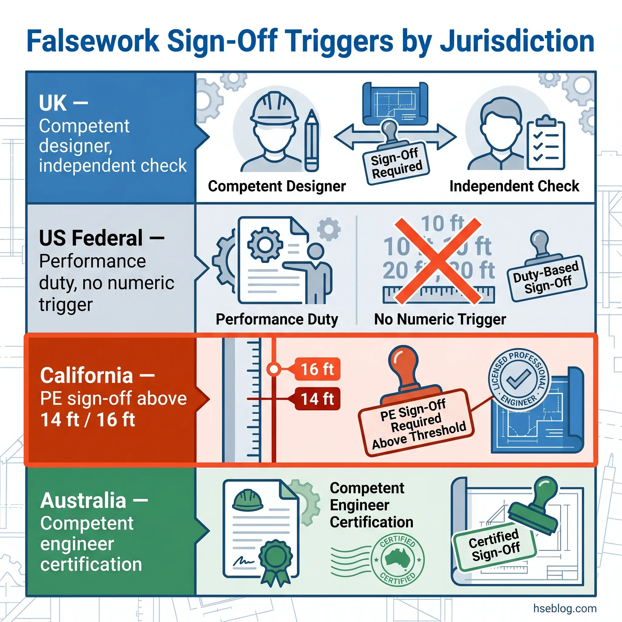
- Cal/OSHA §1717 triggers registered civil engineer sign-off where falsework exceeds 14 ft in height, 16 ft span, or traffic passes beneath; federal OSHA 1926.703 sets no numeric threshold — only a performance duty.
- £100,000 HSE fine against Matrod Frampton Ltd at Bristol Magistrates’ Court (HSE Media Centre, 16 December 2025) for absence of a temporary works procedure — reported under CDM 2015 Regulations 13(1) and 19(1).
Falsework safety is the temporary load-bearing structure supporting freshly placed concrete, precast units, or steelwork until the permanent structure can carry itself. It demands a written design, an independent check, staged inspection against that design, and written authorisation at each handoff — load, use, and dismantling. Most documented collapses happen during the pour.
On 16 December 2025, the UK Health and Safety Executive announced that Bristol Magistrates’ Court had fined Matrod Frampton Ltd £100,000, plus £8,242 in costs and a £2,000 victim surcharge, after a 2022 wall collapse caused life-changing injuries to a 69-year-old worker (HSE Media Centre, 2025). The prosecution ran under CDM 2015 Regulations 13(1) and 19(1). HSE Inspector Alexander Ashen’s central point, restated in the release, was that no temporary works procedure was in place.
Falsework sits where a single managerial gap — a missing design brief, an unchecked proprietary calculation, a skipped permit — converts routine work into a life-critical failure. The published research is blunt: approximately 74% of falsework failures occur during concrete placement (Engineering Failure Analysis, 1987), the window when workforce density peaks above and below the structure. This article walks the three legs of falsework safety — design, inspection, and risk — as one connected governance chain across UK, US, EU, and Australian obligations.
What is falsework, and why is it one of construction’s highest-risk temporary works?
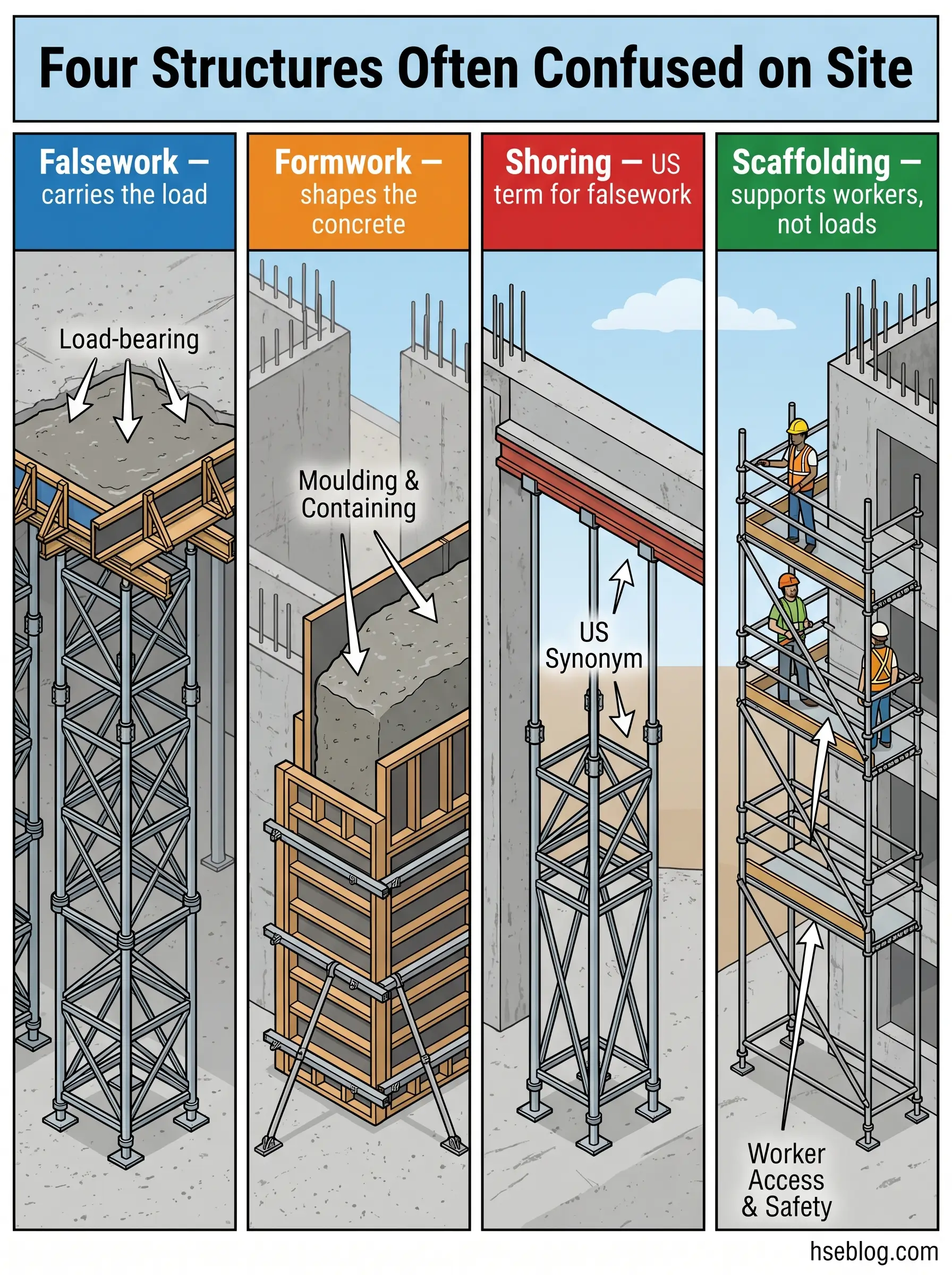
Falsework carries the weight of a building before the building can carry itself. US federal OSHA 29 CFR 1926.700 defines it as the total system of support for freshly placed or partially cured concrete, including the mould or sheeting and all supporting members. UK practice aligns with this under BS 5975-1:2024, which classifies falsework as temporary works governed by the same management procedures as any other load-bearing interim structure.
Three terms get tangled in daily site speech: falsework, formwork, and shoring. Formwork is the mould that gives concrete its shape. Falsework is the load-bearing structure beneath the formwork, transferring wet-concrete weight, construction surcharge, and dynamic effects down to the ground. Shoring is the US-preferred synonym for falsework, although it also refers to propping of existing structures in demolition or refurbishment contexts. Access scaffolding is something different entirely — designed for workers and light materials, not for structural load transfer.
That distinction matters because access scaffold components keep appearing in falsework collapses. A consistent pattern in published Cal/OSHA citations and CROSS-Safety reports is the misuse of standard access frames as vertical shoring for a wet slab. Visually similar, structurally mismatched.
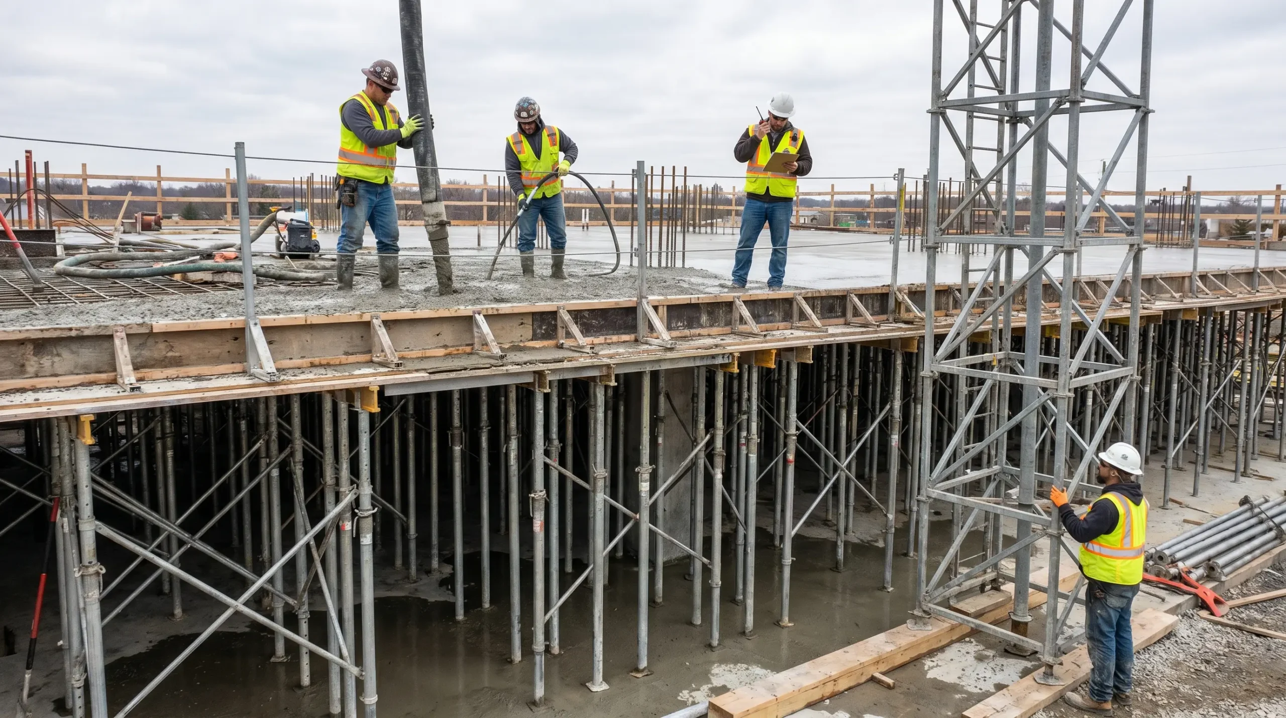
The reason falsework sits at Elevated YMYL risk is the loading profile. Unlike permanent works, falsework is routinely designed to around 90% of component capacity over short service lives with minimal redundancy. Failure is therefore sudden rather than progressive, and it concentrates in the placement window — when the pour crew, finishers, pump operators, and rebar fixers are clustered around and often beneath the deck. The research finding of approximately 74% of falsework collapses occurring during concrete placement (Engineering Failure Analysis, 1987) reflects exactly this exposure concentration.
This article provides general HSE knowledge. Life-critical temporary works — including falsework design, independent checking, and permit-to-load authorisation — must be planned and supervised by a competent person with relevant training, jurisdiction-specific authorisation, and site-specific risk assessment. The information here does not replace that.
Falsework design principles: loads, stability, and the design brief
BS 5975-2:2024 sets the UK code of practice for falsework design, replacing Section 3 of the withdrawn BS 5975:2019 from 17 December 2024 (BSI Knowledge, 2024). The standard integrates with BS EN 12812:2008 for Class B1 and B2 limit-state design, while keeping permissible-stress methods available for Class A work. Under US federal law, 29 CFR 1926.703(a)(1) imposes a performance duty: formwork must be designed, fabricated, erected, supported, braced, and maintained to carry all intended loads without failure.
Competent falsework design accounts for five load categories, not just the weight of wet concrete. Dead loads include formwork, reinforcement, and the concrete itself. Imposed loads cover workers, tools, pumps, and stockpiled materials. Environmental loads include wind and, in cold climates, snow and ice. Indirect loads arise from thermal movement, differential settlement, and propping reactions from adjacent structures. Dynamic effects come from placement rate, vibration, and pump surge.
A signature omission in design review is wind. HSE’s Investigation into aspects of falsework (HSE Contract Research Report 394/2001) found that wind loading on partially enclosed or exposed falsework frequently gets left out of the calculation package, particularly for medium-height work where designers assume wind has no purchase. That assumption is wrong when cladding is partially fitted or when the falsework stands above obstruction level.
The 2.5% lateral stability rule
Jurisdiction Note: UK practice under BS 5975 recommends that falsework be designed for a horizontal force equal to 2.5% of the total vertical load, acting at the point of application, to account for erection tolerance and workmanship imperfections. The rule traces to the Bragg Report following the 1972 Loddon Viaduct collapse that killed three operatives (CROSS-Safety, 1975). It is a stability allowance — it does not substitute for a wind calculation. Designers working to BS EN 12812 Class B1/B2 apply limit-state equivalents, but the underlying Bragg logic remains the quiet reason large UK falsework collapses have not repeated at the 1972 scale.
The design brief is the document most often missing when prosecutions follow. It captures scope, loads, interfaces with permanent works, erection sequence, dismantling sequence, and tolerances. Without it, a proprietary supplier’s table of allowable loads — which assumes idealised verticality, plumb sills, and concentric loading — gets applied directly to a site where none of those assumptions hold.
Falsework design classes and standards across jurisdictions
No single standard governs falsework design worldwide, and the differences are sharp enough that cross-border project teams regularly misapply them. A project designed to BS 5975-2:2024 in London does not meet Cal/OSHA §1717 in Oakland without additional engineering sign-off. A design compliant with federal OSHA 1926.703 may fall short of the numeric thresholds that apply once the work crosses into California.
The UK standards split into two parts as of late 2024. BS 5975-1:2024 covers management procedures for temporary works — duty holders, design brief, independent check, permit controls. BS 5975-2:2024 covers falsework design and implementation — load cases, stability, erection, use, and dismantling. Non-designers generally need Part 1 only; designers work to both in parallel with BS EN 12812:2008.
| Jurisdiction | Primary Standard | Design Sign-Off Trigger | Design Method |
|---|---|---|---|
| UK | BS 5975-1:2024 + BS 5975-2:2024 | Competent designer; independent check proportionate to complexity | Permissible stress (Class A); limit state (Class B1/B2) |
| EU / International | BS EN 12812:2008 | Class-based (A, B1, B2) | Class A: known component performance; B1/B2: limit state |
| US Federal | 29 CFR 1926.703 | Performance duty; no numeric threshold | Designer’s choice; ANSI A10.9 deemed compliant |
| US California | Title 8 CCR §1717 | CA-registered civil engineer signs above 14 ft height, 16 ft span, or traffic beneath | Minimum 100 psf combined live + dead |
| Australia | Safe Work Australia Guide to Falsework + AS 3610 | Competent engineer certification | AS 3610 series |
BS EN 12812:2008 defines three classes. Class A is simple falsework relying on the known performance of its components — in UK practice, designed to BS 5975. Class B1 is fully detailed limit-state design. Class B2 is limit-state design oriented to prefabricated proprietary equipment.
The commonly-missed nuance is that federal OSHA 1926.703 does not replicate Cal/OSHA’s numeric triggers. Crews moving between states routinely carry the wrong assumption in either direction — either that Cal/OSHA’s 14-ft threshold applies on a Texas job where it does not, or that federal OSHA lets them skip engineering sign-off entirely on a California job where it does not. The stricter jurisdictional reference should govern where work spans both.
Who is responsible? Duty holders in the falsework chain
The failure signature in HSE prosecutions and Cal/OSHA citations is rarely a missing role on paper. It is a role occupied in name but without the authority, presence, or competence to stop work when the pour is about to start and something has slipped. BS 5975-1:2024 tightened the language around competent-person appointment precisely because this gap kept recurring across the published record.
UK duties follow CDM 2015 and BS 5975-1:2024 in parallel. The client, principal designer, principal contractor, designer, and contractor each carry defined obligations. The principal contractor typically appoints a Temporary Works Coordinator (TWC) — often a chartered civil or structural engineer on complex schemes — whose authority explicitly includes halting unsafe work. A Temporary Works Supervisor (TWS) may be appointed for site-level oversight reporting to the TWC. The TWC concept itself originated in Bragg Committee recommendations after Loddon Viaduct and has been the central UK control mechanism since BS 5975:1982.
US federal duty structure is flatter. 29 CFR 1926.703(b)(3) places the inspection duty on a competent person — someone capable of identifying existing and predictable hazards and authorised to take prompt corrective action. Design sits with a qualified person; above the Cal/OSHA thresholds noted earlier, that qualified person must be a California-registered civil engineer. Federal OSHA does not name a TWC role.
| Role | UK Anchor | US Federal Anchor |
|---|---|---|
| Overall temporary works control | TWC — BS 5975-1:2024 | Competent person — 1926.703(b) |
| Site-level oversight | TWS — BS 5975-1:2024 | Competent person (same) |
| Design | Temporary works designer — CDM 2015 | Qualified person (PE in California above threshold) |
| Independent check | Design checker — BS 5975-1:2024 | Not specifically named; required where qualified person determines |
Interface responsibility is the quietly decisive duty. The permanent works designer must review and comment on falsework proposals where those proposals affect or rely on the permanent structure — for example, where the falsework load path anchors into or rests against partially-completed concrete. When that review is skipped, falsework gets erected against assumptions the permanent designer never signed off on.
Falsework inspection: what to check, when to check, and who certifies
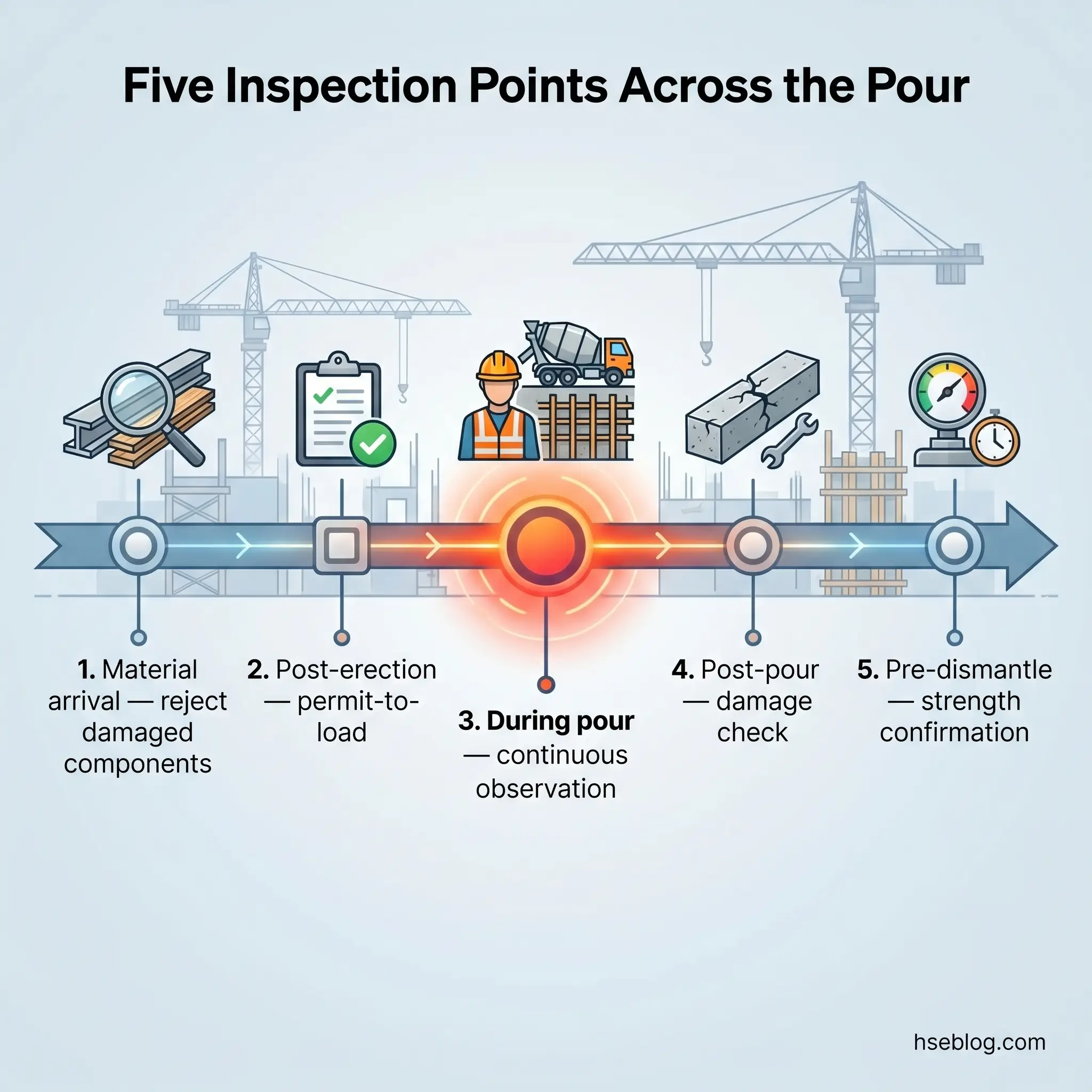
Federal OSHA 29 CFR 1926.703(b)(3) requires shoring inspection at three distinct moments: immediately prior to, during, and immediately after concrete placement. Those are legal anchors, not best practice. Read across to BS 5975-1:2024 and the picture extends further — inspection is a staged lifecycle running from material arrival to permit-to-dismantle.
Pre-erection material inspection comes first. 1926.703(b)(1) and (b)(2) prohibit the use of damaged, bent, or corroded shoring components. The practical reading of this clause is that the competent person rejects not only visibly damaged pins, base plates, and standards but also any component without traceable provenance where the manufacturer’s load data cannot be matched to the actual item on the deck.
Post-erection, pre-load inspection verifies that the as-built falsework matches the approved design drawings. In UK practice under BS 5975-1:2024, this is where the permit-to-load is issued — a written authorisation that triggers concrete placement. Cal/OSHA §1717 requires a written certification of pre-pour conformity inspection, with the falsework plan available at the jobsite at all times.
Key inspection checkpoints at each stage
The during-pour window is where most collapses occur, and also where most inspection effort disappears. A practical observer watches for these throughout the pour:
- Settlement of the sills or bearing — tell-tales, string lines, or optical levels measuring deflection in real time.
- Plumb of standards — visible lean developing as load ramps up, particularly at the pour face.
- Bracing tightness — pin and wedge connections, clamp torque, and cross-bracing integrity.
- Unplanned surcharge — rebar stockpiles, skip loads, pump line movements not covered in the design brief.
- Communication line — radio or direct line to the foreman with authority to stop the pour.
Watch For: The inspection that gets skipped on tight programmes is the during-pour observation. Teams inspect beforehand, issue the permit-to-load, and withdraw to other tasks once the pump starts. That is exactly the pattern in which a small bracing deficiency becomes progressive collapse as concrete surcharge hits. An observer without authority to stop the pour is not an observer — they are a witness.
Post-pour inspection checks for damage or weakening caused by the placement itself. Under 1926.703(b)(5), shoring weakened below design capacity must be immediately reinforced. Pre-dismantle confirmation closes the loop: the competent person verifies in writing that the permanent structure has reached design strength before any falsework is struck.
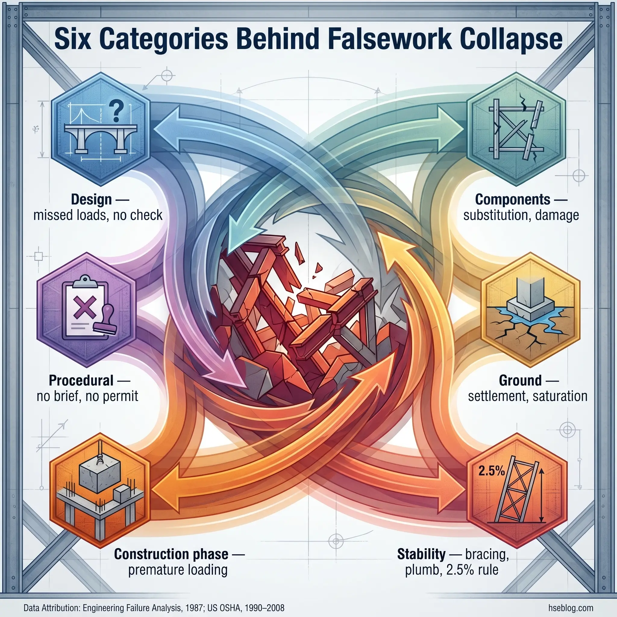
Why falsework fails: the recurring risk categories
Roughly 74% of documented falsework collapses happen during concrete placement (Engineering Failure Analysis, 1987), and 80% of OSHA-investigated structural collapses from 1990 to 2008 were attributed to construction errors rather than original design flaws (US OSHA Directorate of Construction). Those two numbers, read together, reframe the whole question. Most falsework collapses are not exotic. They sit inside six recurring categories that compound on each other.
Design-side failures. Inadequate load assumptions, omitted wind loading, unchecked calculations, and geometry mismatches between the design and the as-built. A CROSS-Safety published report documented a tank falsework collapse where translated calculations referred to a different tank diameter than the one being built — a cross-check failure that would have been caught by an independent design check proportionate to complexity.
Component failures. Under-strength pins, incorrect material substitution, reused shores with hidden damage, and connectors not positively locked. This is the category where access scaffold components appear inside load-bearing shoring — visually similar, structurally mismatched, forbidden by 1926.703(b)(1).
Foundation and ground failures. Soft or saturated bearing, differential settlement, timber sole plates immersed in standing water, uncompacted sub-base. The HSE Contract Research Report 394/2001 recurrently surfaced poor ground assessment as a root cause — designers using supplier tables that assumed a rigid bearing surface on sites where the bearing surface was anything but.
Stability failures. Missing or incomplete bracing in one axis, standards out of plumb beyond tolerance, and loss of the 2.5% lateral restraint capacity from cumulative small errors. Stability failures are the quiet category because the falsework looks fine until it doesn’t.
Construction-phase failures. Premature loading before concrete strength gain, unplanned concentrated loads from rebar stockpiles or pump line movement, dynamic impact during placement. 1926.703(e)(1)(i) and (ii) explicitly prohibit removing forms and shores until the concrete has attained sufficient strength to support its weight and superimposed loads.
Procedural failures. No design brief, no independent check, no TWC appointed with real authority, no permit-to-load, no during-pour observer. The Matrod Frampton prosecution (HSE Media Centre, 2025) and the 2017 Oakland formwork collapse — which resulted in $147,315 in Cal/OSHA penalties across three contractors and hospitalised 13 workers — both sat fundamentally in this category.
The categories compound. Reviewing the public record, single-cause falsework collapses are rare. Most involve two or three simultaneous failures: a design assumption that never accounted for wind, a component substitution that wasn’t flagged, and a missing during-pour observer who would have seen the lean before it reached failure.
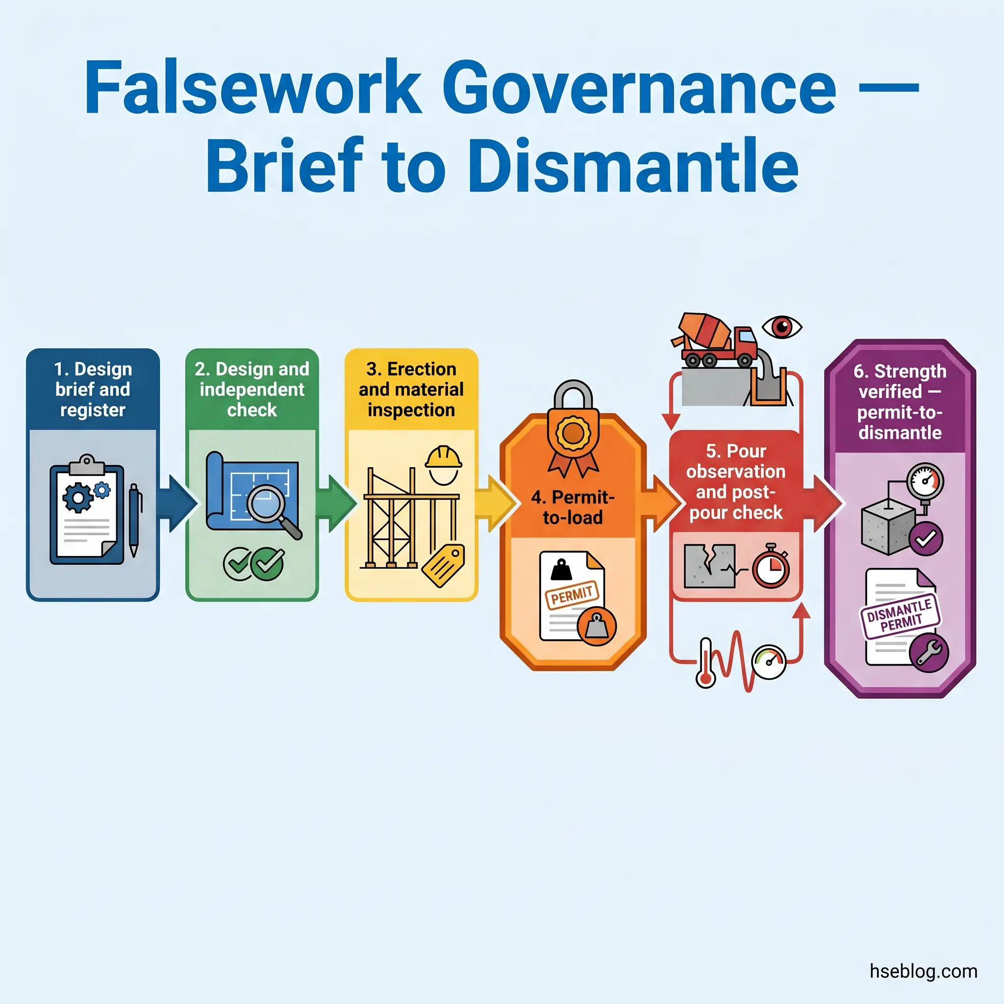
Controlling the risk: from design brief to permit-to-dismantle
On a well-governed site, falsework safety reads as a chain of written handoffs, not a checklist pinned to a wall. Each handoff forces someone with defined authority to confirm a defined condition before the next phase starts. The chain is the control. Where any single link is skipped, the whole chain loses the property that makes it safe.
The governance sequence, drawn from BS 5975-1:2024 management procedures and cross-referenced against 1926.703 and Cal/OSHA §1717:
- Temporary works register — every falsework scheme logged with its design category and designer.
- Design brief — scope, loads, interfaces with permanent works, erection and dismantling sequence, tolerances.
- Design and design risk assessment — by a competent designer; Class A to BS 5975, Class B1/B2 to BS EN 12812 limit-state methods; in California, signed by a registered civil engineer above §1717 thresholds.
- Independent design check — proportionate to complexity; a core Bragg Report recommendation retained in BS 5975-1:2024.
- Pre-erection material inspection — reject damaged or untraceable components per 1926.703(b)(1)–(2).
- Erection under competent supervision — to the approved drawings.
- Permit-to-load — written authorisation after as-built verification; the single most effective control in the chain.
- During-pour observer — continuous monitoring, communication means, authority to stop placement.
- Post-pour inspection — damage and weakening check per 1926.703(b)(5).
- Strength verification of permanent structure — written confirmation before dismantling.
- Permit-to-dismantle — issued by the competent person; dismantling generally in reverse order of erection.
Audit Point: The permit-to-load is where auditors often find the governance chain broken. Ask to see the permit, the design drawings it references, and the as-built verification that supported its issue. Where the permit is pro-forma — signed in advance, signed by someone without authority to verify, or signed after the pour started — the rest of the chain has no structural meaning. This is the single document most predictive of whether the scheme was genuinely governed.
The procedural controls outlined in the UK HSE guidance on temporary works align closely with this sequence. In the US, the Cal/OSHA §1717 requirement that the falsework plan be available at the jobsite at all times functions as the documentary anchor to the same chain, even without a formal UK-style permit system.
Dismantling falsework: the forgotten risk phase
Dismantling is the phase that most generic guidance treats as an afterthought. It isn’t. Striking falsework before the permanent structure is self-supporting is a distinct failure mode, and removing the wrong element first redistributes loads in ways the design never contemplated. Programme pressure to recover components for the next pour drives the behaviour; the consequences land on whoever is underneath.
29 CFR 1926.703(e)(1) is unambiguous: forms and shores shall not be removed until the concrete has gained sufficient strength to support its weight and any superimposed loads. That strength determination, under 1926.703(e)(1)(ii), must come from either compliance with the plan’s specified conditions or from concrete compressive strength tests. ASTM C873 field-cured cylinders and maturity methods provide defensible strength evidence; calendar-based rules of thumb do not.
Reshoring is the other control that gets compressed. 1926.703(b)(6) requires reshoring to be erected as original forms and shores are removed, wherever the concrete is required to support loads in excess of its capacity at that age. Reshoring is not optional on multi-level work with tight pour cycles — it is the mechanism that keeps newly-cast slabs from carrying floors above before they are ready.
The dismantling sequence:
- Strength verification in writing before any removal (1926.703(e)(1)(ii)).
- Reverse-order dismantling aligned to the designer’s dismantling sequence in the design brief.
- Reshoring in place where the concrete cannot yet carry construction loads above.
- Remove formwork before falsework where practicable for in-situ concrete, so the slab sheds its direct mould load before the supporting structure is disturbed.
- Clear protruding nails and ties, controlled stockpiling (1926.703(e)(2)).
Frequently Asked Questions
The Operational Summary
Four decisions shape whether a falsework scheme stays governed or drifts into the failure record. First, whoever signs the design must be competent for the class of work and jurisdictionally authorised — BS 5975-2:2024 for UK Class A, BS EN 12812 for Class B1/B2, a California-registered civil engineer above Cal/OSHA §1717 thresholds, or the equivalent qualified person under federal 1926.703. Second, an independent design check proportionate to complexity must happen before any steel or prop arrives on site.
Third, the permit-to-load must be a genuine written handoff, not a pro-forma signature. It anchors the entire governance chain — without it, the design and the placement are not connected by anything auditable. Fourth, the during-pour observer must have real authority to stop placement, and must remain in position from first concrete to last. The HSE prosecution record, including the Matrod Frampton fine of £100,000 in December 2025, shows that where these four conditions hold, catastrophic collapse is preventable; where any one fails, the published incident pattern repeats with grim consistency.
Treat falsework safety as a single chain running from design brief to permit-to-dismantle, with jurisdiction-specific anchors at every link. That framing — not another checklist — is what separates schemes that hold from schemes that make the next prosecution headline.
Regulatory content here reflects general HSE professional understanding of UK, US federal, California, and Australian requirements as of April 2026. It is not legal advice. Specific compliance questions, enforcement situations, or prosecution risk should be directed to qualified legal counsel in the applicable jurisdiction.