
TL;DR
- 5 ft / 1.5 m (US) vs 1.2 m (UK practice). OSHA triggers protective-system requirements at 5 ft; UK HSE guidance treats 1.2 m as the practical benchmark — the stricter reference is the safer default (OSHA 29 CFR 1926.652; HSE UK).
- 20 ft (6.1 m). Beyond this depth, OSHA requires a Registered Professional Engineer to design the protective system — tabulated data alone is not permitted (OSHA 29 CFR 1926.652(b)(1)(ii)).
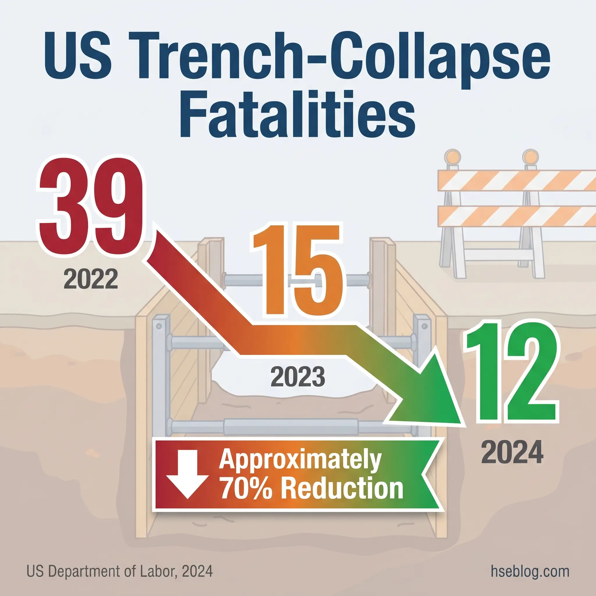
- 39 deaths in 2022 → 12 in 2024. US trench-collapse fatalities fell roughly 70% under OSHA’s zero-tolerance enforcement through the Trenching National Emphasis Program (US Department of Labor, 2024).
- 3 design-check categories. BS 5975-1:2024 mandates CAT 1 (restricted), CAT 2 (independent), CAT 3 (separate-organisation) checks — complexity drives which applies (BSI, 2024).
Propping and shoring safety procedures require a designed temporary-works system matched to actual site conditions, installation by trained workers, daily inspection by a competent person, and controlled dismantling in the designer’s specified sequence. OSHA 29 CFR 1926 Subpart P governs US trench work; BS 5975-1:2024 and CDM 2015 govern UK temporary works procedurally. Both frameworks treat designed sign-off as mandatory, not optional.
Competent-Person Caveat: This article provides general HSE knowledge on propping and shoring safety procedures. Life-critical work — trench shoring, façade retention, falsework under concrete loads, structural dead- and flying-shore installations — must be planned by a competent temporary-works designer or Registered Professional Engineer, and supervised on site by a competent person with stop-work authority. Nothing here replaces site-specific design, risk assessment, or trained supervision.
In fiscal year 2024, federal OSHA investigated 826 worker deaths across all US industries — an 11% reduction from 928 the previous year and the lowest non-COVID investigated fatality count since 2017 (US Department of Labor, 2024). Inside that number sits a shift temporary-works professionals should read carefully: trench-collapse fatalities fell from 39 in 2022 to 15 in 2023 to 12 in 2024, a roughly 70% decline the agency attributes to enforcement under its Trenching National Emphasis Program (US Department of Labor, 2024). The gains are real, but they rest on a narrow margin — every one of those 12 deaths occurred in a trench where the rules already existed.
That is the honest frame for this subject. Propping and shoring failures are rarely failures of unknown engineering. They are failures of known controls — soil misclassified, design-check skipped, props installed by crews who never read the scheme, permits signed without a walk-down. This article lays out the safety procedures that keep the system working on a live site: the standards that govern the work, the design and inspection duties that precede the first prop, the installation and dismantling rules that decide whether the structure holds, and the recurring failure patterns investigators keep finding when it doesn’t.
What Propping and Shoring Mean in a Safety Context — And Why They Are Not the Same
Language matters here because it drives expectations. Propping usually refers to load-bearing support — most often vertical — provided to formwork, slabs, beams, or openings cut through existing structures. Shoring covers a broader family: any temporary support, vertical or lateral, used to hold ground, façades, or buildings while other work proceeds. Every system in both categories falls within the legally defined class of temporary works under the Construction (Design and Management) Regulations 2015 in the United Kingdom, and is regulated under 29 CFR 1926 Subparts P (excavations) and Q (concrete and masonry) in the United States.
The safety significance runs deeper than vocabulary. Temporary works fail at rates disproportionate to their apparent simplicity because teams treat them as provisional — something between proper engineering and site improvisation. BS 5975-1:2024 treats the temporary-works register as a live control document precisely because temporary works move, settle, get reconfigured, and absorb new loads while permanent works are held to drawings and never touched again.
One practical consequence: proprietary props, shores, and panels — Acrow-style telescopic steel props, modular shoring towers, trench boxes — are often treated as standard solutions that need no site-specific verification. HSE’s explicit position, and the position of any competent temporary-works designer, is the opposite. Even a proprietary system requires load assessment, bearing checks, and a configuration designed for this specific site.
| Term | What it supports | Primary standards |
|---|---|---|
| Propping | Vertical loads — slabs, beams, openings | OSHA 1926.703; BS EN 1065 |
| Shoring | Vertical or lateral — soil, façades, walls | OSHA 1926 Subpart P; BS 5975 |
| Falsework | Full temporary support to wet concrete and permanent structure | BS EN 12812; BS 5975-2:2024 |
| Formwork | The mould that shapes concrete | ACI 347; OSHA 1926.703 |
The Regulatory Framework: OSHA, HSE, and the Standards That Apply
The framework most multinational contractors get wrong is the one where OSHA and HSE run in parallel. US rules are a federal statute — enforceable, citation-driven, with injuries and fatalities tracked at the site level. The UK architecture layers statute (the Health and Safety at Work etc. Act 1974 and CDM 2015) over British Standards (BS 5975 series) that act as the practical benchmark for reasonably practicable compliance. HSE inspectors routinely use BS 5975 as the test for whether a duty-holder has done what the Act requires — so treating a British Standard as optional is a misread of how enforcement works in practice.
In the United States, 29 CFR 1926 Subpart P governs trench and excavation work, with Appendices A–F providing soil classification (A), sloping and benching (B), timber shoring tables (C), aluminium hydraulic shoring tables (D), and selection of protective systems (F). For concrete formwork, 1926.703 requires formwork to be designed, fabricated, erected, supported, braced, and maintained so that it will support all reasonably anticipated vertical and lateral loads without failure. The competent-person requirement in 1926.650–652 runs underneath both.
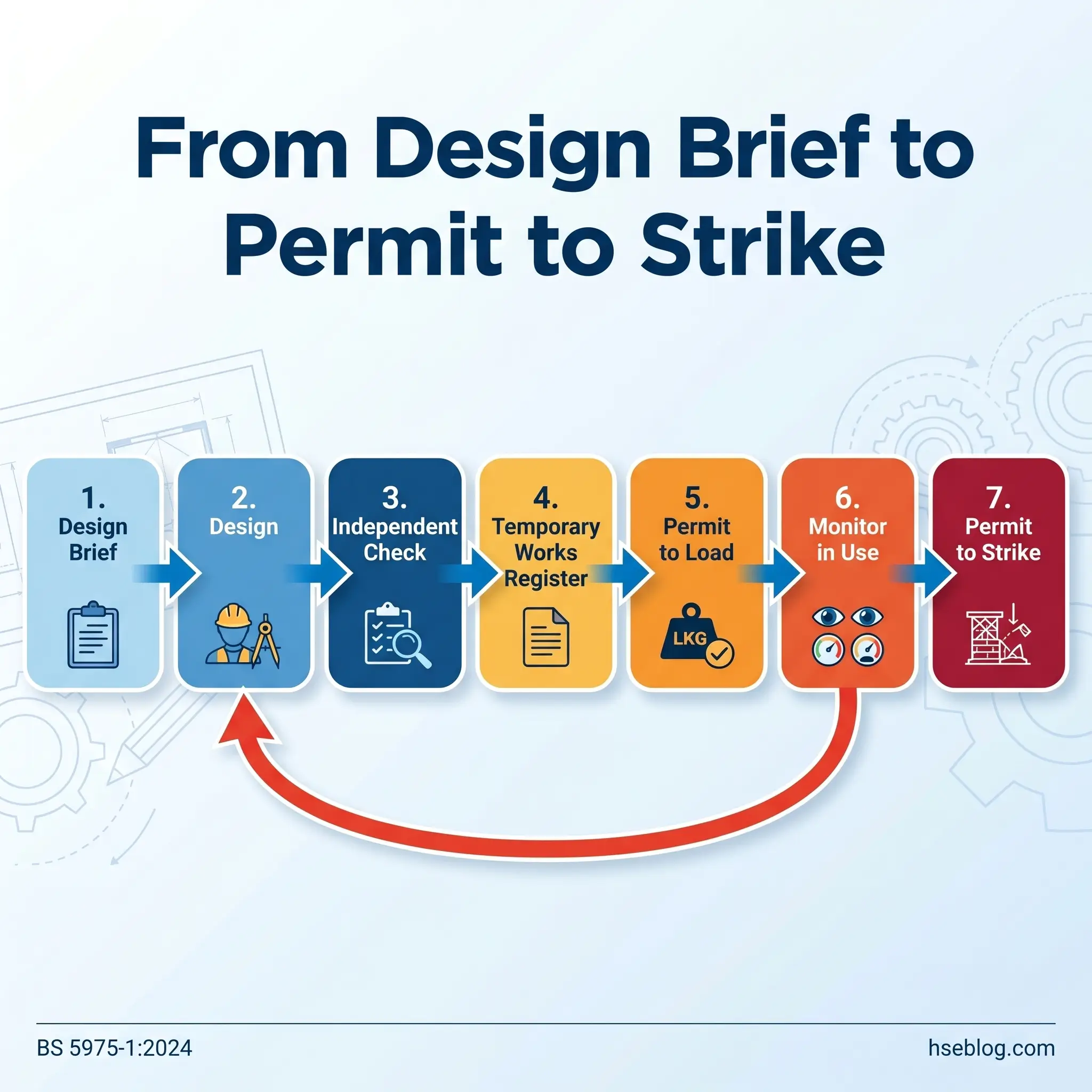
In the United Kingdom, CDM 2015 places duties on the client, principal designer, principal contractor, and designers — including an explicit obligation on permanent-works designers to consider temporary works. BS 5975-1:2024 sets the procedural framework: appointment of a Temporary Works Coordinator (TWC), a Temporary Works Register, a design brief checked against design-check CAT 1/2/3, and Permit to Load and Permit to Strike as live controls. BS 5975-2:2024 sets the technical design requirements for falsework.
For European and CE-marked equipment, BS EN 1065 classifies adjustable telescopic steel props into classes A through E by load capacity, and BS EN 12812 defines three falsework classes (A, B1, B2) with escalating design rigour. Any proprietary prop used on a UK or EU project should carry the correct EN 1065 class marking, and the design must use that classification, not a generic “steel prop” assumption.
Key Regulatory Thresholds at a Glance
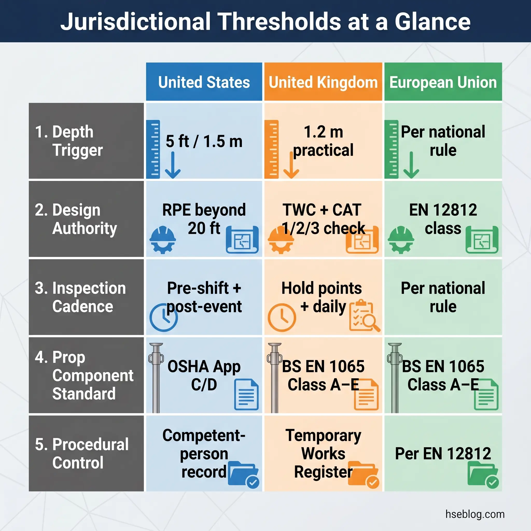
Three numbers decide most arguments on a propping and shoring job. The first is the depth trigger. OSHA mandates a protective system at 5 ft (1.5 m), unless the excavation is entirely in stable rock (29 CFR 1926.652(a)(1)). UK guidance treats 1.2 m as the practical threshold below which a cave-in can still kill — which makes 1.2 m the stricter default for any multinational contractor.
The second is the design-authority threshold. OSHA permits use of tabulated data (Appendix C for timber, Appendix D for aluminium hydraulic shores) up to 20 ft (6.1 m); beyond that, the design must come from a Registered Professional Engineer (29 CFR 1926.652(b)(1)(ii)). The UK does not use a single depth threshold — design authority is a function of complexity via the CAT 1/2/3 check system under BS 5975-1:2024.
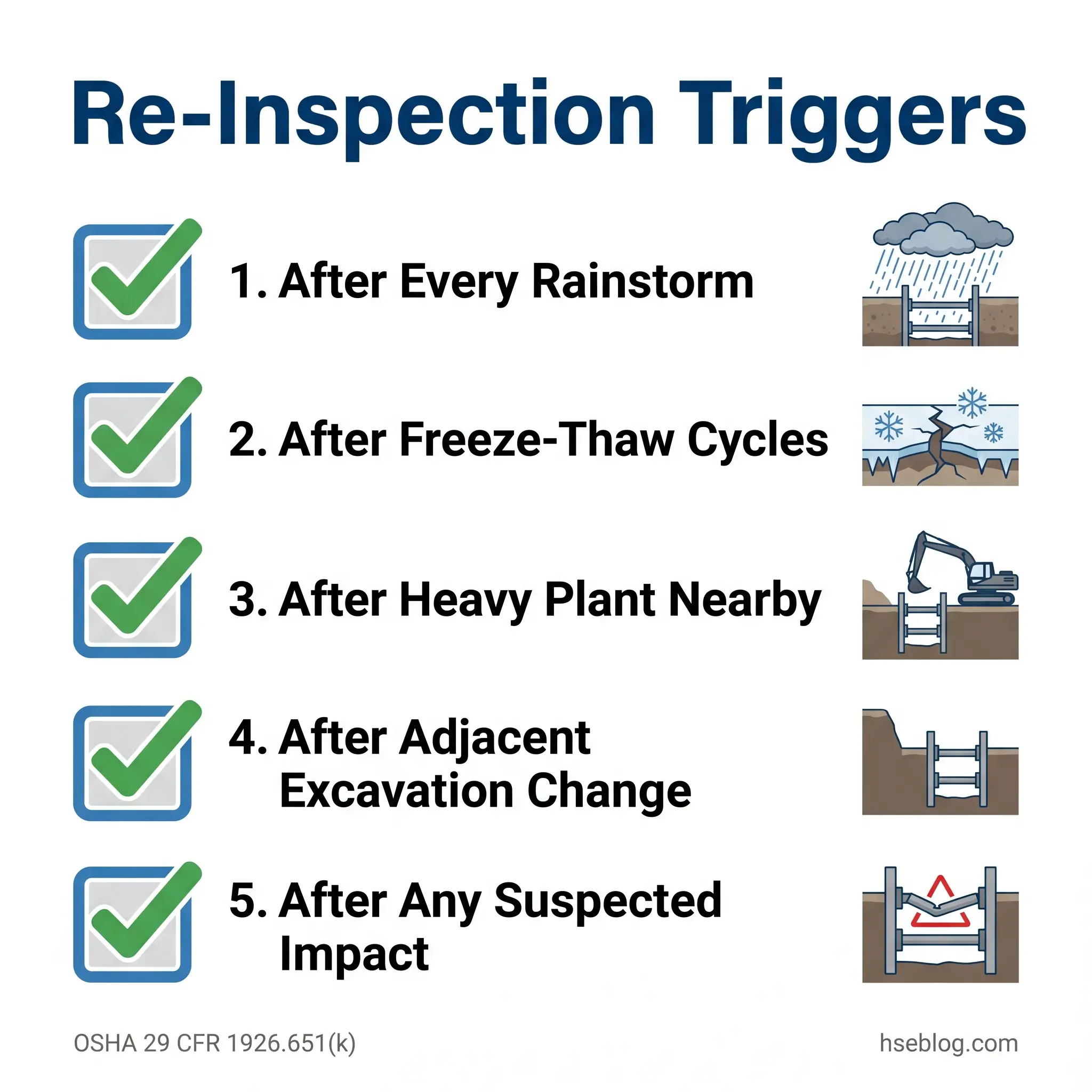
The third is inspection cadence. OSHA requires inspection by a competent person before each shift, after every rainstorm, and after any other occurrence that could increase the hazard (29 CFR 1926.651(k)). UK practice layers daily checks over formal hold-point inspections tied to the Permit to Load and the Temporary Works Register.
Types of Propping and Shoring Systems Used on Construction Sites
Before procedures make sense, the families need to be clean in the reader’s head. These systems do genuinely different jobs, and conflating them is where most of the confusion in competitor content begins.
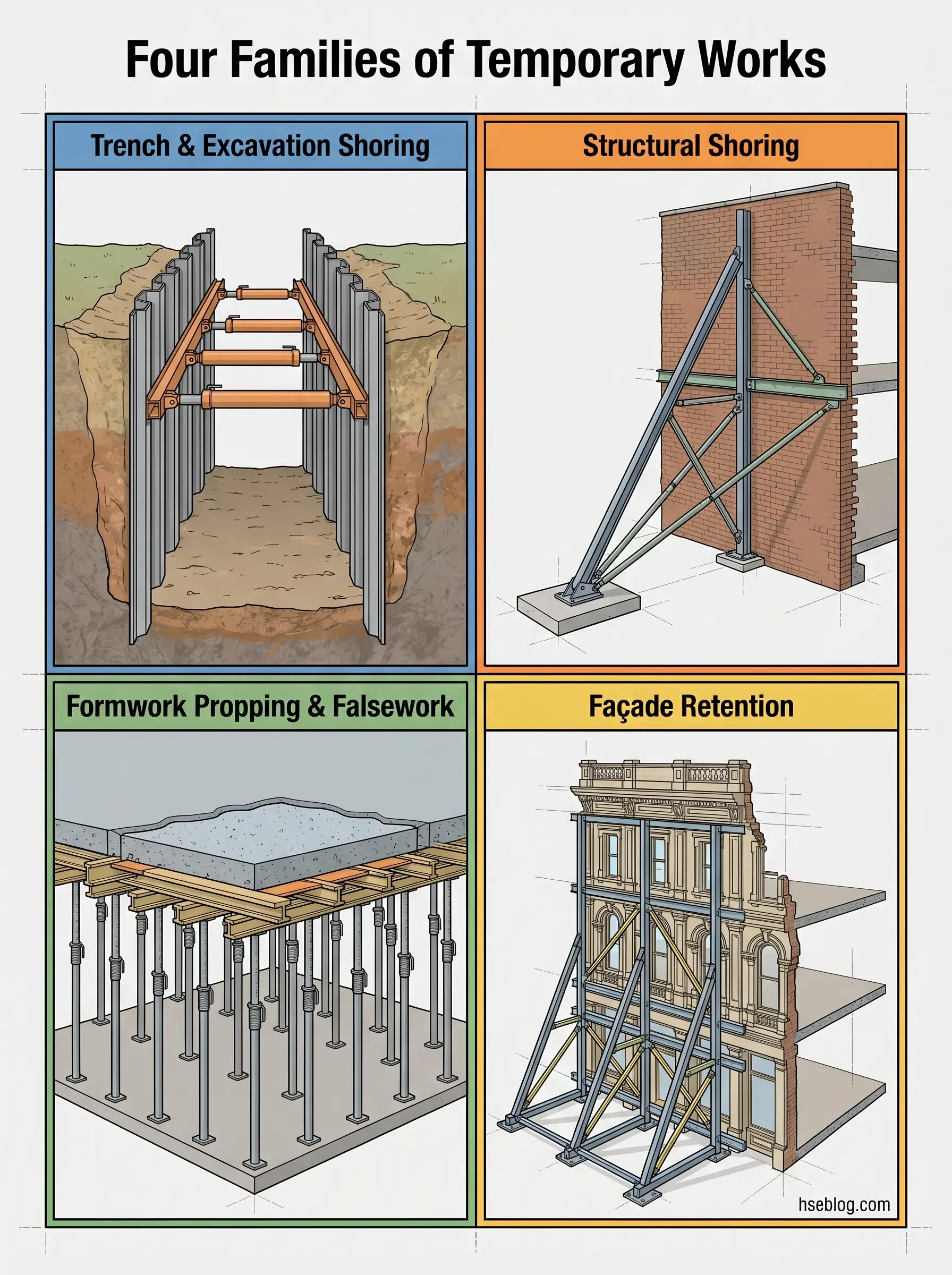
Trench and excavation shoring covers systems that hold back soil to prevent a cave-in: timber shoring (wales, uprights, cross-braces designed per OSHA Appendix C), aluminium hydraulic shores (Appendix D), soldier piles with lagging for deeper or more complex excavations, and sheet piling. A trench box — sometimes called a trench shield — is technically protection rather than shoring: it does not prevent a cave-in, it protects the worker inside it if one occurs. OSHA treats shoring and shielding as distinct protective strategies under 1926.652, and the selection carries different residual-risk implications that the competent person must understand.
Structural shoring covers temporary supports that hold existing structures while work is performed on or near them. Dead shores transfer vertical loads, typically through a horizontal needle passed through a load-bearing wall, allowing an opening to be cut beneath. Raking shores are inclined timbers or steel members (typically 60–75° from horizontal) supporting a single wall laterally. Flying shores span horizontally between parallel walls, bracing both simultaneously. Needle shores create controlled openings in load-bearing walls as part of structural alteration.
Formwork propping and falsework carry wet concrete and construction loads until the permanent structure can carry itself. Adjustable telescopic steel props (EN 1065 Class A through E) support slabs and beams. Shoring towers handle taller or more heavily loaded conditions. Back-propping — sometimes called reshoring — is the practice of redistributing construction loads across multiple floors of a concrete frame after formwork is struck but before the structure has reached full design strength.
Façade retention is increasingly specified on heritage conversions, where a listed façade is retained while the structure behind it is demolished and rebuilt. These are high-consequence, almost always CAT 3 design-check territory under BS 5975-1:2024, and they involve a hybrid of lateral shoring, vertical support, and preloading that has no generic solution.
Watch For: Crews routinely call a trench box “shoring.” It isn’t. A trench box is a cave-in survival tool, not a cave-in prevention tool. The difference matters because the soil will still slump around the box, surface equipment can still load the trench face, and workers outside the box footprint remain exposed. Under OSHA’s selection rules in 1926.652 and Appendix F, shoring and shielding require separate competent-person analysis.
Life-Critical Hazards in Propping and Shoring Operations
Cave-in is the highest-consequence hazard in this work — a single cubic yard of soil can weigh over 3,000 pounds, and the lateral pressure from a partially-undercut face develops faster than most crews expect. The reason trench shoring exists at all is that unshored vertical cuts above about 1.2 m are not fail-safe; they are pending-failure structures on a clock nobody can read from the surface.
Falsework and formwork collapse is the structural equivalent. The Bragg Report (UK, 1975), commissioned after a series of serious falsework failures, led directly to the first edition of BS 5975 — and its central conclusion still applies: most failures occurred not because the engineering was beyond the state of the art, but because the planning, communication, and coordination between designer, installer, and user broke down. Current BS 5975-1:2024 guidance continues that thread, with the Temporary Works Coordinator role created specifically to close that coordination gap.
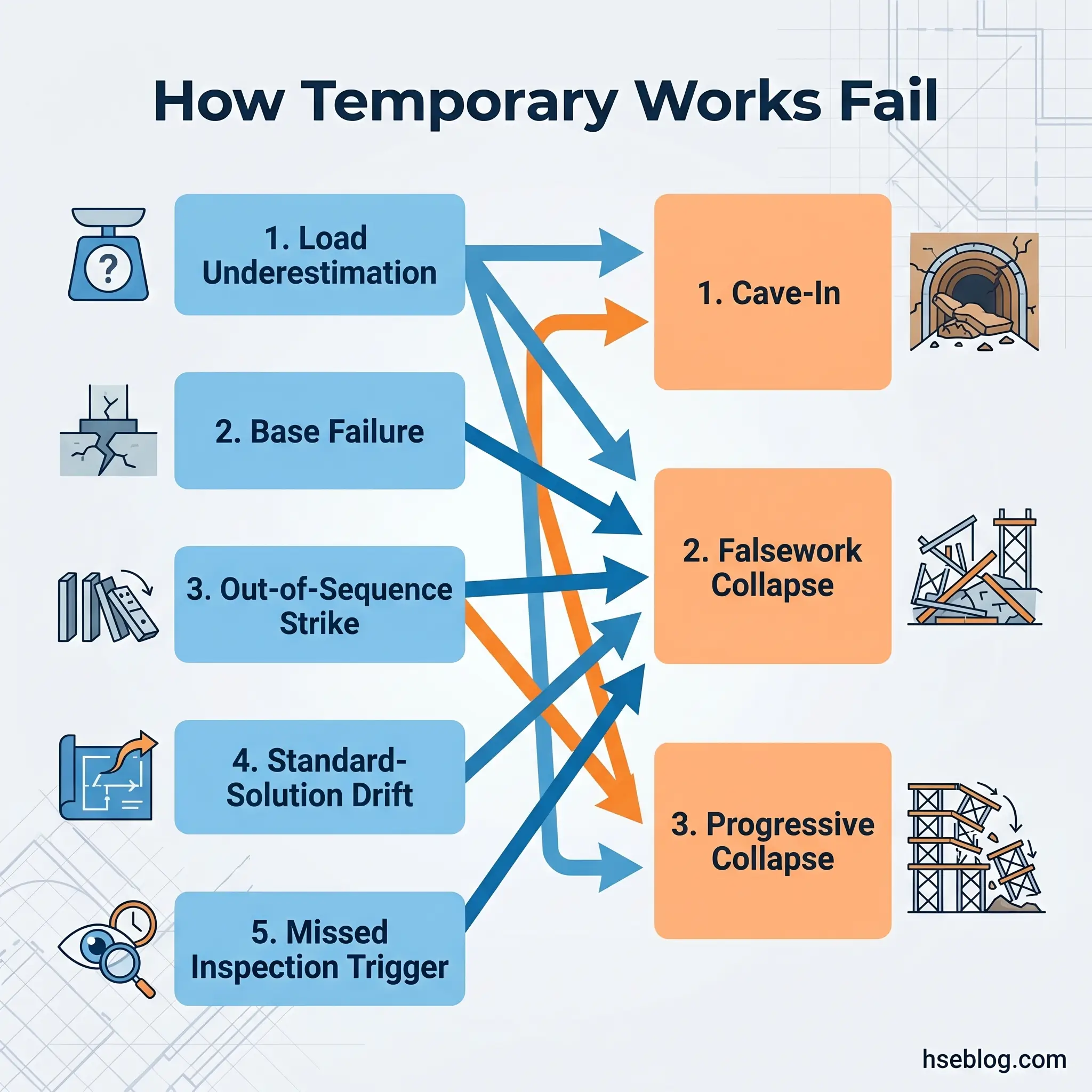
Progressive collapse is a distinct mechanism. When a single prop is struck out of sequence — or when a system was installed without a designed striking sequence — the remaining props may be unable to redistribute the load. A common pattern in published investigations: a “nuisance” prop near a work area is removed, the adjacent slab deflects, the deflection loads adjacent props beyond their rated capacity, and the collapse propagates outward in under a second.
Load underestimation sits upstream of all of these. HSE has repeatedly identified underestimation of loads — particularly lateral loads from fresh concrete, wind on open falsework, surcharge from stored materials, or plant working near the edge of an excavation — as a dominant cause of temporary-works failure. Base failure is its counterpart at the foundation end: props punching through mudsills into soft ground, sinking after rain, losing contact after vibration.
Utility strike during shore installation — driving a shore or stake into an unmarked service — is a separate and serious hazard that sits on top of the collapse hazards. Struck-by injuries during erection and dismantling, and falls from height when working at deck edges above propping, round out the residual-risk picture. None of these are exotic. They are the same hazards HSE’s SIM guidance and OSHA citation history have pointed to for decades.
Pre-Work Planning: Design, Design-Check, and the Temporary Works Register
The procedural control that most decisively prevents failure is also the one most often treated as paperwork: the design and design-check process. Under 29 CFR 1926.652(b), a protective system for an excavation can be based on tabulated data (Appendices C, D), on manufacturer’s tabulated data for a proprietary system, or on a design prepared by a Registered Professional Engineer. Beyond 20 ft (6.1 m), only the RPE route is available.
Under BS 5975-1:2024, every temporary-works scheme starts with a design brief — scope, loads, constraints, ground conditions, interfaces with permanent works — issued by the principal contractor to the temporary-works designer. The design is then checked according to one of three categories. CAT 1 is a restricted check for simple schemes: standard props, needling, straightforward formwork. CAT 2 is an independent check by someone outside the design team but within the same organisation — typical for larger falsework, shoring towers, and standard excavation support. CAT 3 is the highest-rigour check, performed by a separate organisation — mandatory for major falsework, basements, tunnels, façade retention, and any scheme involving novel or unusually complex load paths.
The Temporary Works Register is the procedural spine that holds this together. It is not a compliance spreadsheet. Under BS 5975-1:2024 it records design brief, designer, checker, check category, Permit to Load, Permit to Strike, inspection records, and dismantling sign-off. Every action has a named owner and a date. HSE treats it as a live control document because the register is how the TWC demonstrates the scheme has been followed in practice — not merely that it exists on a shared drive.
Soil Classification Under OSHA Appendix A — The Decision That Drives Everything Downstream
Soil classification is the single most consequential judgment call on a US trench job. Type A is cohesive soil with an unconfined compressive strength of 1.5 tsf or greater — stiff clay, for example. Type B is cohesive soil below 1.5 tsf or granular cohesionless soil — silt, sandy loam. Type C is the weakest — granular soils like sand and gravel, submerged soil, or soil from which water is freely seeping. Downgrading is mandatory when conditions warrant; upgrading to justify a steeper slope or lighter shoring is not.
A recurring pattern in OSHA citation history: a competent person classifies a mixed-profile trench as Type A based on the top two feet, when the bottom three feet is saturated granular material that must be classified Type C. Under Appendix A, once you have any Type C layer, the entire excavation must be treated as Type C — the weaker classification governs.
Safe Installation Procedures
Written procedures do not protect workers. Competent supervision, working from a clear scheme, does. That said, the sequence is teachable — and a disciplined installation sequence removes most of the common installation failures from the table.
Pre-installation begins with verification that the design matches site conditions. If the ground, the loads, or the geometry have changed since the design was produced, installation does not begin until the TWC or competent person confirms the scheme is still valid or issues a revised design. Materials are checked individually — no bent or corroded props, no mismatched components, no proprietary hardware substituted for pins.
Base preparation matters as much as the shores themselves. Props and shore feet bear on solid, level, load-bearing surfaces. Mudsills or engineered bearing plates spread the load; dirt, debris, asphalt, or unconsolidated fill do not qualify as bearing surfaces. Verticality is set with a spirit level after adjustment — a 1–2° lean can measurably reduce the axial capacity of a steel prop under EN 1065 classification. Pins go through adjustment holes; threaded adjustment on its own is not a pin-through connection, and any operator familiar with EN 1065 proprietary equipment should treat that rule as non-negotiable.
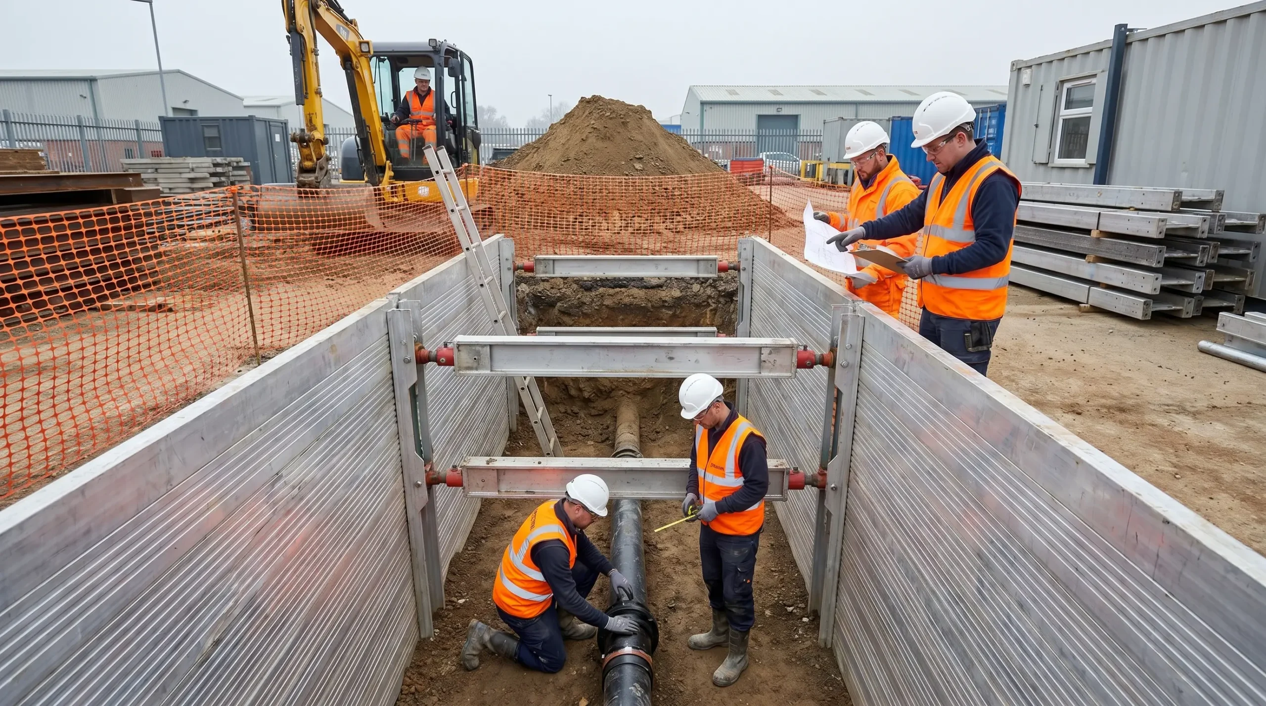
In trench work, shoring is installed as the trench is excavated, not after. Workers must not enter an unprotected trench to install shoring — the protective system is set from outside or from within a previously protected section. For trench props and façade retention, controlled preloading engages the soil or wall before any further movement can occur; preloading is a cave-in prevention principle, not a cosmetic step.
The Fix That Works: Before the first prop lands, walk the actual footprint with the design in hand. Check each prop location against the drawing. Confirm soil classification is current. Verify the bearing surface. Check the material against the component list. This walk takes 15 minutes on most jobs and prevents the two most common installation failures: wrong component in position, and prop bearing on unsuitable ground.
Mixed-manufacturer component stacks are a named failure mode in both OSHA and HSE safety alerts. Proprietary systems are designed, tested, and rated as complete systems. Substituting a scaffolding coupler for a shoring coupler, or a Class C steel prop for a Class D because it was closer to the store, is the installation-level equivalent of design-check avoidance.
Inspection, Monitoring, and the Competent Person’s Duties
The competent-person role is the load-bearing wall of the whole inspection framework, but the definitions are narrower than most crews assume. Under OSHA 1926.650, a competent person is one capable of identifying existing and predictable hazards AND authorised to take prompt corrective action. Both parts of that definition matter. Nominating a site supervisor as the competent person without giving them stop-work authority is not competent-person appointment — it is paperwork.
The practical reading of 1926.651(k) requires inspection by that competent person before each shift, after every rainstorm, and after any other occurrence that could increase hazards. A tour during lunch does not meet the requirement if workers have already been in the trench for four hours. In the UK, the TWC under BS 5975-1:2024 uses a hold-point model — the Permit to Load is effectively a formal inspection sign-off, layered over daily walk-throughs.
What to inspect is where most checklists go wrong by being generic. For propping and shoring specifically, the inspection points are:
- Prop verticality and pin engagement — every prop checked for lean after adjustment, every pin visible and locked through the adjustment hole
- Base bearing integrity — mudsills intact, bearing plates level, no signs of settlement or punching
- Adjacent member condition — cracking, deflection, or damage in nearby beams, walls, or slabs the scheme relies on
- Water accumulation — standing water in a trench, or saturation of the bearing ground under props
- Surcharge and setback — stored materials, spoil piles, and plant kept beyond the zone of influence specified in the design
- Soil condition changes — any change in the face of an excavation, any new seepage, any fresh tension cracks at the surface
Trigger-based re-inspection is the part competitor content most often misses. After rain, freeze-thaw, heavy plant movement, adjacent excavation, or any suspected impact, the pre-shift inspection is redone — not shortened. NPR’s 2024 analysis of US trench fatalities concluded that in most fatal cases, employers failed to follow basic federal regulations (NPR, 2024). The inspection framework exists; the gap is execution.
Safe Dismantling: Striking, Depropping, and Load-Transfer Control
Dismantling is the phase where the margin disappears. Installation is forgiving — if something is wrong, nobody is under it yet. Dismantling is the opposite: the structure, the workers, and the loads are all in position when the first support is released.
Sequence governs the work. The designer specifies the striking sequence — typically girders before beams before slabs on a formwork job, or mid-span outward on a long-span scheme. Site crews do not re-sequence. For formwork props, the striking sequence interacts with concrete strength: ACI 347 (US practice) and BS 8110 / Eurocode 2 (UK) require the concrete to have reached a specified minimum strength before props are removed. Verification uses maturity monitoring or field-cured cylinders — elapsed time from the pour is not an acceptable proxy, because curing temperature, mix design, and weather all shift the strength-gain curve.
Back-propping — or reshoring — is the bridge between early striking and full design strength. On a multi-storey concrete frame, reshores redistribute construction loads across two or three floors below the active pour. The reshore pattern is part of the formwork design, not a site decision. Removing reshores early, or on the wrong floor, can drive deflections into the permanent structure that cannot be corrected later.
The release itself is controlled. Steel props with preload or locked thread are released through the adjustable collar — never knocked out, never cut, never struck under live load. Before any removal, the team runs a pre-strike briefing, sets exclusion zones under and around the scheme, and restricts access to the dismantling sequence. After the strike, a final walk-down confirms the permanent structure is performing as intended before Permit to Strike is signed off in the Temporary Works Register.
Programme pressure is the environmental factor that creates most dismantling failures. The pour is ready, the formwork is needed on the next level, the prop-hire clock is running. A disciplined PM protects the designer’s sequence regardless — because a slab that deflects past its design limit because props came out two days early is a permanent defect the client will live with for the life of the structure.
Roles, Competence, and Training Requirements
The US framework names three roles: the Competent Person (1926.650–652), who inspects and holds stop-work authority; the Registered Professional Engineer, who designs protective systems beyond tabulated data or deeper than 20 ft; and the qualified supervisor with day-to-day charge of the work. Training routes into the competent-person role typically include the OSHA 30-Hour Construction course with the trenching module, competent-person trenching courses run by approved trainers, and manufacturer-specific training for any proprietary system on the job.
The UK framework under BS 5975-1:2024 and CDM 2015 adds procedural roles. The Temporary Works Coordinator manages the register, coordinates the design and check, issues the Permit to Load and Permit to Strike, and is the named duty-holder for temporary works across the site. On larger or multi-phase projects, one or more Temporary Works Supervisors work under the TWC. Training routes include the CITB Temporary Works Coordinator and Temporary Works Supervisor courses, NEBOSH and IOSH qualifications for broader HSE competence, and manufacturer-specific training for proprietary systems.
The legal point both jurisdictions share: nominating someone is not the same as ensuring competence. OSHA and HSE have both cited and prosecuted employers for appointing under-trained competent persons. A recurring issue in published UK prosecutions is the TWC role being bolted onto a site manager already holding three other responsibilities, with no real bandwidth to maintain the register or run hold-point inspections. That is not a staffing problem — it is a duty-holder problem.
Recurring Failure Modes and What They Reveal
The common thread across published temporary-works failures is that almost none of them involve unknown risks. HSE and OSHA have both stated publicly that temporary-works failures are overwhelmingly the result of known controls not being followed — and the same handful of failure modes appears in case after case.
The recurring patterns, each tied to the upstream control that should have prevented it:
- Load underestimation — lateral loads from wet concrete, wind, surcharge, or plant working near an excavation edge, not fully analysed in the design brief. Upstream control: complete design brief under BS 5975-1:2024 / RPE design under OSHA 1926.652.
- Standard-solution drift — a proprietary prop or trench box used without site-specific verification against actual soil, geometry, and loads. Upstream control: site-specific design check and TWC sign-off in the register.
- Misclassified soil — Type C conditions recorded as Type B or Type A to justify steeper slopes or lighter shoring. Upstream control: competent-person classification per OSHA Appendix A, with downgrading mandatory when any part of the profile warrants it.
- Mixed-manufacturer component stacks — scaffold couplers on shoring frames, non-matching pins, substituted hardware. Upstream control: proprietary-system integrity maintained, components checked against the design.
- Inspection-documentation lag — the register shows “inspected” but the physical scheme has drifted since the last walk-down. Upstream control: inspection entries based on actual walk-downs, not forward-dated sign-offs.
- Premature striking — formwork props struck before verified concrete strength, under programme pressure. Upstream control: strength verification by maturity or field-cured cylinders, not elapsed days.
- Trench box treated as trench shoring — workers assumed to be protected by a system that does not prevent a cave-in. Upstream control: protective-system selection per OSHA 1926.652 and Appendix F, with the competent person understanding the distinction.
Frequently Asked Questions
Conclusion
The safety procedures for propping and shoring do not fail because they are complicated. They fail because one step gets treated as optional — the design brief is rushed, the check is skipped, the register is filled in after the fact, the soil is upgraded to suit the preferred slope, the prop is struck on day 5 instead of day 9. Every recurring failure pattern in the published record maps back to a control that existed but was not executed.
So the real question is not whether your site has a temporary-works procedure on paper. It is whether a competent person — yours, not a nominal appointment — could walk the active propping and shoring on your job today, match every prop to a current design, confirm the bearing under every foot, pull up the last inspection entry against today’s weather and adjacent works, and sign the register with their own name. If that walk-down would surface three items that need closing before the next shift, the procedure is real. If the walk-down would surface thirty, the procedure is documentation, and the 12 US trench-collapse fatalities in 2024 are a statistic about other sites, not about yours — yet.