

TL;DR — Fire Hydrant Essentials
- A fire hydrant is a fixed water supply access point connected to a pressurized main, designed to deliver high-volume water flow to firefighters and fire suppression crews during emergencies.
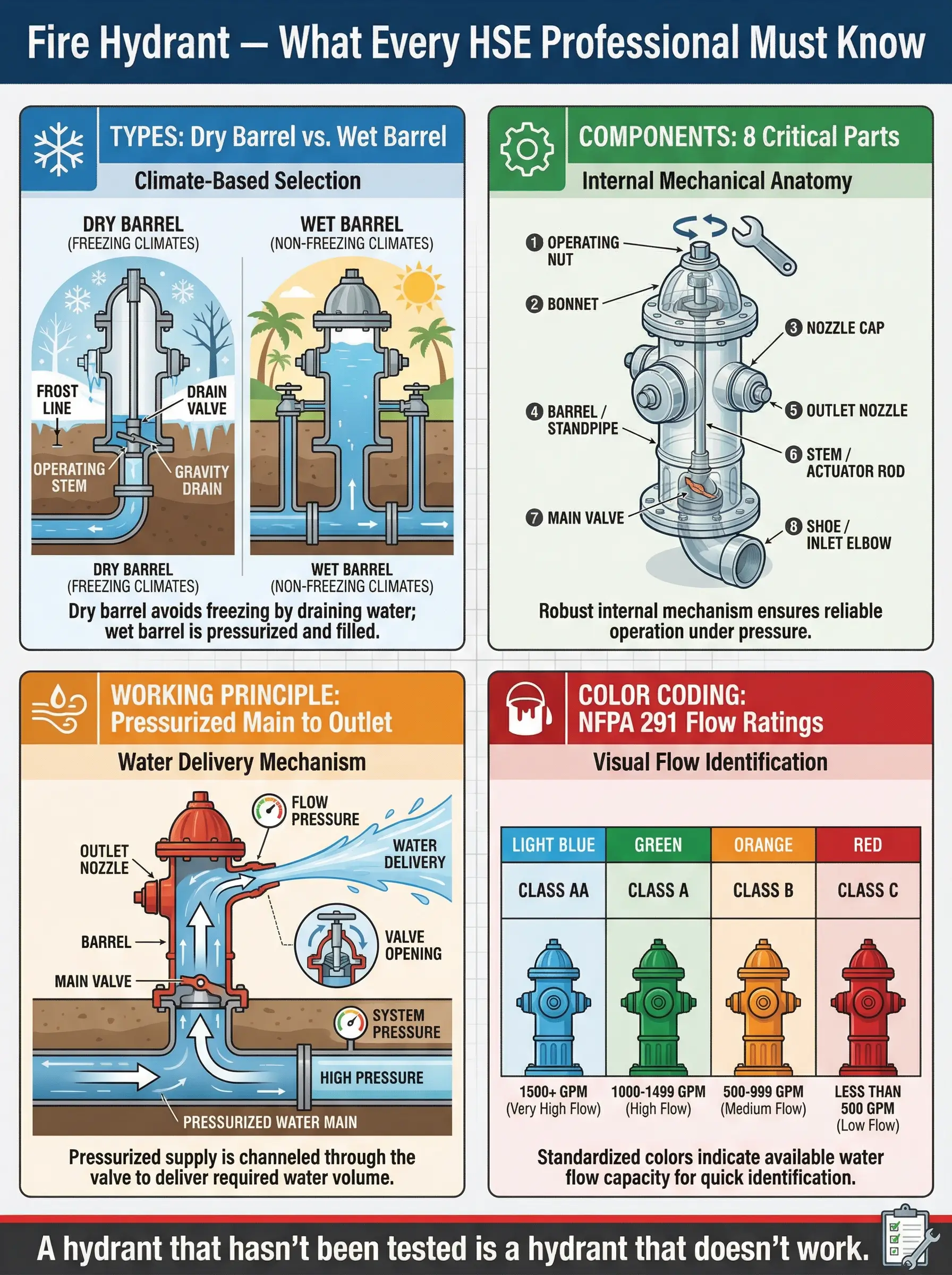
- Two primary types dominate global installations: dry barrel hydrants (used in freezing climates to prevent pipe bursts) and wet barrel hydrants (used in warm climates with constant water pressure to the outlet).
- Core components include the barrel, valve mechanism, outlet nozzles, bonnet, and underground supply connection — each one a potential failure point if maintenance is neglected.
- Color coding on hydrant bonnets and caps directly indicates available flow rate, following NFPA 291 guidelines — and misreading the color has caused critical delays on active firegrounds.
- Regular inspection, flow testing, and maintenance are non-negotiable — a hydrant that looks functional but hasn’t been tested can deliver zero water when lives depend on it.
I was on a refinery emergency response drill in the Gulf when the lead pump operator connected a 65mm hose to the nearest hydrant, opened the valve — and nothing came out. Not a trickle, not a sputter. Dead dry. Seventeen seconds of silence while a simulated tank fire scenario played out on the monitors behind us. That hydrant had been painted, inspected visually every quarter, and logged as “operational” in the asset register for three consecutive years. Nobody had ever opened it. The valve seat had corroded shut.
That moment reinforced something I carry to every site fire protection audit: a fire hydrant is not a street fixture or a background object in your emergency layout drawing. It is the single most critical water delivery interface between your fire suppression plan and the actual fire. When it fails, everything downstream — hose lines, monitors, foam systems, cooling sprays — fails with it. This article breaks down exactly what a fire hydrant is, how it works mechanically, the types used across different environments, the components that make or break its reliability, and the color coding system that tells first responders what flow capacity to expect before they even connect a coupling.
What Is a Fire Hydrant and Why Does It Matter in Fire Protection
A fire hydrant is a valve-controlled, above-ground connection point installed on a pressurized water supply main that allows firefighters and emergency responders to rapidly access large volumes of water for fire suppression. It serves as the interface between the underground water distribution network and portable or fixed fire suppression equipment — including hose lines, fire engine pumps, and monitor nozzles.
In practical terms, the fire hydrant converts buried infrastructure into usable fireground water. Without it, responders would need to draft water from open sources, rely entirely on tanker shuttles, or depend on limited onboard engine supplies. On industrial sites — refineries, chemical plants, power stations, logistics terminals — hydrants are part of the engineered fire protection system and are subject to design standards, spacing requirements, and flow rate calculations tied to the facility’s fire risk assessment.
The criticality of hydrants becomes visible only when they are needed. During a warehouse fire investigation I supported in Southeast Asia, the post-incident review found that three of five perimeter hydrants had been partially blocked by contractor material laydown areas. One had a missing operating nut. The fire crew lost over four minutes sourcing water from a hydrant 120 meters further away. The structure was a total loss. Four minutes. That is the margin a hydrant failure creates.
Key reasons fire hydrants are central to any fire protection strategy include the following:
- Immediate water access: A properly maintained hydrant delivers water within seconds of valve operation — no pumping delay, no drafting setup, no tanker wait time.
- High-volume flow capacity: Depending on the class, hydrants can deliver between 500 and 2,500 GPM (gallons per minute), which directly determines suppression capability for different fire sizes.
- Fixed infrastructure reliability: Unlike portable equipment, hydrants are permanently installed and mapped into pre-fire plans, giving responders a known, pre-positioned resource.
- Regulatory and insurance requirement: Standards such as NFPA 24, NFPA 25, and local fire codes mandate hydrant installation, spacing, and testing — non-compliance directly impacts facility operating permits and insurance coverage.
NFPA 25 (Standard for the Inspection, Testing, and Maintenance of Water-Based Fire Protection Systems) requires that fire hydrants be inspected annually and flow-tested at intervals not exceeding five years — with more frequent testing where local authority having jurisdiction (AHJ) requires it.
How a Fire Hydrant Works — The Operating Mechanism Explained
Understanding hydrant operation is not optional knowledge for HSE professionals responsible for fire protection systems. I have watched trained operators fumble with hydrant valves during emergency drills simply because nobody walked them through the mechanical sequence. The mechanism itself is straightforward — but every step matters.
The Basic Working Principle
A fire hydrant operates on a simple pressure-delivery model. The hydrant body connects to an underground water supply main that is kept under constant pressure by the municipal or facility water distribution system. When the hydrant valve is opened, that pressurized water flows upward through the barrel and out through the discharge outlets (nozzle caps), where hoses or pumping equipment are connected.
The sequence from standby to water delivery follows a clear mechanical chain:
- Operating nut engagement: A hydrant wrench is placed on the pentagonal operating nut located on the bonnet (top) of the hydrant. This nut connects to the stem that controls the main valve.
- Stem rotation: Turning the operating nut counterclockwise rotates the stem downward through the barrel. The number of full turns required varies by manufacturer — typically between 8 and 16 turns for a full open position.
- Main valve opening: The stem pushes the main valve (located at the base of the hydrant, below the frost line in dry barrel types) off its seat, allowing pressurized water from the supply main to enter the barrel.
- Water fills the barrel: In dry barrel hydrants, the barrel fills from the bottom up. In wet barrel hydrants, water is already present in the barrel under static pressure.
- Discharge through outlets: Water exits through whichever outlet nozzle caps have been removed and connected to hose couplings. Flow rate depends on main pressure, hydrant size, and the number of outlets opened simultaneously.
- Valve closure and drainage: When the operating nut is turned clockwise, the valve closes. In dry barrel hydrants, a drain port at the base opens automatically as the valve closes, allowing residual water to drain out of the barrel — preventing freeze damage.
Pro Tip: During every hydrant inspection I conduct, I count the number of turns to full open and compare it against the manufacturer’s specification. If a valve that should take 12 turns suddenly opens fully at 8, the stem threads or valve seat may be worn — and that hydrant is heading toward failure under pressure.
Dry Barrel vs. Wet Barrel — The Operational Difference
The mechanical distinction between these two types affects how water behaves inside the hydrant at rest and has direct implications for climate suitability and maintenance requirements.
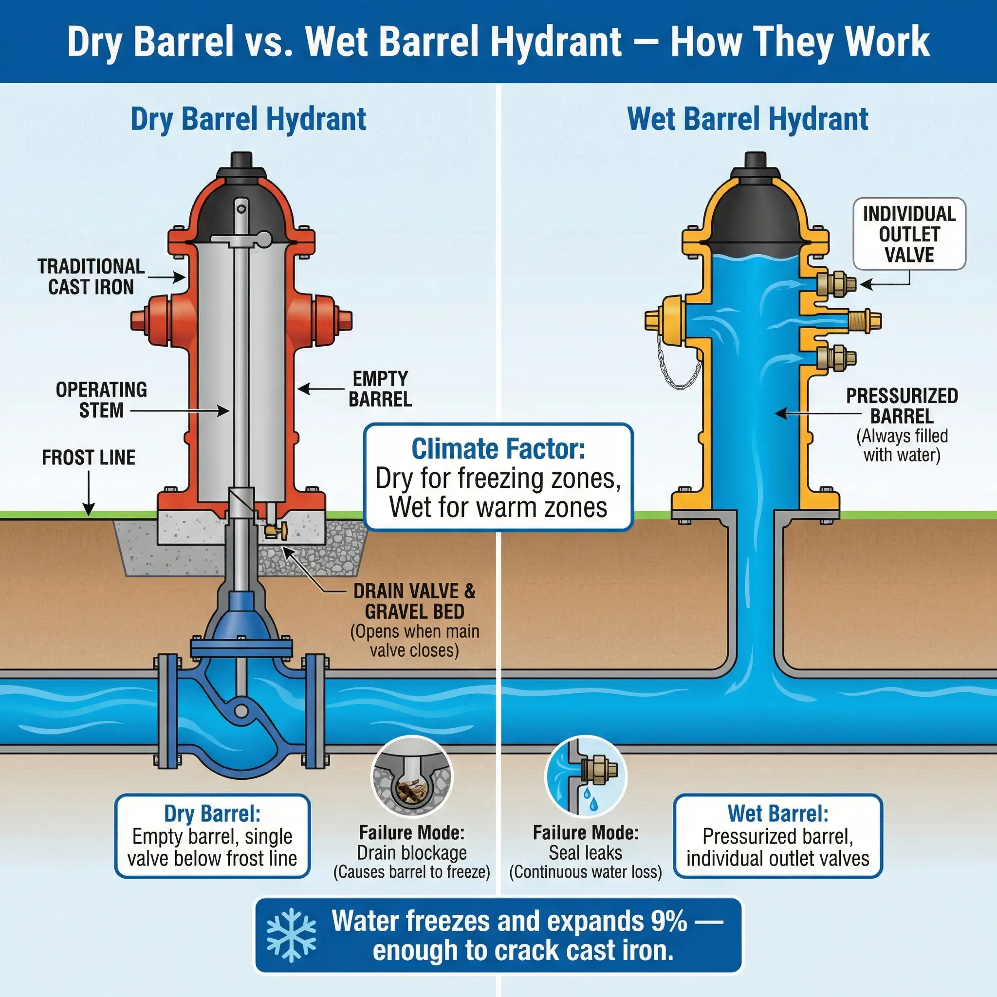
In a dry barrel hydrant, the main valve sits below ground level, below the frost line. When closed, the entire above-ground barrel is empty — hence “dry.” A drain valve at the base opens automatically when the main valve closes, draining residual water into a gravel sump or drainage system around the hydrant base. This prevents water from sitting in the barrel and freezing during cold weather, which would crack the barrel or block the outlets.
In a wet barrel hydrant, each outlet nozzle has its own individual valve. The barrel is permanently filled with pressurized water up to each outlet valve. Opening any individual outlet valve releases water immediately. There is no central main valve at the base. This design is simpler mechanically but is only viable in climates where freezing temperatures do not occur — because standing water in the barrel would freeze and rupture the casing.
| Feature | Dry Barrel Hydrant | Wet Barrel Hydrant |
|---|---|---|
| Water in barrel at rest | No — barrel is empty when valve is closed | Yes — barrel is always pressurized |
| Main valve location | Below ground, below frost line | No central valve; individual outlet valves |
| Freeze protection | Built-in drain valve prevents ice damage | None — not suitable for freezing climates |
| Climate suitability | Cold and temperate climates | Warm climates only (no frost risk) |
| Operation complexity | Single central valve via operating nut | Individual outlet valves opened separately |
| Common regions | Northern Europe, Northern US/Canada, high-altitude sites | Southern US, Middle East, tropical regions |
| Failure risk | Drain blockage causing barrel freeze; stem corrosion | Outlet valve leaks; seal degradation |
Types of Fire Hydrants — Classification by Design and Application
Beyond the dry barrel and wet barrel distinction, fire hydrants are classified by several additional criteria that determine where and how they are used. Selecting the wrong hydrant type for a given application is a design-phase error that cannot be corrected cheaply once the system is installed and commissioned.
Pillar Hydrants (Above-Ground)
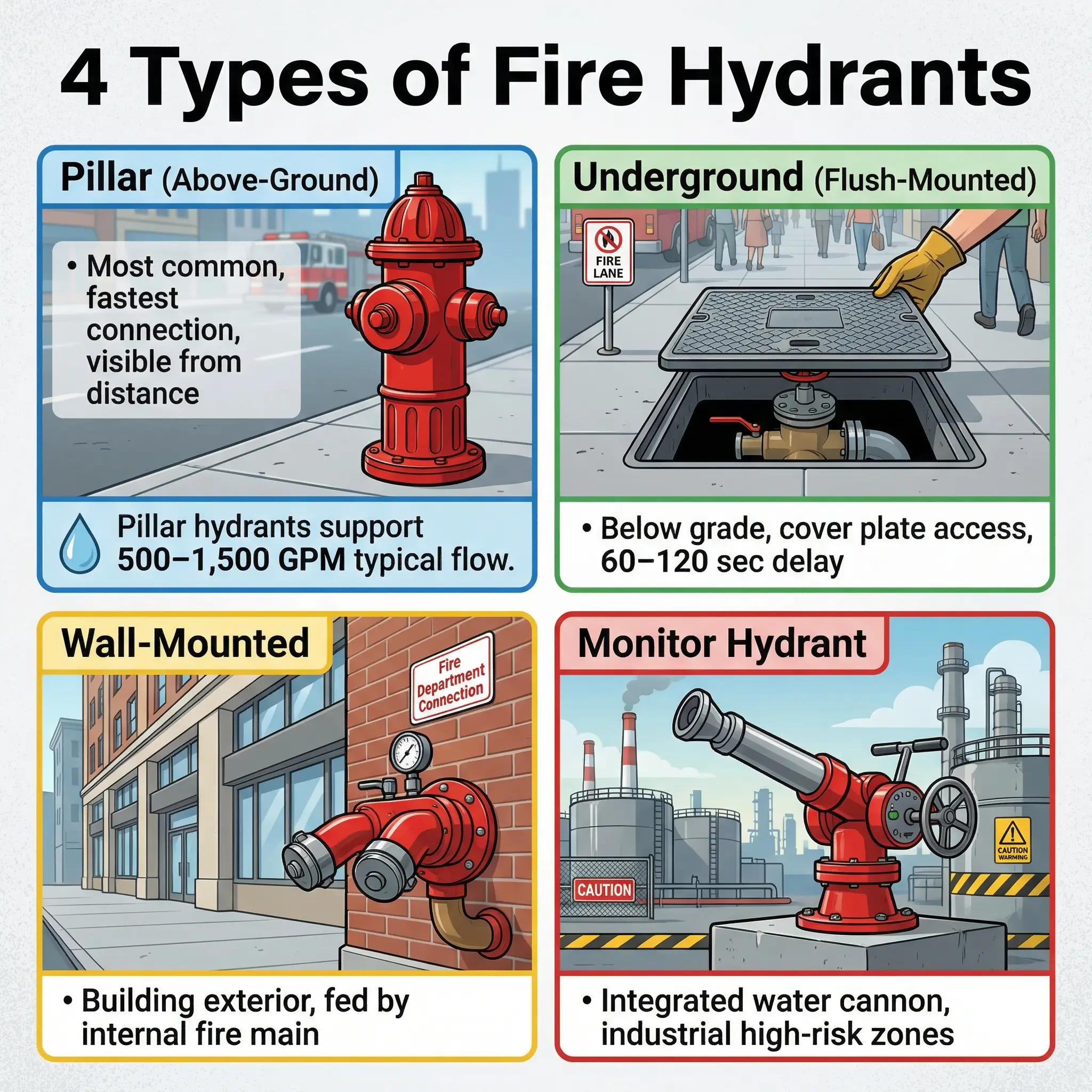
Pillar hydrants — also called post hydrants — are the most recognizable type. These are the above-ground, visible hydrant bodies that stand vertically on streets, along facility perimeters, and inside industrial complexes. They are designed for rapid visual identification and quick connection by fire crews.
Key characteristics of pillar hydrants include:
- Visibility: The above-ground barrel makes them easy to locate during emergencies, even in low-visibility conditions when painted in high-contrast colors.
- Multiple outlets: Most pillar hydrants have two 65mm (2.5-inch) hose outlets and one 100mm (4-inch) pumper outlet, though configurations vary by jurisdiction and standard.
- Flow capacity: Rated flow depends on the supply main size and pressure, but standard pillar hydrants typically support 500–1,500 GPM when connected to adequately sized mains.
- Maintenance access: All serviceable components — bonnet, operating nut, stem, nozzle caps, and outlet threads — are accessible above ground without excavation.
Underground Hydrants (Flush-Mounted)
Underground hydrants are installed below grade level with a surface-mounted cover plate or pit lid. They are common in locations where above-ground installations would obstruct traffic, pedestrian movement, or aesthetic requirements — particularly in European city centres, airport aprons, and heritage zones.
These hydrants present specific operational challenges that HSE teams must account for:
- Location marking: Because they are not visible above ground, underground hydrants must be marked with surface plates, indicator posts, or pavement markings. During an airport apron fire drill I observed in Northern Europe, the response crew spent 40 seconds locating the underground hydrant cover because the surface marker had been paved over during a runway resurfacing project.
- Access delay: Opening the cover, inserting the standpipe adapter, and connecting hose lines adds 60–120 seconds compared to a pillar hydrant — a significant delay on an active fireground.
- Debris and flooding risk: Pit-mounted hydrants accumulate dirt, gravel, standing water, and occasionally ice, all of which can obstruct operation or damage the valve mechanism.
Wall-Mounted Hydrants
Wall-mounted hydrants are installed on the external walls of buildings or structures, typically fed by the building’s internal fire main or a dedicated riser. They are common in multi-storey industrial buildings, parking structures, and commercial complexes where perimeter pillar hydrants cannot provide adequate coverage to interior fire zones.
Monitor Hydrants
Monitor hydrants combine a standard hydrant connection with a fixed or portable monitor (water cannon) mounted directly on the hydrant outlet. These are used in high-risk industrial areas — tank farms, LPG storage facilities, chemical loading racks — where unmanned or rapid-deployment water streams are needed for exposure protection or direct fire attack.
Pro Tip: On petrochemical sites, I always verify that monitor hydrants are positioned with adequate reach to cover the design fire scenario in the facility’s fire risk assessment. I have found monitors installed with beautiful precision — pointed directly at a blast wall that would block 80% of the water stream from reaching the actual risk. Position verification against the fire protection layout drawing is a five-minute check that prevents a catastrophic gap.
Key Components of a Fire Hydrant — Anatomy of Reliability
Every fire hydrant is an assembly of interdependent components. A failure in any single part can render the entire unit non-functional. I approach hydrant inspections the same way I approach any critical safety equipment audit — component by component, with a clear understanding of what each part does and how it fails.
The following components make up the standard fire hydrant assembly, and each one deserves specific inspection attention:
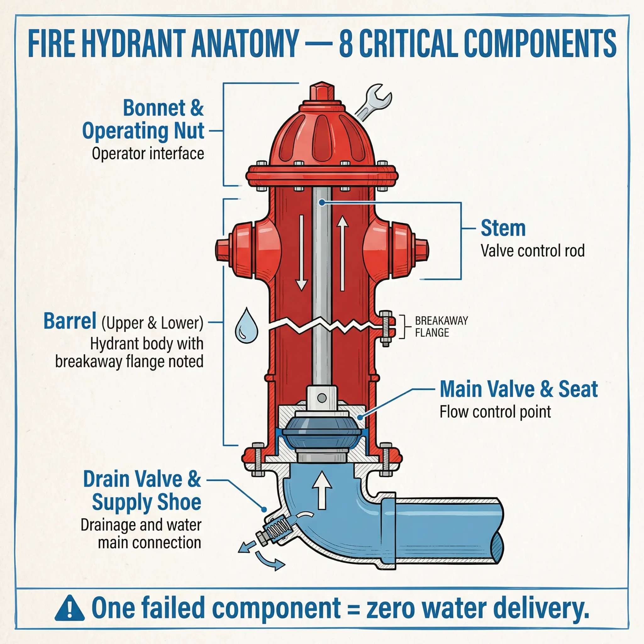
- Bonnet: The top cap assembly that houses the operating nut and seals the top of the barrel. The bonnet is typically bolted to the upper barrel flange. Corrosion, gasket failure, or cracked bonnets cause leaks under pressure and allow contamination into the barrel.
- Operating nut: The pentagonal (five-sided) nut on top of the bonnet that accepts a hydrant wrench. This is the operator’s interface with the valve. Damaged, rounded, or missing operating nuts are one of the most common field findings — and they make the hydrant inoperable without a specialty tool.
- Stem: The vertical rod that connects the operating nut to the main valve at the base. When the nut is turned, the stem rotates and moves the valve on or off its seat. Stem corrosion, bending, or thread wear causes the valve to stick, partially open, or fail to seal.
- Barrel (upper and lower): The vertical body of the hydrant. The upper barrel is the visible above-ground section. The lower barrel extends below grade to the valve and supply connection. In dry barrel hydrants, the barrel is designed with a breakaway flange — a weak point engineered to snap if the hydrant is struck by a vehicle, preventing the break from propagating below ground and causing an uncontrolled water release.
- Main valve and valve seat: Located at the base of the barrel in dry barrel hydrants, this is the gate or compression valve that controls water flow from the supply main into the barrel. The valve seat is the machined surface the valve presses against to create a watertight seal. Wear, corrosion, or debris on the seat causes the valve to leak or fail to close completely.
- Drain valve (dry barrel only): A small auxiliary valve at the base that opens automatically when the main valve closes. It allows residual water to drain from the barrel into the surrounding gravel sump. If the drain is blocked — by silt, debris, or ground settlement — water remains trapped in the barrel and freezes in cold weather, cracking the barrel from the inside.
- Outlet nozzles and caps: The threaded discharge ports on the barrel where hose couplings connect. Caps protect the outlet threads from damage, corrosion, and debris. Nozzle caps should have gaskets and operating chains. Missing caps or damaged threads delay connection and can cause coupling failure under pressure.
- Supply connection (shoe): The bottom elbow or tee fitting that connects the hydrant barrel to the underground water supply main. This connection is buried and is the most difficult component to inspect or repair without excavation.
NFPA 24 (Standard for the Installation of Private Fire Service Mains and Their Appurtenances) specifies installation, connection, and material requirements for hydrant assemblies, including valve type, barrel material, outlet configuration, and connection to the water supply main.
Fire Hydrant Color Coding — What the Colors Mean and Why They Matter
Color coding on fire hydrants is not decorative. It is a standardized visual communication system that tells arriving fire crews — in seconds, from a distance — what flow capacity to expect from that hydrant before they ever open a valve or connect a line. Misreading the color, or encountering a hydrant that has been painted incorrectly, can cause crews to underestimate or overestimate available water — both of which have direct tactical consequences on the fireground.
NFPA 291 Color Coding Standard
NFPA 291 (Recommended Practice for Fire Flow Testing and Marking of Hydrants) establishes the widely adopted color coding system used across North America and referenced internationally. The system uses two separate color signals on each hydrant.
The barrel (body) color indicates the water source type — which system is supplying the hydrant:
- Chrome yellow: Public water system hydrant (the standard municipal supply).
- Red: Private system hydrant (supplied by a facility’s own fire water system — tank, pump, or dedicated main).
- Violet/light purple: Non-potable water supply (reclaimed water, lake water, or other non-drinking-water source).
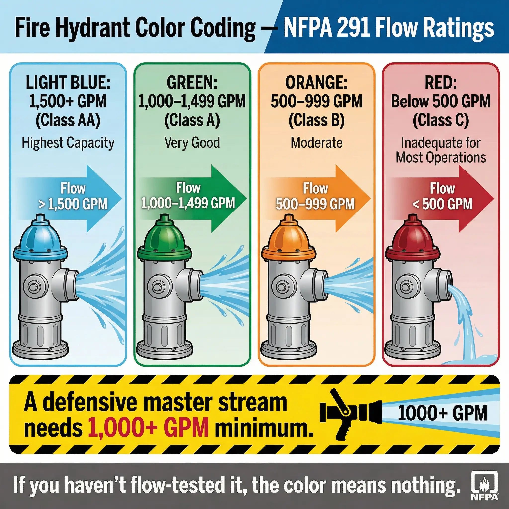
The bonnet and caps color indicates the available flow rate — the volume of water the hydrant can deliver based on flow testing. This is the tactically critical color for fire crews:
| Bonnet/Cap Color | Flow Rate (GPM) | Classification |
|---|---|---|
| Light blue | 1,500 GPM or greater | Class AA — Superior supply |
| Green | 1,000–1,499 GPM | Class A — Very good supply |
| Orange | 500–999 GPM | Class B — Moderate supply |
| Red | Below 500 GPM | Class C — Inadequate for most firefighting operations |
This classification directly impacts fireground decisions. A crew arriving at a working structure fire needs to know instantly whether the nearest hydrant can sustain two attack lines (requiring 500+ GPM) or a defensive master stream operation (requiring 1,000+ GPM). The bonnet color provides that answer at a glance.
Pro Tip: During a fire protection audit at a logistics terminal in North America, I found that maintenance crews had repainted all hydrants — barrel and bonnet — in a uniform bright red as part of a “facility beautification” project. Every flow-rate distinction was erased overnight. The fire crew mutual aid agreement with the local department depended on those color codes for pre-planning. It took three months and a full flow testing program to restore correct markings. Never let anyone paint a hydrant without referencing the flow test data and NFPA 291.
Why Color Coding Fails in the Field
Despite the clarity of the standard, color coding errors are alarmingly common. The following failures appear repeatedly in field audits:
- Uniform painting: Maintenance or facility teams paint all hydrants the same color for aesthetic consistency, destroying the flow-rate visual system entirely.
- Faded or peeling paint: UV exposure, weather, and industrial environments degrade paint within 2–3 years. A green bonnet fades to look like light blue — or worse, becomes unreadable.
- No flow testing basis: Hydrants are color-coded based on assumption or original design flow, not actual flow test results. Supply conditions change over time — new connections, main deterioration, pressure drops — and the color must reflect tested, current capacity.
- Non-NFPA jurisdictions: Many countries outside North America use different color systems or no standardized system at all. HSE professionals working internationally must verify which standard applies at each site and ensure fire crews are briefed accordingly.
Fire Hydrant Inspection, Testing, and Maintenance — Keeping the System Alive
A fire hydrant is only as reliable as its last inspection and test. Visual inspection confirms the hydrant is physically present and appears intact. Flow testing confirms it actually delivers water at the rated pressure and volume. Both are required. Neither alone is sufficient.
I have lost count of the number of “green tag” hydrants I have found on sites that passed visual inspection but failed operationally — seized valves, blocked drains, collapsed supply connections, nozzle threads corroded beyond coupling. The inspection program must include both visual and functional elements on a defined schedule.
Visual Inspection Checklist (Annual — Minimum)
The following items should be verified during every visual hydrant inspection round:
- Accessibility: Hydrant is unobstructed with a minimum 1-meter clear radius. No vehicles, material storage, vegetation, or construction debris blocking access or visibility.
- Physical condition: Barrel is upright, not leaning, no visible cracks, dents, or corrosion through the paint. Bonnet is secure with no loose bolts.
- Operating nut: Present, intact, pentagonal shape not rounded. Accepts a standard hydrant wrench without slipping.
- Outlet caps: All caps present, chained, with intact gaskets. Threads clean and undamaged. Caps removable by hand or with standard wrench.
- Color coding: Barrel and bonnet colors match the last flow test results per the applicable standard. Paint is legible and not faded beyond recognition.
- Ground condition: No standing water around the base (may indicate leaking drain valve or main connection). No subsidence or ground settlement that could stress the supply connection.
- Signage and marking: Hydrant location marker or indicator post visible. Fire lane or no-parking zone markings intact if applicable.
Flow Testing (Every 3–5 Years or Per AHJ Requirement)
Flow testing is the only way to verify actual hydrant performance. It measures static pressure, residual pressure under flow, and calculated available flow rate — the data that determines the correct bonnet color code.
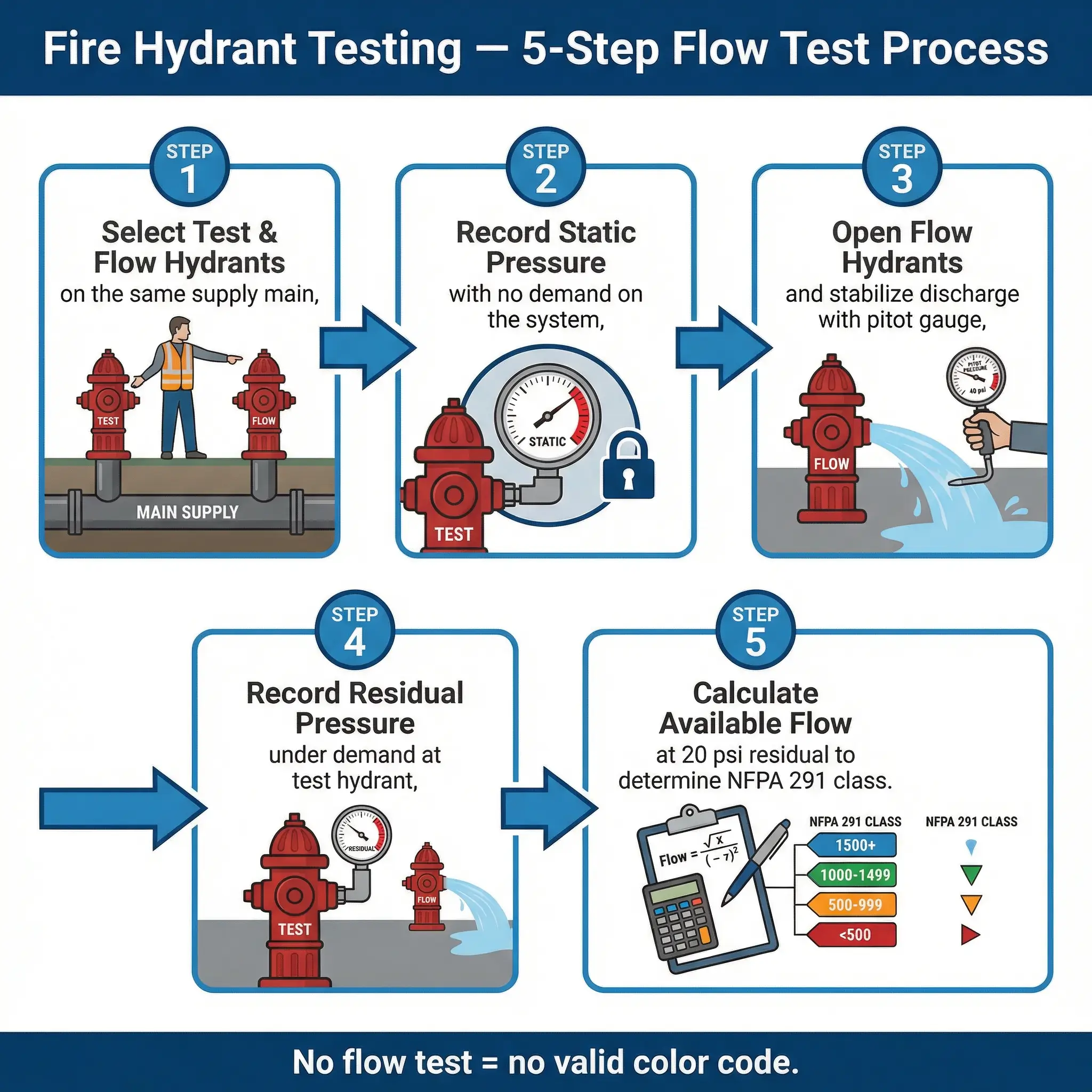
The standard flow test procedure follows this sequence:
- Select a test hydrant and one or more flow hydrants on the same main. The test hydrant measures pressure; the flow hydrant(s) discharge water to create demand.
- Record static pressure at the test hydrant with all flow hydrants closed. This is the baseline system pressure with no demand.
- Open the flow hydrant(s) fully and allow flow to stabilize. Measure the discharge using a pitot gauge at each open outlet.
- Record residual pressure at the test hydrant while the flow hydrant(s) are discharging. The pressure drop under demand indicates the system’s ability to sustain flow.
- Calculate available flow at a standard residual pressure (typically 20 psi) using the hydraulic formula. This calculated flow determines the NFPA 291 color classification.
- Flush the hydrant after testing to clear sediment and debris mobilized during the flow. Slow-close the valve to prevent water hammer.
Pro Tip: I always coordinate flow testing with the facility operations team and the water utility in advance. Unannounced flow testing on an active industrial site can drop system pressure enough to trigger low-pressure alarms on fire suppression systems, process cooling loops, and even potable water supply. One uncoordinated test at a food processing plant triggered a boil-water advisory for the adjacent residential area. Communicate before you test.
Common Field Mistakes That Compromise Fire Hydrant Reliability
Even well-designed and properly installed hydrant systems degrade when common operational and management errors go unchecked. These are not theoretical risks — they are findings I have documented across dozens of facility audits and post-incident reviews.
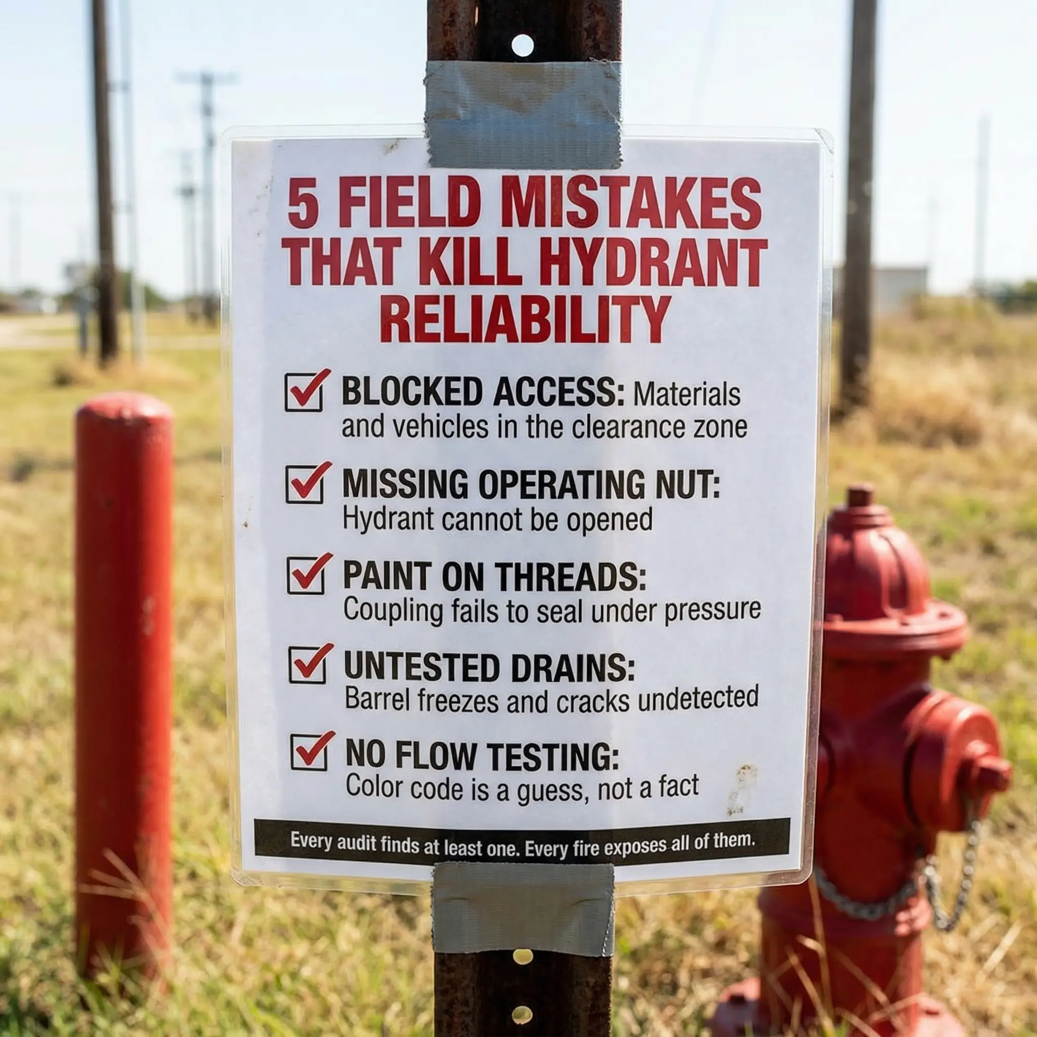
The most frequent and consequential mistakes include the following:
- Blocked access: Materials, vehicles, dumpsters, or temporary structures placed within the hydrant’s operational clearance zone. During an emergency, every second spent moving obstructions is a second of uncontrolled fire growth.
- Missing or damaged operating nuts: Without the operating nut, the hydrant requires a specialty adapter or cannot be opened at all. Vandalism, corrosion, and accidental damage are common causes.
- Painting over outlet threads: Repeated repainting without masking the nozzle threads builds up layers that prevent hose coupling engagement. I have seen couplings fail to seat because of paint buildup less than 1mm thick — enough to prevent the gasket from sealing.
- Ignoring drain function (dry barrel): If the drain valve is not verified during inspection, water trapped in the barrel freezes in winter. The first sign of failure is a cracked barrel discovered only when the hydrant is needed. By then, the water supply is gone.
- Relying solely on visual inspection: A hydrant can look perfect externally and be completely non-functional internally. Visual inspection without periodic operational testing creates a false sense of security.
- Incorrect color coding after system changes: Supply mains are modified, new connections are added, system pressure changes — but hydrant colors are never updated to reflect the new reality. The bonnet says Class A; the actual flow tests at Class C.
- No hydrant map or pre-fire plan integration: Hydrant locations are not marked on emergency response plans, fire pre-plans, or facility plot plans. Responding crews waste critical time locating hydrants that should be pre-identified.
Field principle: “If you haven’t opened it, you don’t know if it works. If you haven’t tested it, you don’t know what it delivers. If you haven’t mapped it, you can’t find it when it matters.”
Fire Hydrant Spacing, Placement, and Design Standards
Hydrant placement is an engineering decision driven by fire risk assessment, not architectural convenience. The spacing and positioning must ensure that every point within a facility or district can be reached by hose lines connected to at least one — preferably two — functional hydrants.
Key standards and principles governing hydrant placement include the following:
- NFPA 24 specifies installation requirements for private fire service mains, including hydrant spacing on industrial and commercial properties. Typical spacing ranges from 90 to 150 meters (300–500 feet) depending on occupancy risk and fire flow demand.
- NFPA 1 (Fire Code) and local building codes specify minimum hydrant distribution for municipal systems, often requiring a hydrant within 120 meters (400 feet) of every building entrance, measured by hose lay distance — not straight-line distance.
- IFC/World Bank EHS Guidelines for industrial facilities recommend hydrant placement based on the facility fire hazard analysis, with hydrants positioned to cover all major risk areas including process units, storage zones, loading/unloading areas, and utility buildings.
- Accessibility requirement: Hydrants must be accessible to fire apparatus at all times. Permanent access roads with minimum turning radius and load-bearing capacity for fire trucks must be maintained. Seasonal conditions — snow accumulation, mud, flooding — must be accounted for in placement decisions.
- Elevation and terrain: Hydrants installed at elevations significantly above the supply main will experience reduced static pressure. Hydraulic calculations must account for elevation loss (approximately 0.43 psi per foot of elevation) to ensure adequate delivery pressure at the hydrant outlet.
Conclusion
A fire hydrant is one of the simplest devices in any fire protection system — a valve, a barrel, and a connection to pressurized water. There is no software, no sensor, no automation. And yet it remains one of the most neglected pieces of life-safety infrastructure on industrial sites and in municipal systems alike. The failures I have documented over the years are never dramatic engineering breakdowns. They are quiet, predictable decay — a seized valve, a blocked drain, a painted-over thread, an untested flow rate printed on a faded bonnet.
The professionals who prevent hydrant failures are not doing complex work. They are doing consistent work. They open the valve annually. They flow-test on schedule. They verify the color code against actual data. They keep the access zone clear and the operating nut intact. They put the hydrant on the plot plan and brief the emergency response team on its location, capacity, and condition. None of this is difficult. All of it requires discipline.
Every hydrant on your site represents a promise — that when fire occurs, water will be available, at adequate pressure, in adequate volume, within seconds. If you have not personally verified that promise through physical inspection and flow testing, then it is not a promise. It is an assumption. And assumptions do not extinguish fires.