

TL;DR
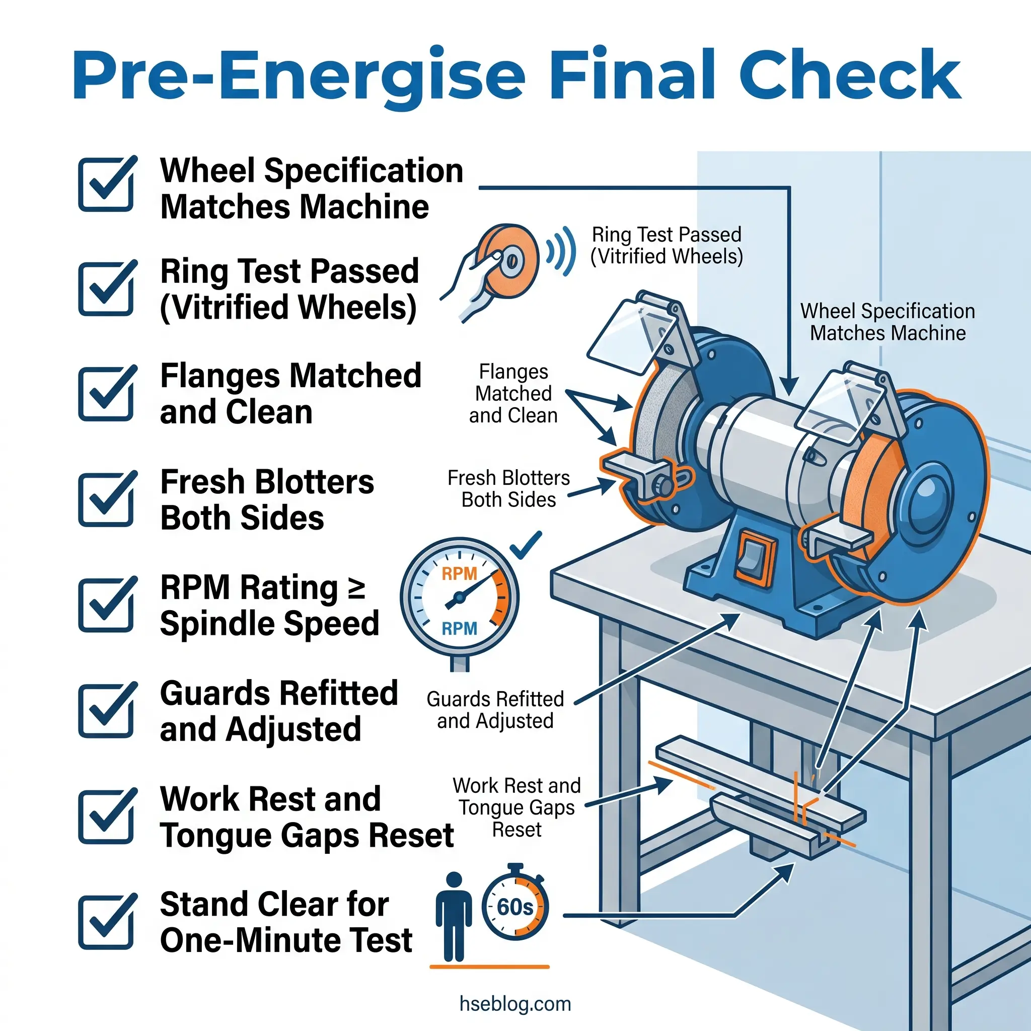
- Inspect every wheel before mounting. Visual check for cracks, chips, and moisture damage; ring test for vitrified bonded wheels per OSHA 1910.215(d)(1) (US).
- Verify RPM compatibility before energising. The wheel’s maximum rated speed must equal or exceed the machine’s no-load spindle speed. Marginal overspeed causes delayed bond failure.
- Use matched flanges and a fresh blotter. Never reuse blotters, never mix flange sizes, and never force a wheel onto an undersized spindle.
- Run the new wheel for one minute in a protected area before grinding, with all personnel clear of the plane of rotation.
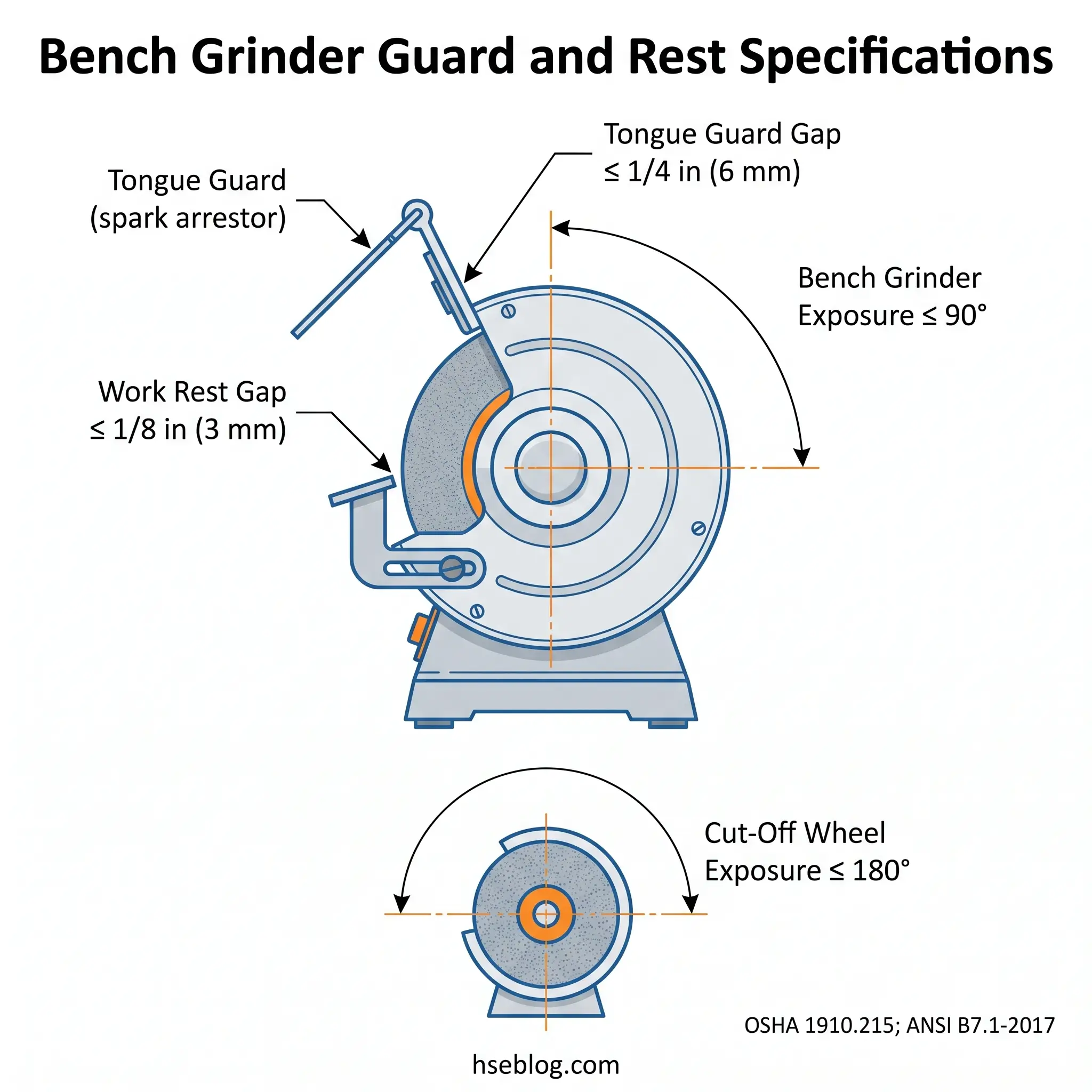
- Re-set work rest (≤1/8 in / 3 mm) and tongue guard (≤1/4 in / 6 mm) after every wheel change on bench grinders — OSHA 1910.215(a)(4).
Abrasive wheel mounting and inspection is a mandatory safety procedure performed immediately before fitting any abrasive wheel to a grinding machine. It involves visual inspection for damage, a ring test to detect hidden cracks in vitrified bonded wheels, verification that the wheel’s maximum RPM meets or exceeds the machine’s spindle speed, and correct assembly of flanges, blotters, and guards.
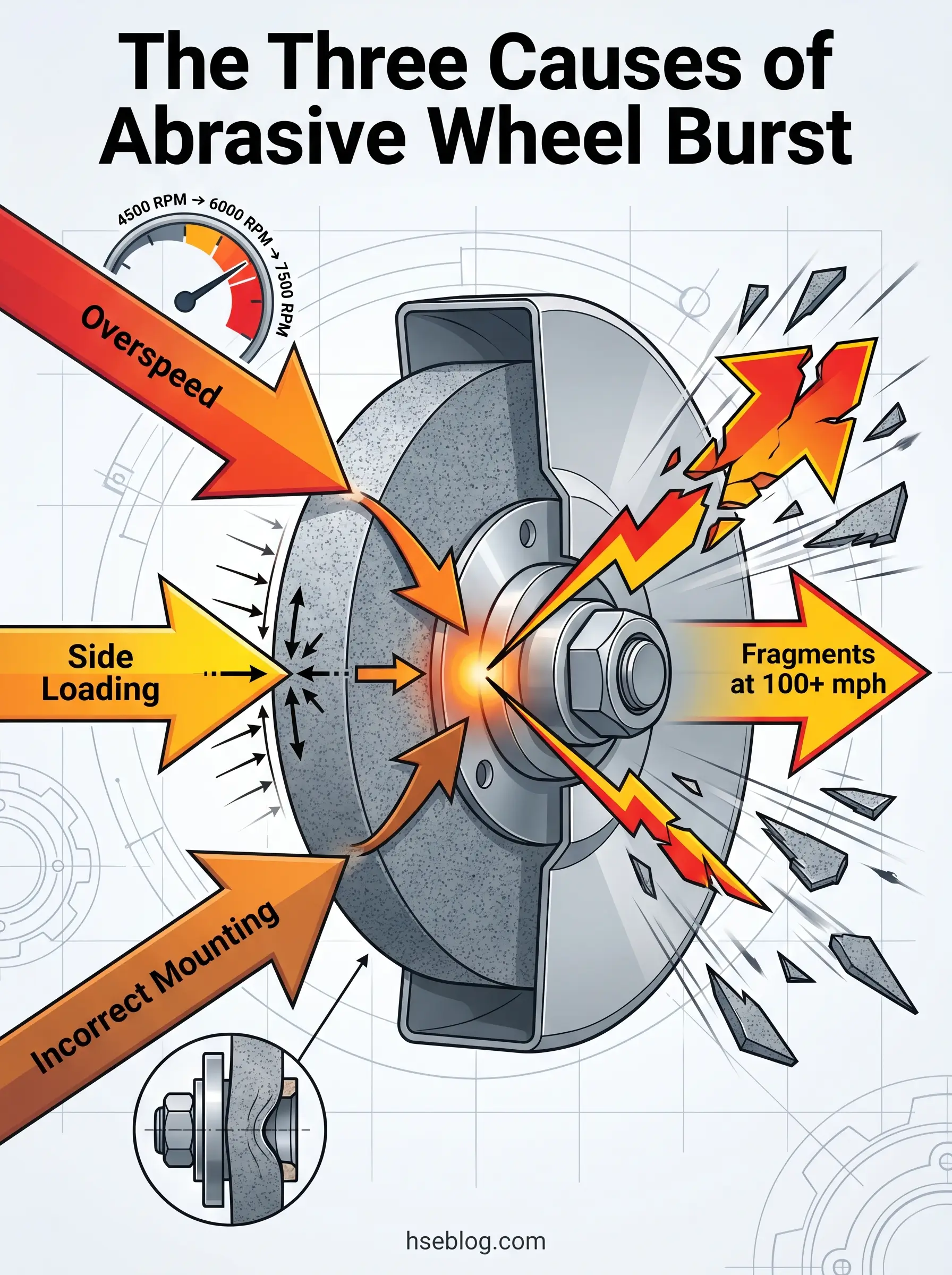
The vitrified bond holding the abrasive grains in a grinding wheel is, in practical terms, a network of glass. It is fired in industrial kilns above 1,200 °C and is engineered to keep tens of thousands of aluminium oxide or silicon carbide grains together while the wheel spins at peripheral speeds approaching 80 metres per second. At the rim of a 9-inch wheel running at 7,700 RPM, that is roughly 180 mph. At those speeds, a hairline crack invisible to the eye becomes a stress concentration that can split the wheel mid-cut. Fragments do not fall to the floor — they leave the housing at near-tangential velocity and travel through whatever stands in their path.
Abrasive wheel work rarely sits at the top of the high-risk task list at site induction, and that is the problem. Teams treat a wheel change as a quick swap — three minutes of inconvenience between cuts — and the published incident record reflects it. The Health and Safety Executive reports over 5,000 accidents each year linked to angle grinders alone in the UK (HSE, cited via CPDOnline, 2025), and nearly half of all abrasive wheel accidents trace back to unsafe systems of work or operator error (HSE HSG17, 2000). This guide walks through the abrasive wheel mounting and inspection procedure as it is actually carried out — visual inspection, ring test, speed verification, flange and guard work, the one-minute test run — with the regulatory framework set out alongside, so a mounter in the US, the UK, or the EU can read once and act correctly.
Why Abrasive Wheel Mounting and Inspection Is a Life-Critical Procedure
This article provides general HSE knowledge. Life-critical work such as mounting abrasive wheels must be planned and supervised by a competent person with relevant training, jurisdiction-specific authorisation, and machine-specific risk assessment. The information here does not replace that.
The mechanics are unforgiving. The bond — vitrified, resinoid, rubber, or shellac — has a finite tensile strength, and once centrifugal stress exceeds it, the wheel does not slow, deform, or warn. It separates. Fragments from a wheel rotating at 35 metres per second leave the rim at approximately 85 mph (126 km/h) (HSE, cited via CPDOnline, 2025); larger industrial wheels regularly exceed that.
Three failure modes dominate the published incident record: overspeed (running a wheel above its rated RPM), side loading (using the flat face of a Type 27 wheel for cutting, or wedging a cup wheel into a fillet), and incorrect mounting — missing or wrong-size flanges, a reused blotter, an over-tightened nut, or a wheel that passed visual inspection but failed an inadequate ring test. This article is principally about the third.
The pattern across investigation reports is consistent: the people involved were rarely reckless. They were rushed, undertrained for the specific task, or following a workplace habit that had drifted from the written procedure. An OSHA review of 27 grinder accidents over an eight-year span found that more than 26 percent resulted in employee deaths (according to an OSHA review cited by NKyTribune, 2025) — a fatality proportion that is uncommon among general industry hazards.
Who Is Authorised to Mount Abrasive Wheels?
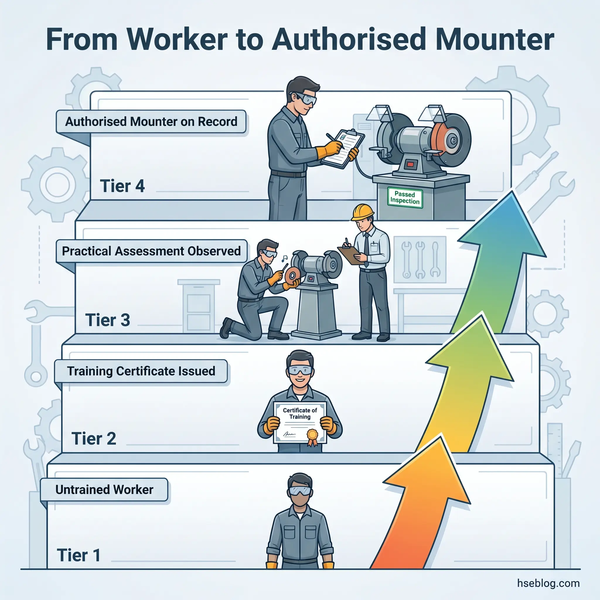
Two distinct competencies sit inside this procedure, and most workplaces conflate them. The mounter fits the new wheel — selecting it, performing the ring test, assembling flanges and blotter, adjusting guards, and running the test spin. The user picks up the grinder afterwards and operates it. Pre-use visual inspection is the user’s responsibility; pre-mounting inspection and the ring test are the mounter’s.
In the UK, PUWER 1998 requires employers to ensure that anyone using or supervising abrasive wheels has received adequate training, and HSG17 sets the practical benchmark for what that training covers — including selection, mounting, dressing, and safe use (HSE, HSG17, 2000). In the US, OSHA 29 CFR 1910.215(d)(1) places the inspection duty on the user immediately before mounting but does not formally designate a competent person for the mounter role; ANSI B7.1-2017 recommends a trained mounter, and most well-run facilities operate to that recommendation regardless of regulatory minimum. In the EU, EN 12413:2019 governs the products rather than the mounter, with national implementing regulations (such as the German BetrSichV) requiring demonstrable competence.
The recurring audit finding in every jurisdiction is the same: a stack of training certificates on file with no record of practical assessment. A certificate of attendance shows someone sat through a course; it does not demonstrate they can ring-test a wheel, identify a damaged flange, or set a tongue guard to the correct gap. Training providers issue the certificate; the employer remains responsible for assessing and recording observed competence (HSE / CPDOnline, 2025). A signed competence record from a supervisor who has watched the mounter perform the full procedure carries more weight than the certificate behind it.
| Jurisdiction | Governing reference | Who may mount | Competence evidence required |
|---|---|---|---|
| US (OSHA / ANSI) | 29 CFR 1910.215(d)(1); ANSI B7.1-2017 | User performs pre-mount inspection; ANSI recommends trained mounter | Training records; no formal competent-person designation in 1910.215 |
| UK (HSE) | PUWER 1998; HSG17 | Trained, employer-assessed person only | Training + documented practical assessment |
| EU (CEN) | EN 12413:2019 (product); national OSH law (mounter) | National requirement — typically trained personnel | Varies by member state; documented training is the minimum |
| Canada | CCOHS guidance; provincial OHS Acts | Trained workers; provincial requirements vary | Provincial OHS records |
| Australia | Safe Work Australia model WHS Regulations | Workers with documented training and supervision | Training records under WHS Act |
Pre-Mounting Inspection: Visual and Physical Checks
OSHA 29 CFR 1910.215(d)(1) is direct: immediately before mounting, all wheels shall be closely inspected and sounded by the user (ring-tested where applicable) to make sure they have not been damaged in transit, storage, or otherwise. The same obligation runs through ANSI B7.1, HSG17, and EN 12413. The reason it is written as “immediately before mounting” — not “during stock receipt” or “at quarterly audit” — is that wheels are vulnerable in storage. A stockroom inspection in March tells you nothing about whether the wheel got dropped against a steel rack in July.
Before any wheel goes onto a spindle, walk through the following:
- Specification match. Wheel type (1, 27, 41, etc.), bore, outer diameter, thickness, maximum permitted RPM, bond type, and grit must match what the machine and the work require. The wheel label and the machine nameplate should both be legible and consulted, not assumed.
- Visible damage. Cracks (often radiating from the bore), chips on the rim or face, gouges, glazing, oil contamination, and discolouration suggesting heat damage. A wheel with a chipped rim is condemned, not “used up.”
- Moisture and storage condition. Wheels stored leaning against walls, stacked without separators, or kept in unheated containers can absorb moisture into the bond. The “it was fine when we received it” defence does not survive the first ring test.
- Expiry date (resinoid wheels for handheld machines). Under EN 12413:2019, resinoid-bonded wheels for handheld machines must carry an expiry date, typically within three years of manufacture (oSa product marking guidance, 2019). The bond degrades over time; an expired cutting disc is a hazard waiting for a workpiece.
- Blotter condition. The paper or composite blotter on the wheel face must be intact and clean. A torn, oil-soaked, or missing blotter changes contact mechanics with the flange and produces uneven clamping stress.
The pattern that catches mounters out is moisture. A vitrified wheel that has spent six months in an unheated outbuilding can pass a visual inspection — the surface looks fine, the label is legible, the rim is undamaged — and still produce a dull thud when sounded. The bond has absorbed enough humidity to deaden the ring. That wheel is not safe to mount, no matter how good it looks.
How to Perform the Ring Test on an Abrasive Wheel
The ring test is the single most misunderstood element of this entire procedure. It is widely documented, frequently referenced in regulation, and routinely performed wrong — either on the wrong type of wheel, in the wrong conditions, or with the tap delivered as if the goal were to break the wheel.
The test exists because cracks inside the bond change the wheel’s vibrational behaviour. A sound wheel rings; a cracked one thuds. It works only when the wheel can vibrate freely and the bond is one that produces a clear tone. That means vitrified and silicate bonded wheels only. Organic-bonded wheels — resinoid, rubber, shellac — do not emit the same clear metallic ring as vitrified and silicate wheels (OSHA, 29 CFR 1910.215(d)(1)). For those, visual inspection is the primary defence and any structural test follows the manufacturer’s instructions.
For a vitrified wheel, the procedure is straightforward and should be conducted in this order:
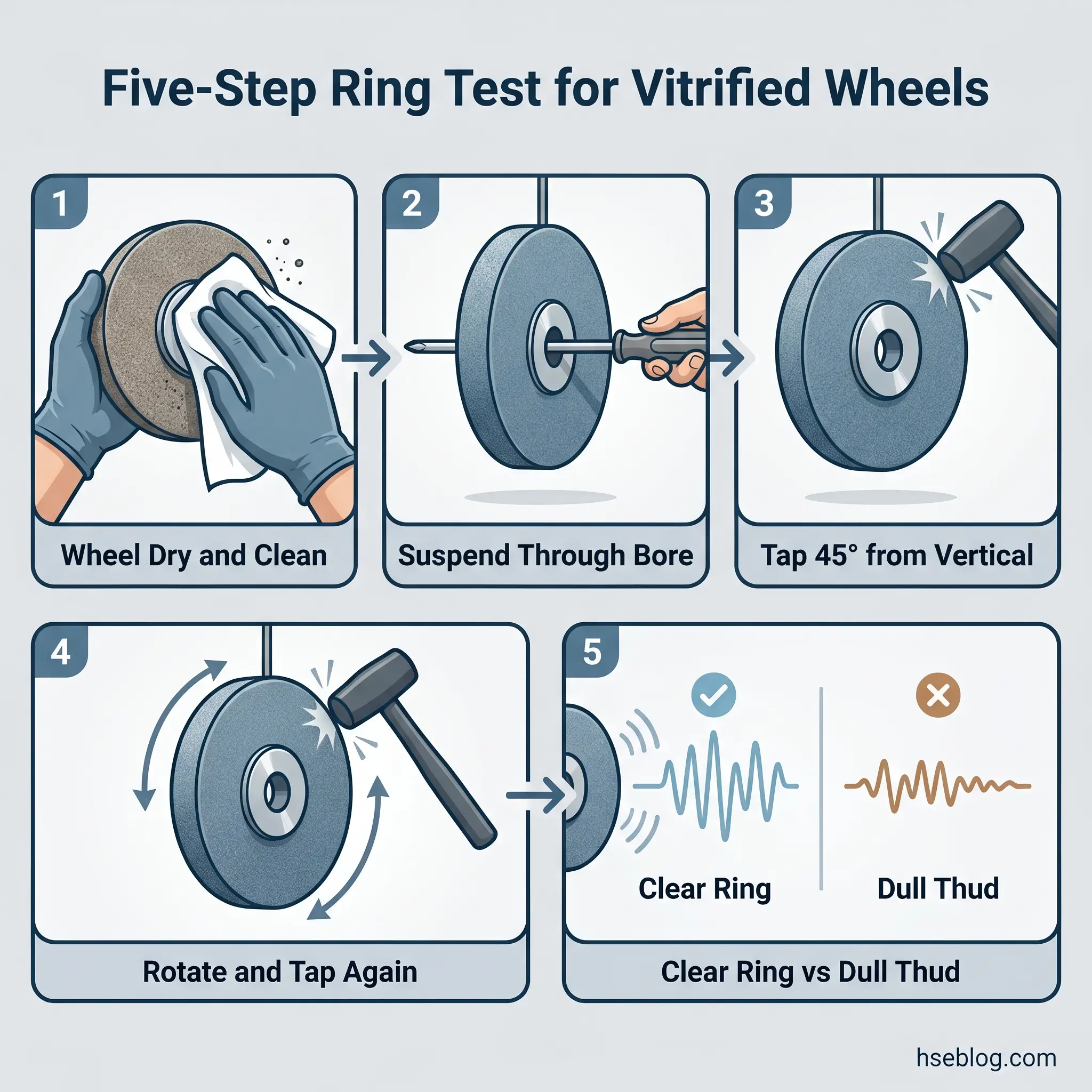
- Confirm the wheel is dry and free of dust, oil, swarf, and coolant. A damp or contaminated wheel will produce a dull tone regardless of internal condition (Norton Abrasives, ring test guidance).
- Suspend the wheel. Hold it through the bore on a screwdriver shaft, suspend it from a peg, or — for larger wheels — stand it on edge on a clean, hard surface. The wheel must not be gripped or muffled at the rim.
- Tap the wheel gently with a light non-metallic implement — the handle of a screwdriver works for smaller wheels; a wooden mallet handle for heavier ones. Tap at a point about 45° each side of the vertical centreline, 1 to 2 inches (25–50 mm) from the periphery (CDC/NIOSH abrasive wheel checklist).
- Rotate the wheel 45° and repeat. This ensures any directional crack is intercepted by at least one tap.
- Listen for a clear, metallic ring. A sound vitrified wheel rings like a small bell. A cracked wheel produces a dull, deadened thud. There is rarely ambiguity once a mounter has heard both.
Where new mounters struggle is calibration. The “clear ring” only sounds clear once the ear has heard a few of them. The honest practitioner habit is to tap a known-good wheel of the same specification first, then tap the wheel under test — direct comparison is far more reliable than memory. New mounters should perform their first ring tests under supervision of an experienced colleague until that ear is calibrated, and that supervision should be documented as part of the practical competence assessment.
When the Ring Test Does Not Apply
The ring test is not a universal pre-mount check, and applying it where it does not belong gives a false sense of security. Skip it — and rely on visual inspection plus manufacturer guidance — for the following:
- Resinoid, rubber, and shellac-bonded wheels. The bond damps the ring; the test cannot discriminate between sound and cracked wheels.
- Wheels under approximately 4 inches (100 mm) diameter and small mounted points. They do not produce a usable tone.
- Diamond and CBN (superabrasive) wheels with steel or resin bodies. The body and core construction make the test unreliable; follow the manufacturer’s specified inspection method.
- Cutting-off wheels — thin reinforced resinoid discs. Visual inspection of the face, rim, and reinforcing mesh, plus the EN 12413 expiry date, is the relevant check.
Step-by-Step Abrasive Wheel Mounting Procedure
Once the wheel has passed inspection, the mounting sequence itself is the next failure window. The procedure that follows is built for bench, pedestal, and portable grinders in general industry; precision and surface grinding machines have additional balancing and dressing steps that go beyond the scope of this article.
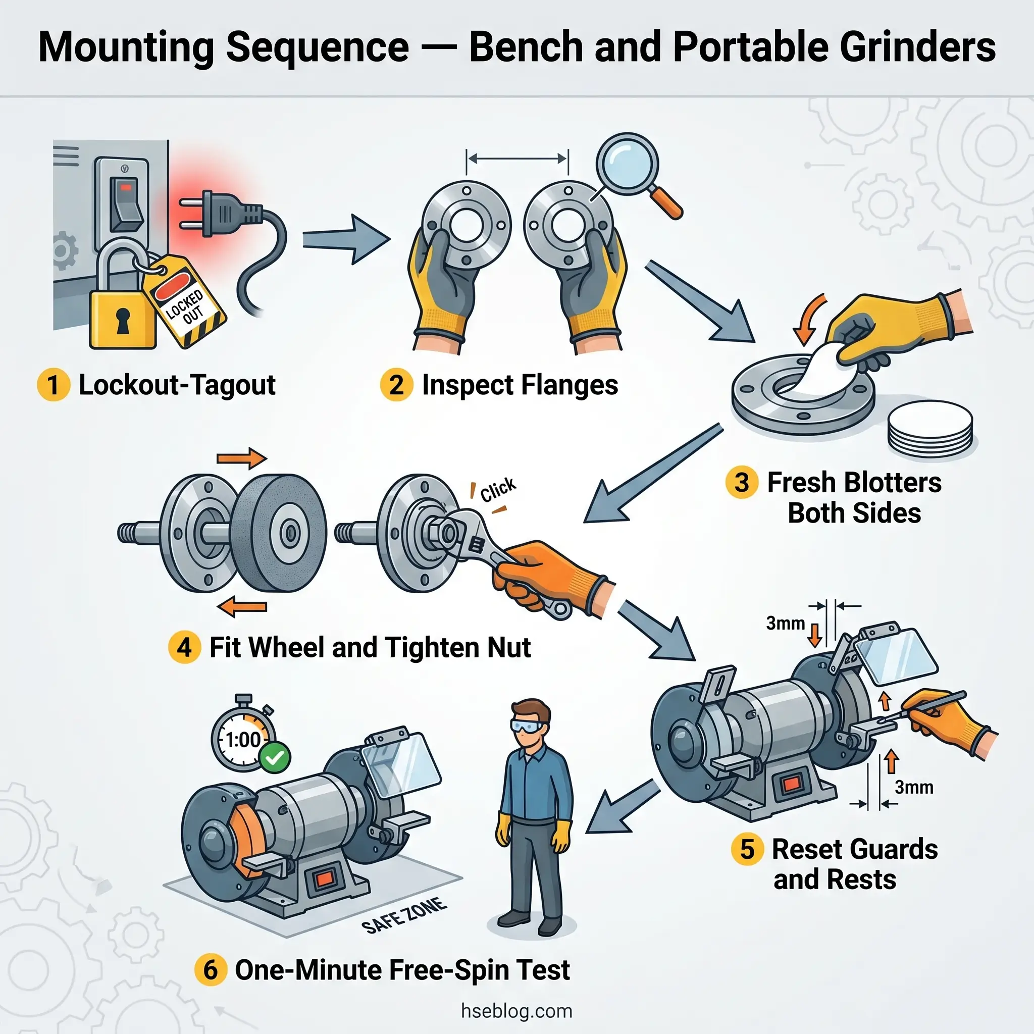
- Isolate the machine. Apply lockout-tagout before opening the guard or releasing the spindle nut. The grinder being “switched off at the wall” is not isolation. A mounter has been killed by a colleague hitting a start button on the other side of a workshop more than once in the published record.
- Inspect the flanges. Both flanges (back and front) must match in diameter, must be undamaged, and must be clean. Mismatched, dirty, or burred flanges concentrate clamping stress at one point on the wheel and crack it (Norton Abrasives mounting guidance). Undersized flanges are a particularly common audit finding on portable grinders that have been “modified” to fit oversized wheels.
- Fit a fresh blotter on each side of the wheel. Blotters distribute the clamping force evenly across the wheel face. They are not reusable — once compressed, they no longer deform consistently (CCOHS abrasive wheel guidance).
- Mount the wheel onto the spindle. The wheel must slide on freely. The machine spindle should be made to nominal size plus zero, minus 0.002 inch, with the wheel hole made suitably oversize to allow free fit (UAMA / ANSI B7.1; UpCodes referenced text). If a wheel will not go on without force, stop. Never enlarge the bore by drilling or tapping; never force-fit a wheel onto a worn or oversized spindle.
- Fit the front flange and tighten the spindle nut. Tighten only enough to hold the wheel against slipping. Over-tightening compresses the bond unevenly and is one of the more common causes of in-service cracking. For multiple-screw flanges, tighten the screws in a crisscross pattern, snugging each progressively (CCOHS).
- Replace and adjust all guards. The guard goes back on before the machine sees power. On bench grinders, work rest and tongue guard are reset (covered in detail in the next section).
- Run the wheel at operating speed for at least one minute before grinding, with all personnel clear of the plane of rotation. Stand to the side. This is the only opportunity to detect a wheel defect that survived inspection but reveals itself under centrifugal load.
The single most dangerous shortcut in this sequence is the missing one-minute run-up. Production pressure pushes mounters to energise the grinder and immediately bring the wheel to the workpiece. A wheel with a hidden flaw will fail under that first contact load, not during a free-spin test — but the free-spin test is also where wheels with marginal mounting, an over-tightened nut, or a damaged flange will reveal themselves through vibration or imbalance before they can hurt anyone.
Audit Point: Watch a wheel change end-to-end. If the mounter does not stand to the side during the free-spin test — or skips it — your authorisation record for that mounter is not worth the paper it sits on.
Mounting Variations by Machine Type
Three platforms dominate site-level abrasive wheel use, and each has procedural differences worth flagging:
- Bench and pedestal grinders. Two flanges, threaded spindle nut (left-hand thread on the left side of the machine, right-hand on the right), work rest and tongue guard requiring readjustment after every wheel change. The work rest gap must not exceed 1/8 inch (3 mm) and the tongue guard gap must not exceed 1/4 inch (6 mm) per OSHA 1910.215(a)(4) (US) and equivalent HSG17 guidance (UK).
- Portable angle grinders. Threaded hub or quick-lock mounting with a backing flange and a clamping nut. The correct adaptor must be used for Type 27/28 wheels; using a Type 1 (flat) wheel on a Type 27 backing setup, or vice versa, changes the stress geometry. Dead-man switch operation must be verified before the test spin.
- Cup, cone, and plug wheels. Mounted on a threaded spindle. The spindle thread engagement length must equal or exceed the depth of the tapped hole in the wheel — under-engagement allows the wheel to wobble and break (CCOHS).
Speed Verification: The Non-Negotiable Pre-Start Check
Of all the failure points in mounting, RPM mismatch is the one that most reliably ends in a fatality, and it deserves its own section rather than a procedural footnote. The rule is simple and absolute: the wheel’s maximum rated RPM must equal or exceed the machine’s no-load spindle speed. Not “should.” Not “ideally.” Equal or exceed.
Physical fit is not the same as RPM compatibility. A wheel can slide perfectly onto an arbor and still be under-rated for the spindle it has been fitted to. Common scenarios from the published record include a 9-inch wheel mounted on a 7-inch grinder (the wheel fits, but the larger wheel was rated for the lower peripheral speed of a 9-inch machine), a grinding wheel fitted to a buffing or polishing motor that will accept the wheel but is not regulated for grinding wheel use, and an abrasive wheel mounted on a generic bench motor with no nameplate or speed rating — if spindle speed is not known and verifiable, the mounting cannot proceed.
Watch For: The marginal overspeed. A wheel rated 6,600 RPM on a grinder running 7,700 RPM may not burst on day one. It accumulates micro-cracks in the bond and fails on day three, day five, or day fifteen — by which point the wheel change has been forgotten and the cause is much harder to trace.
The verification itself takes seconds. Read the wheel marking. Read the grinder nameplate or tachometer. Confirm the wheel rating is equal to or higher than machine speed. Document it on the wheel-change log. If the grinder is variable-speed, confirm the maximum no-load setting, not the working setpoint.
Post-Mounting Guard Adjustment and Verification
OSHA 1910.215 and 1926.303 both prescribe two specific gaps on bench and pedestal grinders, and both are routinely missed after a wheel change because the new wheel is larger than the worn one it replaced. The work rest gap to the wheel face must not exceed 1/8 inch (3 mm); the tongue guard gap to the wheel periphery must not exceed 1/4 inch (6 mm). These are among the most frequently cited bench grinder violations in OSHA enforcement (US Made Supply, citing OSHA enforcement data, 2024).
Both gaps widen as the wheel wears. A grinder correctly set on Monday will not be correctly set on Friday on a wheel that has lost a millimetre of radius across the week. Work rests and tongue guards are checked before every shift’s first use, not just after a wheel change.
Guard exposure angles also vary by machine type: 90° maximum from the horizontal plane through the spindle on a bench grinder; up to 180° on a cylindrical grinder; portable grinders must enclose at least the upper half of the wheel and position the guard between operator and wheel. The exposure angle that varies most between editions is the cut-off wheel — 150° in the original ANSI B7.1-1970 incorporated by OSHA, 180° in the 1978 edition and later (ANSI B7.1-2017).
Jurisdiction Note: OSHA still formally references ANSI B7.1-1970, but applies a de minimis violation policy where employers comply with a more recent edition (1978, 1988, 2010, 2017). Working to ANSI B7.1-2017 satisfies both compliance and current best practice (OSHA / ANSI; UAMA, 2017).
The guard rule that loses people is the one about removing it to fit a larger wheel. Serious, often fatal, accidents have occurred when guards have been removed, modified, or replaced with home-made versions to accommodate wheels too large for the grinder (HSE / HSG17 prosecution patterns). The correct response to a wheel that does not fit under the guard is a different wheel or a different machine — never a different guard.
Ongoing Inspection and Maintenance During Service Life
A mounted wheel is not a finished safety case. PUWER 1998 requires routine checks, regular inspections, and preventive maintenance, including daily and weekly service checks and formal visual inspections of equipment in use (HSE / CPDOnline, 2025). The same principle runs through OSHA’s general duty clause and ANSI B7.1.
In service, the operator’s pre-use check is the front line: a visual look for new chips or cracks; confirmation that work rest and tongue guard gaps are still tight; a brief listen during start-up for unusual noise; attention to vibration that was not there yesterday. Wheels struck by a falling tool, dropped during transport between bays, or exposed to coolant flooding should be removed and ring-tested before re-use, regardless of how recent the last test was.
Vibration is the symptom that most often gets normalised. A grinder that “vibrates a bit” is rarely the wheel itself — it is usually early imbalance from uneven wear, a developing spindle bearing failure, or, in the worst cases, an incipient crack opening under repeated thermal and mechanical load. Any unexplained increase in vibration is grounds for shutting the machine down and inspecting wheel and spindle, not for “running it a bit longer to see.”
Conditions that require immediate wheel removal, on any machine: a visible crack of any kind; a chip on the working face or rim; glazing that does not respond to dressing; impact damage from a dropped tool; signs of moisture damage; or a step-change in vibration or noise. None of these is a “finish the cut and then change it” situation.
Regulatory Framework: Key Standards by Jurisdiction
The standards governing this work form three principal blocks, and the article’s wider value lies in seeing them side by side rather than treating any one as definitive everywhere. OSHA regulatory text is freely accessible on the OSHA website at the standard numbers below; HSE HSG17 is downloadable from the HSE publications site; EN 12413:2019 is available through national standards bodies and the CEN catalogue.
| Jurisdiction | Key standard | Scope |
|---|---|---|
| US (general industry) | OSHA 29 CFR 1910.215 | Abrasive wheel machinery — guarding, mounting, inspection, work rest and tongue guard gaps |
| US (portable) | OSHA 29 CFR 1910.243(c)(5) | Portable abrasive wheels — pre-mount inspection, controlled spindle/bore clearance |
| US (construction) | OSHA 29 CFR 1926.303 | Abrasive wheels and tools on construction sites — ring test, guards |
| US (consensus) | ANSI/UAMA B7.1-2017 | Comprehensive use, care, and protection of abrasive wheels |
| UK | PUWER 1998 + HSE HSG17 (2000) | Work equipment duties; detailed abrasive wheel guidance, training, mounting |
| EU | EN 12413:2019 | Bonded abrasive product safety — strength, marking, expiry dating, balancing |
| EU (superabrasives) | EN 13236:2019 | Diamond and CBN product safety |
| International | ISO 525; oSa certification | Wheel dimensions and marking; voluntary product safety certification |
Canadian sites work to CCOHS guidance materials reflecting provincial OHS Acts, which align closely with ANSI B7.1 in practical terms. Australian sites work to the model WHS Regulations published by Safe Work Australia, with abrasive wheel mounting handled under general work equipment provisions and adopted Australian/New Zealand standards.
A current freshness signal worth flagging: Machine Guarding (1910.212) — which encompasses abrasive wheel guard violations — recorded 1,239 citations in OSHA’s FY2025 Top 10 list at position #10 (OSHA, FY2025; Schmersal USA, 2025), down from 1,541 in FY2024 (OSHA FY2024; CIS Tennessee, 2024). The decline is real, but persistent presence in the Top 10 confirms a category where enforcement attention is sustained, not seasonal.
Regulatory content here reflects general HSE professional understanding of the cited frameworks as of 2026. It is not legal advice. Specific compliance questions, enforcement situations, or prosecution risk should be directed to qualified legal counsel in the applicable jurisdiction.
Frequently Asked Questions
Conclusion
Get the abrasive wheel mounting and inspection procedure right and three decisions sit at the centre of it. First: only ring-test wheels that the test was designed for — vitrified and silicate bonded — and rely on visual inspection and manufacturer guidance for the rest. Confusing the methods is the failure mode hiding behind most “the wheel passed inspection” investigation reports. Second: verify RPM compatibility every time, and treat marginal overspeed as no different from gross overspeed. The wheel does not care whether it is 5 percent over rating or 30 percent over rating; the cumulative damage path is the same and the failure is delayed, not avoided. Third: do the one-minute test spin behind the guard, with everyone clear of the plane of rotation, every time. Skipping it saves a minute and removes the only opportunity to detect a defect that no inspection step before it could find.
The standards across US, UK, and EU agree more than they differ. They all require the inspection. They all require the right flanges, the right blotters, the right guards, and the right speed match. The differences sit in who is allowed to do the work and how their competence is documented. In every jurisdiction the audit answer that holds up is the same: a trained mounter, a documented practical assessment, a wheel-change record, and a procedure that has not drifted from what the standard specifies. Everything else is paperwork.
If the procedure on your site cannot survive being watched — by an auditor, by an inspector, by the next shift’s mounter — then the procedure is not the procedure. Run a wheel change tomorrow with someone observing it end to end, and measure what actually happens against this article. The gap that surfaces is where the next incident is waiting.