
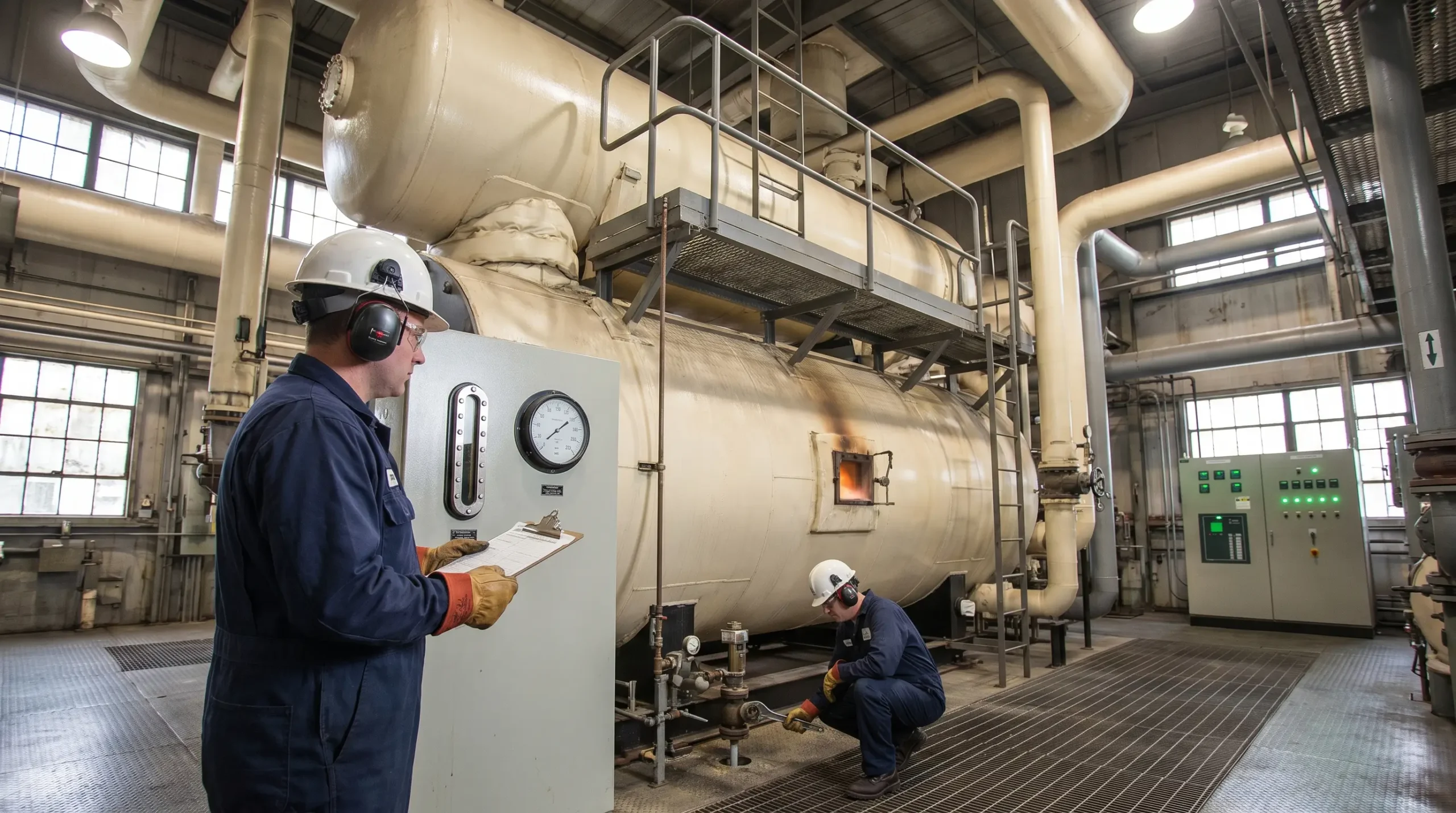
A packaged watertube boiler rated for 60,000 pounds of steam per hour holds somewhere between 12,000 and 15,000 pounds of water inside its drum and generating tubes — pressurised to roughly 350 psig and heated to 440°F. That water is not liquid the way a bathtub is liquid. It is liquid only because the pressure above it will not let it become steam. Breach the envelope by a quarter of an inch and the water inside sees atmospheric pressure for the first time in its life. In the fraction of a second it takes to flash to vapour, that water expands around 1,600 times in volume. Every fired pressure vessel on every site runs with that potential energy locked inside its shell every minute of every shift.
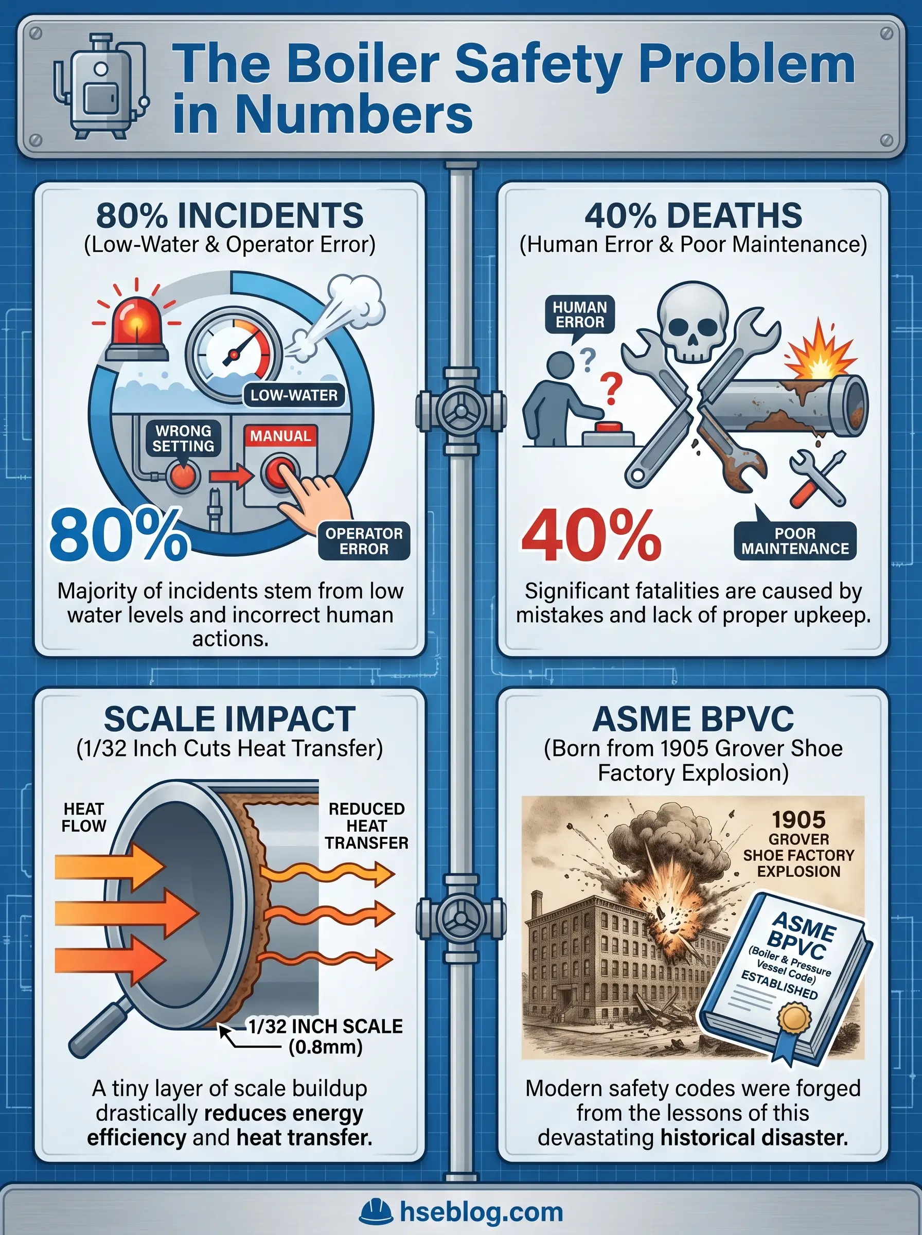
The consequences of releasing that energy uncontrolled are not theoretical. Boiler explosions have killed crews, levelled buildings, and shut plants down for months. What makes the incident pattern harder to accept is the cause distribution: National Board of Boiler and Pressure Vessel Inspectors data shows that roughly 80% of reported industrial boiler accidents trace back to low-water condition and operator error — two failure modes that can be engineered and managed out. This guide walks through why boilers fail, the early warning signs that precede most incidents, the regulatory framework that governs boiler safety, and the layered prevention approach that keeps pressure vessels inside their design envelope. The scope is industrial and commercial steam and hot water boilers, not domestic appliances.
Why Boiler Safety Matters: The Stored Energy Problem
Every fired pressure vessel on a site is an energy store. The water inside is not just a working fluid — it is restrained vapour. The moment the vessel boundary fails, every cubic inch of that water above the atmospheric boiling point converts to steam instantly. That is why a relatively modest industrial boiler can destroy the building around it if containment lets go.
The code the industry still works under today exists because of exactly this mechanism. In January 1905, the Grover Shoe Factory in Brockton, Massachusetts exploded, killing 58 workers and injuring more than 150. That incident, along with several other early-twentieth-century failures, pushed the American Society of Mechanical Engineers to publish the first Boiler and Pressure Vessel Code in 1914. The 2025 edition of the ASME BPVC carries that lineage forward and becomes mandatory for items manufactured or altered to its rules from 1 January 2026.
The uncomfortable pattern in modern incident statistics is that boiler technology has improved far faster than the operational practices governing it. Failures today rarely come from unknown metallurgy. They come from bypassed interlocks, untreated feedwater, skipped low-water cutoff tests, and operators who have never run a cold-start procedure from the written SOP.
How Boilers Fail: The Two Failure Modes
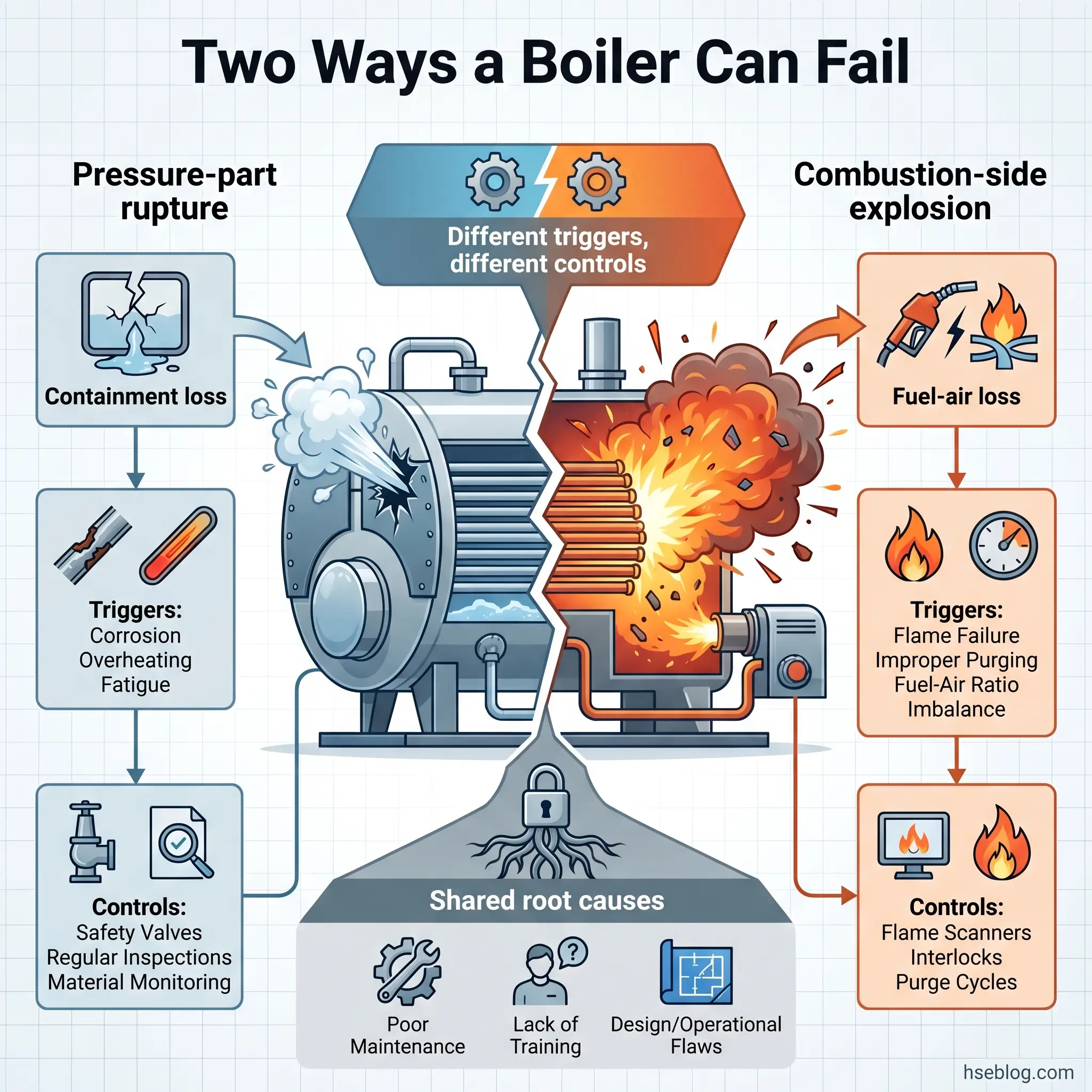
Every boiler failure eventually comes down to one of two physical events. Getting clear on which one you are trying to prevent is what separates structured diagnostics from reactive firefighting.
The first is pressure-part failure — a rupture of the pressure envelope itself. A tube splits, a drum deforms, a header cracks, or a shell lets go. The working fluid escapes through the breach, and whatever water in the vessel is above atmospheric saturation temperature flashes instantly. Pressure-part failure is a structural event driven by loss of containment.
The second is combustion-side failure — a furnace or fireside explosion. Here the pressure envelope itself is intact. The damage comes from an uncontrolled ignition of accumulated fuel inside the firebox, which can breach tubes or shell from the outside. Combustion explosions are driven by loss of fuel-air control.
The same root cause can trigger either mode. Poor maintenance can allow a tube to fail from scale overheating (pressure-part mode) or let a burner management interlock degrade until a fuel-rich start-up ignites the furnace (combustion mode). Knowing which mode you are defending against in any given scenario determines which controls matter.
| Failure Mode | Typical Trigger | Typical Consequence |
|---|---|---|
| Pressure-part rupture | Low-water overheating; corrosion thinning; overpressure; metallurgical defect | Tube or drum failure; instantaneous steam release; potential catastrophic rupture |
| Furnace / fireside explosion | Inadequate pre-purge; flame failure without trip; bypassed BMS interlock; leaking fuel valve | Firebox overpressure; refractory blowout; potential external tube breach |
Common Causes of Boiler Failure
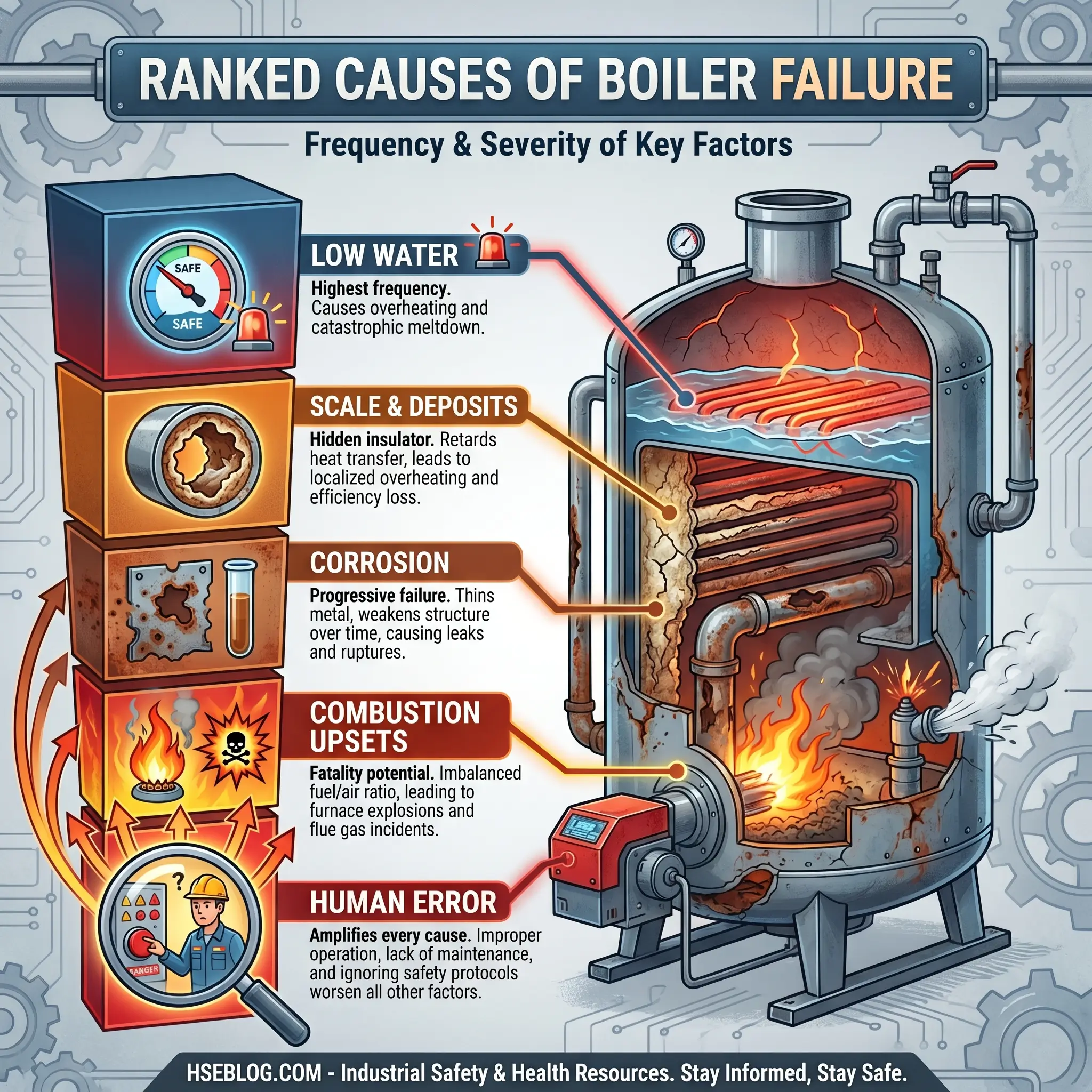
If National Board incident data is grouped by cause family, the pattern is remarkably stable year over year: water-side failures and combustion-side failures together account for the majority of serious events, and within each, a small number of mechanisms drive most outcomes. The sections below order them by how often they appear as primary contributors.
Low Water Condition
When a steam boiler loses water below the safe level, the metal above the water line — tube crowns, waterwall panels, the furnace crown sheet in firetube units — is no longer being cooled by a phase-change medium. Firebox temperatures climb past the yield strength of the steel within minutes. The metal deforms, sags, and eventually ruptures.
The most dangerous second-order effect is what happens next. An operator sees a low-water alarm, panics, and opens the feedwater valve. Cold water hitting steel 300°F above its design temperature flash-evaporates on contact, and the resulting pressure spike can tear open a tube or collapse a crown sheet. The moment a boiler is suspected of running dry, the only correct response is to secure fuel and leave water alone.
Common triggers include feedwater pump failure, a modulating feedwater control valve sticking closed, isolated water-column valves, sudden load demand outrunning feedwater capacity, an LWCO float fouled by sludge, and — the thread running through most incident reports — an operator who did not catch the gauge-glass drop in time.
Scale, Sludge, and Deposit Formation
Hardness minerals in feedwater (calcium, magnesium, silica) precipitate onto the hottest heat-transfer surfaces, forming scale. U.S. Department of Energy guidance indicates that even 1/32 inch of scale raises fuel consumption by around 2%, but the safety consequence is worse. Scale is a thermal insulator. The tube metal beneath it sees less cooling from the water side, and its metal temperature rises. Localised overheating then follows the same path as gross low-water: metallurgical degradation, creep, rupture.
Sludge settles in low-flow areas — the bottom of the mud drum, the base of water legs in firetube boilers, inside LWCO float chambers. On one overhaul at the steam house, the LWCO float came out fouled with sludge to the point it would no longer drop under an empty chamber. The boiler had been running for months with a device that was there to save it from running dry and physically could not do its job.
Corrosion and Metallurgical Degradation
The corrosion mechanisms worth recognising in the field include:
- Oxygen pitting. Dissolved oxygen attacks tubes, particularly in economisers and during wet-layup periods. Pin-hole leaks develop; eventual tube failure follows.
- Caustic embrittlement. High local concentrations of sodium hydroxide attack stressed riveted or welded joints. Rare in modern welded construction but still observed in older installations.
- Hydrogen damage. In high-pressure utility units, acidic under-deposit conditions allow atomic hydrogen to penetrate the tube wall and decarburise the steel. Characteristic “window” failures develop with no wall-thinning warning.
- Stress corrosion cracking. Superheater and reheater tubes operating at temperature under stress, in the presence of specific ionic contaminants.
- Flue-gas-side erosion. Fly ash and sootblower impingement thin tubes from the outside in.
Overpressure and Safety Valve Failure
The safety or pressure relief valve is the only device standing between a malfunctioning pressure control and a rupture. Its job is non-negotiable and it has to work the first time, every time, on demand.
Safety valves fail in a small number of predictable ways: set pressure drifts as internal spring components age; seats foul with scale or corrosion products until the valve will not lift cleanly; leaking seats erode until the valve can no longer reseat; an operator tampers with the locking mechanism. The worst failure of all is an isolation valve installed between the boiler and the safety valve — a practice that OSHA 29 CFR 1910.169 prohibits outright and that still surfaces in audits.
Combustion-Side Failures (Furnace Explosions)
Every furnace explosion with a published root-cause report comes back to the same handful of contributors: inadequate pre-purge of the firebox before re-ignition, a bypassed or defeated burner management system interlock, flame failure undetected or overridden, or poor fuel atomisation producing pockets of rich mixture. Start a burner into an unpurged furnace containing leaked fuel, and the ignition source finds a combustible mixture in the one place you never want one.
The Transport Malta Marine Safety Investigation Unit’s 2025 report on the January 2024 fatal boiler incident aboard the tanker Torc illustrates the pattern. A starboard boiler failed during a fuel changeover sequence; investigators found that the crew had misperceived the risks of the transition and placed excessive confidence in their safety barriers. One crew member was killed. The mechanism — a fuel-side event during transition — is not unique to ships. Every industrial plant runs fuel changeovers during maintenance, during emergency diesel backup, during seasonal swings.
Component-Level Failures
Beyond the major mechanisms, individual components can fail in ways that propagate into larger events: burner atomising nozzles plugging, fuel pressure regulators drifting, economiser coils developing pinhole leaks that dump water into the flue path, pressure gauge indicators reading low, sight glasses cracked and misinterpreted, PLC control loops corrupting, refractory spalling into the fuel path.
Human Factors: Operator Error and Inadequate Training
The National Board’s own analysis attributes nearly 40% of boiler-related deaths and accidents directly to human error or poor maintenance. That number is not a slogan. It is the ceiling that bounds how much metallurgy, code compliance, and instrumentation can do for you.
The human-factor patterns driving incidents keep recurring:
- Bypassing or “jumping out” an interlock during a troublesome start-up, and never restoring it.
- Unauthorised variations from written start-up procedures — “the book says 5 minutes pre-purge but we’ve always done 2.”
- No management-of-change control when a component is replaced with a non-identical substitute.
- Operator training that covers gauge reading and water management but never walks through a fuel-train interlock test or a mock auto-to-manual changeover.
- Shift-handover logs that degenerate into checkmarks because the incoming shift trusts the outgoing shift.
| Cause Family | Typical Incident Frequency | Typical Severity |
|---|---|---|
| Low water condition | High | High — potential catastrophic rupture |
| Scale, sludge, deposits | High | Medium-High — tube failure, eventual rupture |
| Corrosion | Medium | Medium-High — progressive to sudden failure |
| Overpressure / relief valve failure | Low-Medium | Very High — pressure envelope rupture |
| Combustion / furnace explosion | Medium | Very High — fatality potential |
| Component-level failures | Medium | Low-Medium — usually contained |
| Human factors (cross-cutting) | Very High | Variable — amplifies every other cause |
Early Warning Signs of Boiler Failure
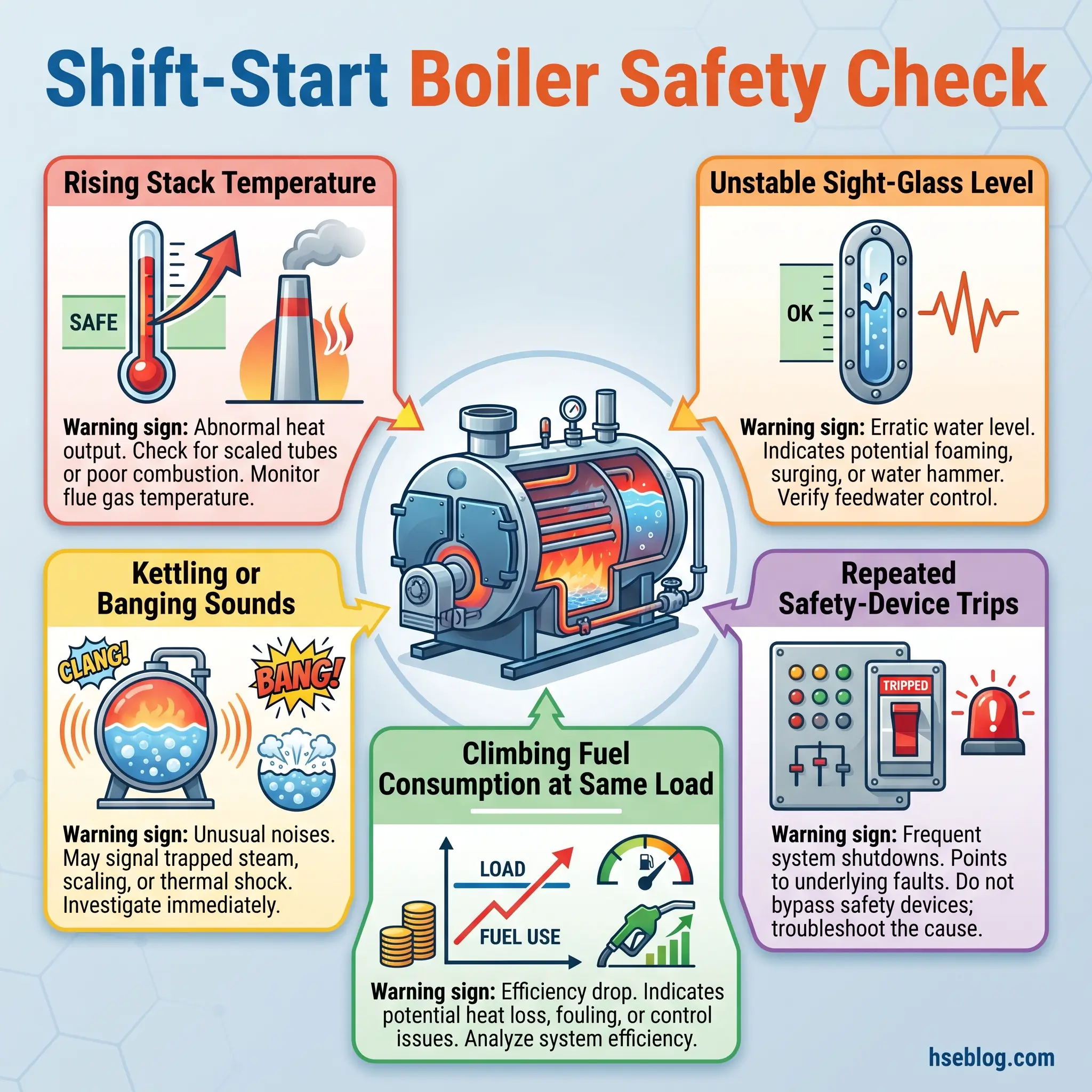
Most boiler incidents do not happen without warning. They happen when the warning signs are observed but not acted on, or when no one on the shift was trained to recognise them for what they are. The list below is what a competent operator checks in the first ten minutes of every shift — and what an HSE officer watches for during a plant walk.
- Unexplained rise in stack or flue gas temperature — likely cause: scale or soot fouling on the fire side, reducing heat transfer. Action: schedule cleaning at next outage and verify combustion tuning.
- Fluctuating or unstable water level in the sight glass — likely cause: carryover, foaming from dissolved solids, feedwater control hunting, or sludge buildup. Action: check feedwater chemistry; verify LWCO function; sample boiler water.
- Rust-coloured water or visible sludge on bottom blowdown — likely cause: internal corrosion or ineffective feedwater treatment. Action: test dissolved iron, pH, sulphite; review chemical dosing.
- Kettling, banging, or popping noises — likely cause: localised overheating, scale on tubes, or water hammer in steam lines. Action: inspect at next cold shutdown; do not dismiss as “normal.”
- Repeated tripping of safety interlocks or relief valves — likely cause: a control system drifting out of range, a failing sensor, or a genuine process excursion. Action: do not normalise the alarm; investigate root cause before accepting the next trip.
- Sudden rise in fuel consumption at the same load — likely cause: efficiency loss from scale, soot, excess air drift, or feedwater contamination. Action: combustion analysis and heat-loss audit.
- Visible leaks at joints, gasket faces, or tube ends — likely cause: corrosion, thermal cycling fatigue, or gasket degradation. Action: never isolate with makeshift measures; schedule repair under permit.
- Drifting combustion readings (high CO, low or high O₂) — likely cause: burner maladjustment, air register drift, or a developing fuel-side issue. Action: retune combustion and inspect the burner.
Watch For: A safety device that trips and resets, trips and resets, trips and resets, is not behaving erratically. It is detecting a process excursion that has not yet been resolved. Every additional trip is a data point the investigation will use after the incident — act on it before then.
Regulatory Framework for Boiler Safety
Boiler safety sits inside a layered regulatory framework combining construction codes (how the vessel is built), in-service codes (how it is inspected and maintained), combustion-specific standards (how the fuel side is controlled), and occupational safety regulations (who is responsible). Understanding what each document actually requires — not just its name — is what separates a real compliance position from a shelf full of binders.
ASME BPVC Section I governs construction of power boilers (steam above 15 psig or high-temperature water above 160 psig / 250°F). A new industrial boiler cannot be placed in service without an ASME stamp and, in most jurisdictions, National Board registration. Section IV covers heating boilers at or below 15 psig steam. Section VII provides recommended care-of-power-boilers guidance and maps directly to many of the operator-side controls in this article.
NFPA 85 takes over where combustion hazards dominate. It applies to boilers with fuel input at or above 12.5 MMBtu/hr and is the authoritative document for burner management systems, purge sequences, interlock testing, and commissioning plans. Below that threshold, ASME CSD-1 (Controls and Safety Devices for Automatically Fired Boilers) sets comparable requirements for smaller automatically fired units.
OSHA’s pressure-vessel provisions at 29 CFR 1910.169 and 29 CFR 1926.29 require pressure vessels to be certified by an insurance company or regulatory authority, built to ASME BPVC, and fitted with protective relief devices that are never isolated from the vessel. Where a boiler is part of a covered highly hazardous chemical process, OSHA 29 CFR 1910.119 Process Safety Management layers on process hazard analysis, mechanical integrity, and management-of-change requirements.
In the UK, the Health and Safety Executive publishes INDG436 — Safe Management of Industrial Steam and Hot Water Boilers, which sets the duty on workplace managers to assess and manage boiler risks under the Pressure Systems Safety Regulations 2000 and the associated Approved Code of Practice L122. The companion technical guidance BG01, produced jointly by HSE, the Combustion Engineering Association, and SAFed, defines the competent-person concept, operator competency (including BOAS certification), and unattended-operation requirements.
| Standard | Jurisdiction / Scope | What It Requires in Practice |
|---|---|---|
| ASME BPVC Section I | International; power boilers | Stamped construction; NB registration; hydrostatic testing |
| ASME BPVC Section IV | International; heating boilers ≤15 psig | H-stamp certification; construction rules |
| ASME BPVC Section VII | International; care of power boilers | Recommended operational practice and internal chemistry |
| NFPA 85 | US-origin, widely adopted; ≥12.5 MMBtu/hr | BMS, purge sequence, interlock commissioning and testing |
| ASME CSD-1 | Units ≤12.5 MMBtu/hr automatically fired | Combustion safety controls and interlock testing |
| National Board Inspection Code | US states / Canadian provinces adopting | In-service inspection, repair, alteration |
| OSHA 29 CFR 1910.169 / 1926.29 | United States | Certified vessels; no isolation on relief path |
| HSE INDG436 / ACOP L122 | United Kingdom | Risk management under PSSR 2000 |
| HSE/CEA/SAFed BG01 | United Kingdom | Competent-person, BOAS operator training |
The National Board’s published guidance on the top boiler and combustion safety issues to avoid maps closely onto the failure modes above, and the ASME standards portfolio is summarised at the ASME BPVC standards page. Federal pressure-vessel requirements in the US are consolidated at the OSHA pressure vessels standards page.
Prevention: A Layered Approach to Boiler Safety
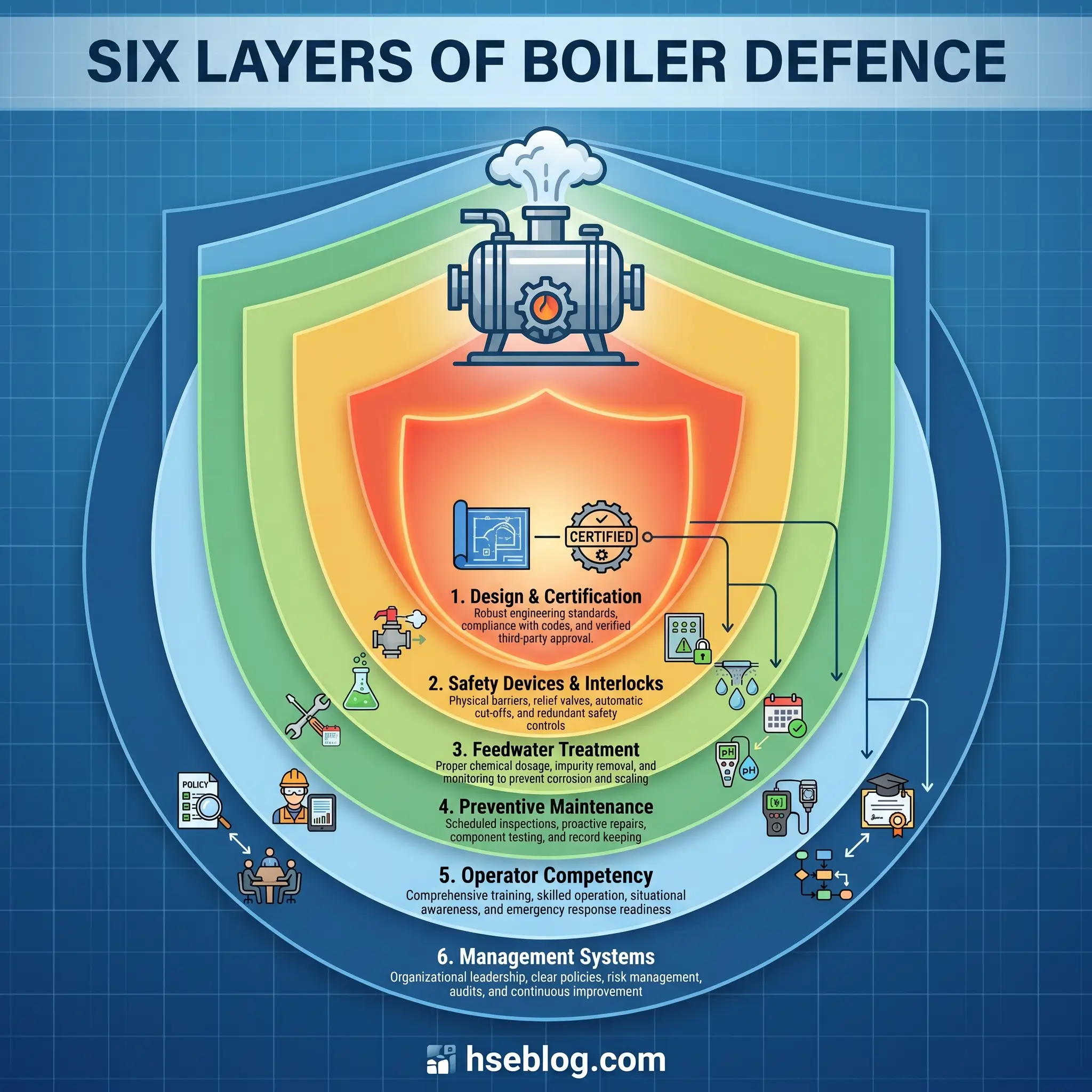
Boiler safety is not one defence. It is six. Each layer covers a specific family of failure modes, and each layer has to hold independently — because a boiler incident is almost always the result of more than one barrier having already failed.
Layer 1 — Design, Installation, and Certification
Nothing that is wrong at installation gets fixed at operation. A boiler that is not ASME-stamped, not National Board registered, not hydrostatically tested before commissioning, or not sited with adequate clearances and explosion-relief routing is a vessel the site will fight for the rest of its operating life. INDG436 frames this as a duty to ensure the system remains safe throughout its life — and that duty begins before fuel is ever lit.
Layer 2 — Safety Devices and Interlocks
Modern boilers rely on a specific stack of safety devices, and redundancy is designed in. Anything less than what follows is below current code expectation for industrial units:
- Safety/relief valves sized to full firing rate, tested at the jurisdictional interval (typically annually by manual lift or triennially by certified removal and bench test).
- Primary and auxiliary low-water cutoffs — one float-type and one probe-type, or two independent probe devices — with the primary on a blowdown-testable arrangement.
- High-limit pressure and high-limit temperature controls independent of operating controls.
- Flame scanner and burner management system with individual main and pilot fuel valves and proof-of-closure.
- Low and high fuel gas pressure switches; combustion air proving switch.
- Emergency shutdown accessible outside the boiler-room door.
Layer 3 — Feedwater Treatment and Water Chemistry
Water chemistry is a safety control, not an efficiency optimisation. Without deaeration, dissolved oxygen attacks economiser tubes from day one. Without softening or demineralisation, hardness scales on the hottest heat-transfer surfaces. Without pH and alkalinity control, corrosion goes straight to the pressure envelope. Blowdown frequency — whether manual bottom blowdown on a shift schedule or automated continuous surface blowdown — controls the total-dissolved-solids ceiling the boiler runs at. Coordinated phosphate or all-volatile treatment is standard at higher pressures.
Layer 4 — Preventive Maintenance and Inspection
A defensible maintenance programme maps directly to regulatory minimums and operator-level practice:
- Daily: operator checks on water level, steam pressure, flame quality, auxiliary operation, and visible leaks.
- Weekly: LWCO bottom blowdown and quick-drain test to confirm burner trips on simulated low water.
- Monthly: full function test of safety interlocks; verification of pressure and temperature controls against calibrated reference.
- Semi-annual: external inspection under pressure.
- Annual: internal inspection on drum and furnace surfaces; safety valve testing; hydrostatic test when required after repairs or at inspection authority direction.
Layer 5 — Operator Competency and Procedures
Industry incident data keeps pointing back to the person at the controls. The prevention measure is competency built and maintained:
- Jurisdictional operator licensing where required (US states with boiler operator laws; UK BOAS scheme).
- Written, current, cold and hot start-up procedures followed without deviation.
- Management of change control covering any modification, substitution, or temporary bypass.
- Mock drills covering emergency shutdown, auto-to-manual changeover, and loss-of-feedwater scenarios.
- Shift handover logs with defined fields, not free text.
A new operator in the steam house once asked why we still practised manual water-level control every quarter when the feedwater system was fully automated. The answer is that on the day the automation fails — and it will — the boiler cannot wait for the person in the control room to learn a skill they never had.
Layer 6 — Management Systems and Safety Culture
The organisational layer is what holds the other five in place: pre-startup safety review after any outage; control-of-defeat procedures governing what can be bypassed and by whom; auditable maintenance records that survive an inspection; near-miss reporting that actually gets used to retune procedures. Published incident investigations repeatedly find that the immediate technical cause was enabled weeks or months earlier by a management-system failure that no one corrected.
Audit Point: If a site cannot show the last weekly LWCO blowdown record and the last monthly safety-interlock function-test record on demand, the paper layer of the defence has already failed — whatever the hardware is doing.
Responding to a Boiler Emergency
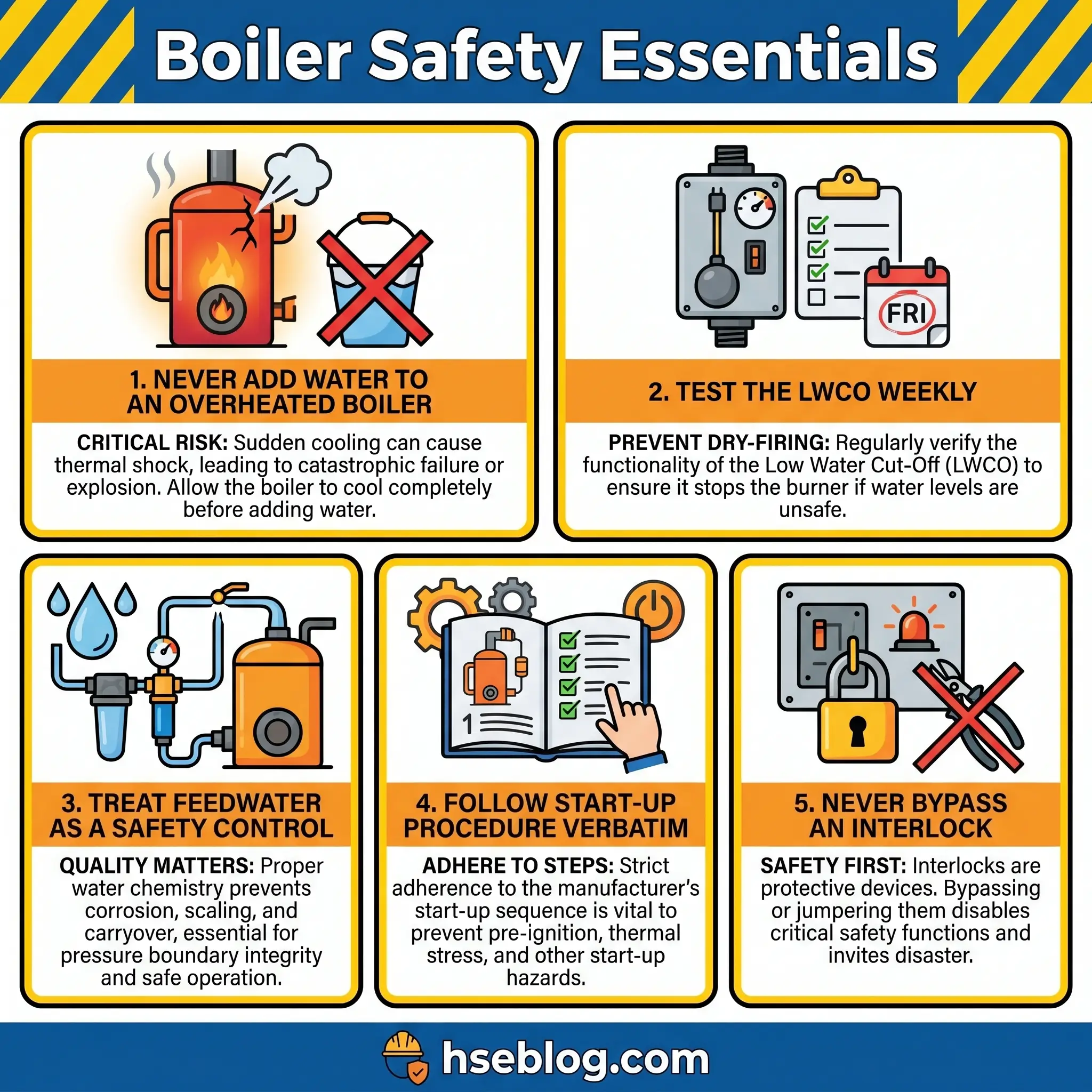
If a serious abnormality develops — suspected low-water overheating, unexplained pressure excursion, fuel-side incident, visible structural distress — the response is specific and brief:
- Do not add water to a boiler suspected of low-water overheating. Flash evaporation of feedwater on superheated metal can rupture the vessel.
- Secure the fuel via the emergency shutdown or manual main fuel valves. Confirm the BMS has closed main and pilot trains.
- Isolate the boiler from the steam header; close makeup water and blowdown lines only if safely accessible.
- Evacuate personnel from the boiler room and surrounding areas; establish a safe perimeter.
- Notify the jurisdiction’s inspection authority, the insurance inspector, and site emergency response.
- Preserve evidence — do not restart, clean, or disturb the boiler until root-cause investigation is complete.
Frequently Asked Questions
Conclusion
The lesson the industry keeps re-learning is that boiler safety is not a technology problem. The codes work. The metallurgy works. The safety devices work. What breaks, over and over, is the discipline of operating the system the way it was designed to be operated — testing the LWCO on schedule, not bypassing the interlock that keeps tripping, treating the feedwater as a safety control, following the cold-start procedure as written, reporting the near-miss the first time it happens instead of after the third.
The single highest-impact change any site can make is to elevate operator competency from a checklist item to an engineering discipline. That means certified training that covers fuel-train safety as rigorously as water management, documented procedures that are followed without improvisation, management of change that catches every modification before it goes live, and a shift-handover culture that treats information transfer as load-bearing. The 80% of boiler incidents driven by low-water and operator error is not a metallurgy problem waiting on better steel. It is a decision — made shift by shift, on every site — about whether the people at the controls are set up to keep the pressure envelope intact.