

TL;DR
- Factor of safety (FOS) is the built-in safety margin between the maximum load a structure or equipment can handle and its rated working load
- FOS values typically range from 1.5 to 10 depending on the application, material, and consequence of failure
- Ignoring FOS leads to catastrophic collapses — most structural and lifting equipment failures trace back to exceeded safety margins
- Every scaffold, crane, sling, and pressure vessel on your site has an FOS built into its design — your job is to never erode it
- Understanding FOS transforms how you inspect, load, and authorize equipment use on site
I was standing beneath a suspended platform on a petrochemical shutdown in the Gulf when the rigger told me, casually, that the wire rope slings were “good for double the load.” He meant it as reassurance. What he didn’t understand was that he was describing the factor of safety — and that his “double the load” comment meant the sling was already at its absolute working load limit. One miscalculation, one dynamic shock, one corroded strand, and we’d be writing an incident report. Or worse.
Factors of safety are among the most misunderstood concepts on industrial job sites. Workers hear “rated for 5 tonnes” and assume the equipment will handle 5 tonnes under any condition, in any configuration, after years of wear. That assumption kills people. FOS is the engineered gap between what equipment is rated to carry during normal use and the point at which it actually fails. This article breaks down what factors of safety mean in practice, how they’re calculated, where they apply across HSE operations, and — critically — how site teams erode them without realizing it.
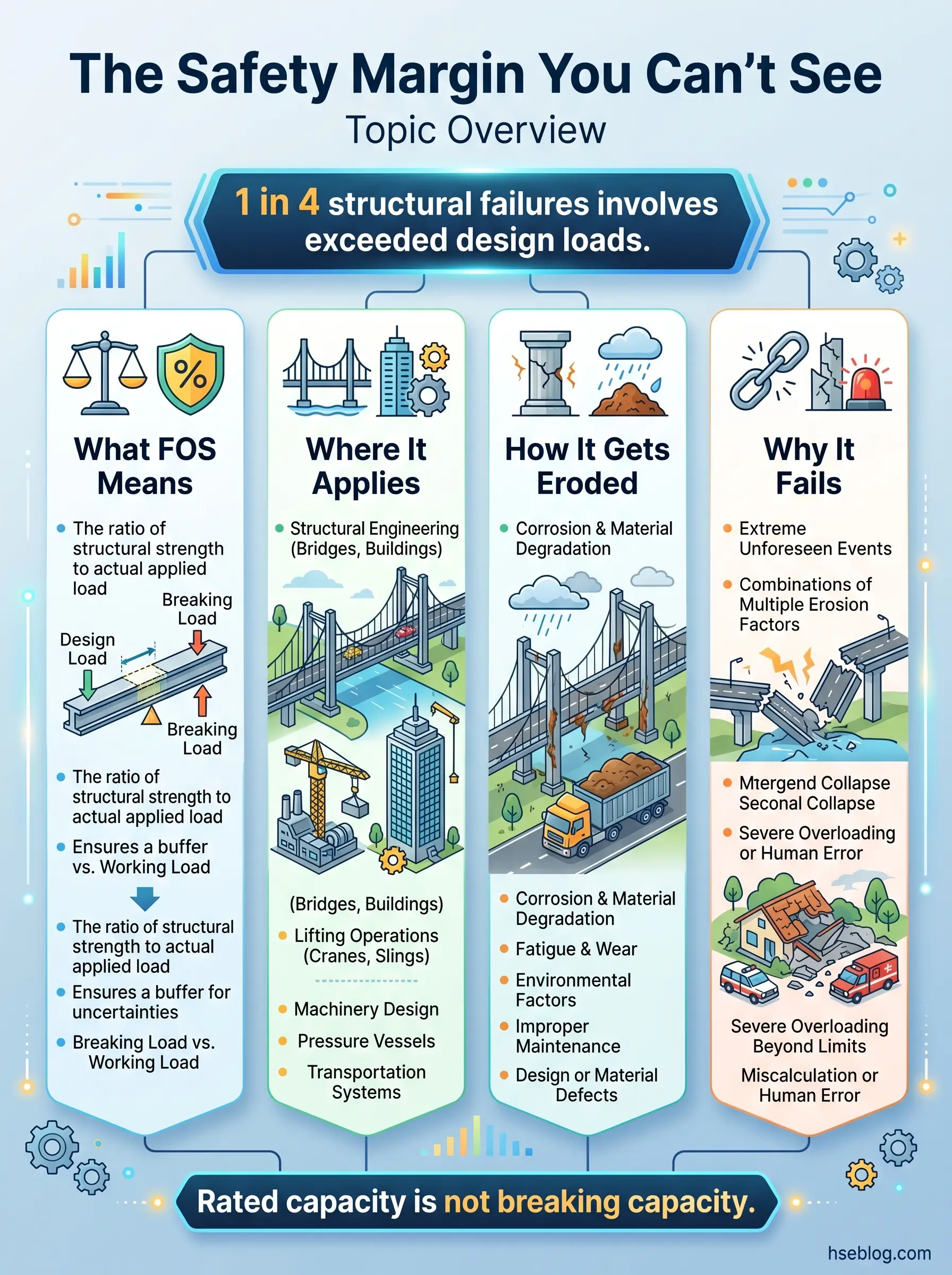
What Is a Factor of Safety (FOS) and How Does It Work?
A factor of safety is the ratio between the ultimate strength of a material or system and the maximum intended working load applied to it. It is, in its simplest form, an engineered buffer — a deliberate margin built into design so that real-world imperfections, unexpected loads, environmental degradation, and human error don’t push equipment past its breaking point.
The core formula that every HSE professional should know is straightforward:
FOS = Ultimate (Failure) Strength ÷ Maximum Allowable Working Load
A wire rope with an ultimate breaking strength of 10 tonnes and a safe working load (SWL) of 2 tonnes has an FOS of 5:1. That means the rope is designed to handle five times its rated load before catastrophic failure — but that margin is not “extra capacity.” It exists to absorb the variables that site conditions always introduce.
Here’s where the confusion starts. A 5:1 FOS does not mean you can load the rope to 4 tonnes and feel comfortable. The entire margin accounts for factors you cannot fully control:
- Material degradation: Corrosion, UV exposure, fatigue from repeated loading cycles, internal wire breaks invisible to the naked eye
- Dynamic loading: Shock loads from sudden lifts, swinging loads, or equipment jarring — dynamic forces can multiply static loads by 2x or more
- Environmental conditions: Extreme temperatures, chemical exposure, vibration, and moisture that weaken materials over time
- Manufacturing tolerances: No two components are identical; micro-variations in material composition and fabrication create performance spread
- Human error: Improper rigging angles, side-loading, dragging loads, using damaged equipment — the single largest variable on any site
Pro Tip: When I audit lifting operations, I ask riggers one question: “What’s the FOS on that sling?” If they can’t answer, they don’t understand the margin they’re working within — and that’s a stop-work conversation.
Common Factors of Safety Across HSE Applications
FOS values are not universal. They vary by industry, application, material type, consequence of failure, and governing standard. A pressure vessel designed to contain flammable gas carries a much higher FOS than a storage shelf in a warehouse — because the consequence of failure is catastrophically different.
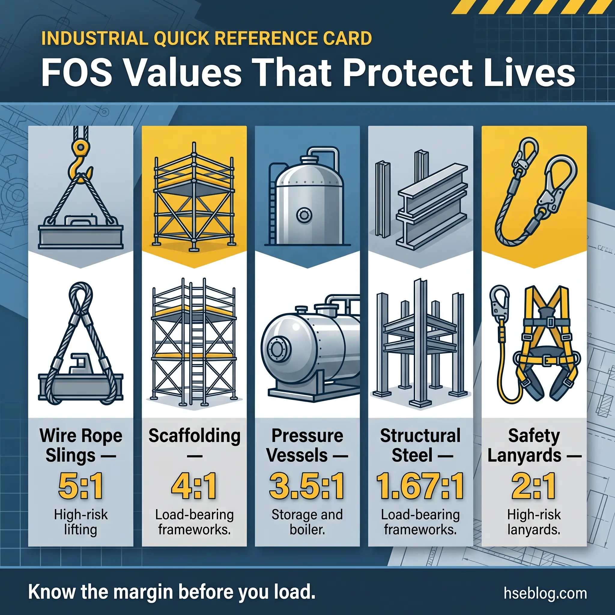
The following table summarizes typical FOS ranges across common HSE applications. These are reference values — always verify against the specific design standard and manufacturer specification for the equipment on your site.
| Application | Typical FOS | Governing Standard / Reference | Why This Value? |
|---|---|---|---|
| Wire rope slings | 5:1 | ASME B30.9 | Dynamic shock loads, abrasion, fatigue |
| Chain slings | 4:1 – 5:1 | OSHA 1926.251 / EN 818 | Impact loading, link wear |
| Scaffolding | 4:1 | OSHA 1926.451 / BS EN 12811 | Live loads, wind, worker movement |
| Pressure vessels | 3.5:1 – 4:1 | ASME BPVC Section VIII | Internal pressure, material creep |
| Structural steel | 1.67 – 2:1 | AISC 360 / Eurocode 3 | Well-understood loads, low variability |
| Lifting hooks | 4:1 – 5:1 | ASME B30.10 | Dynamic loads, point stress |
| Safety harness lanyards | 2:1 (on arrest force) | ANSI Z359.1 / EN 355 | Fall arrest shock, body weight variation |
| Concrete structures | 1.5 – 2:1 | ACI 318 / Eurocode 2 | Material variability, curing conditions |
| Crane booms | 3:1 – 5:1 | ASME B30.5 / EN 13000 | Dynamic loads, wind, boom length |
| Guardrails and handrails | 2:1 – 3:1 | OSHA 1926.502 / BS EN 13374 | Impact from falling worker |
Notice the pattern: applications involving dynamic forces, human life, or catastrophic failure consequences carry higher FOS values. Structural steel in a building frame gets a relatively low FOS because loads are predictable, well-analyzed, and static. A wire rope hoisting workers over a 40-metre drop gets a 5:1 FOS because the consequences of failure are irreversible and the loading conditions are less predictable.
How Factors of Safety Get Eroded on Site
This is where theory meets dirt. Every factor of safety is calculated under assumed conditions — new equipment, correct configuration, proper maintenance, and competent operation. On a real job site, those assumptions start deteriorating from day one. I’ve investigated structural failures where the original FOS was perfectly adequate on paper. The problem was never the design. It was what happened between installation and collapse.
Overloading Beyond Rated Capacity
The most direct way to erode FOS is simply exceeding the rated load. It sounds obvious, but it happens constantly — and it rarely happens by dramatic margin. Most overloading incidents involve loads that are 10–20% above the rated capacity. Workers assume that because the equipment didn’t fail last time, it won’t fail this time. That reasoning ignores cumulative fatigue. Every overload cycle consumes part of the safety margin permanently.
The following site-level mistakes cause overloading more often than most supervisors realize:
- Estimated load weights instead of verified weights: “It looks like about 2 tonnes” has preceded more rigging failures than I can count
- Ignoring rigging angle deductions: A sling at a 60° angle loses roughly 13% of its rated capacity — at 30°, it loses 50%
- Stacking loads on scaffolding platforms: Each additional item reduces the remaining margin; cumulative loading is the silent killer
- Using equipment as makeshift anchors: Tying off fall arrest systems to pipe supports or handrails not designed for arrest forces
- Water accumulation and debris: Rain, mud, concrete slurry, and stored materials on platforms add dead load nobody accounts for
Pro Tip: On every project I manage, I require load verification tags on any rigged load over 500 kg. The tag shows verified weight, sling configuration, angle deduction, and remaining FOS margin. It takes two minutes and has prevented dozens of overloads.
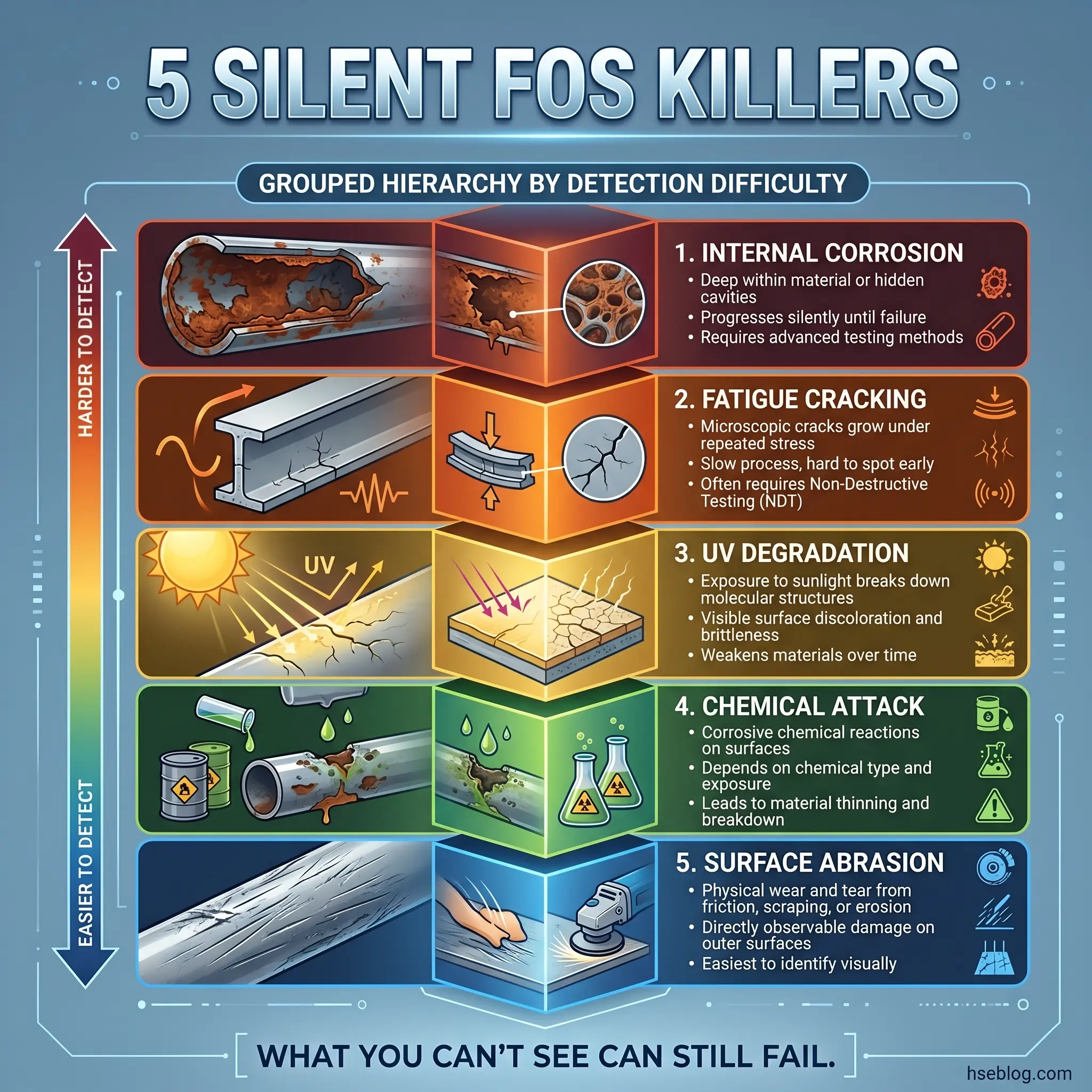
Material Degradation and Wear
FOS is calculated for new, undamaged equipment. From the moment a wire rope is first loaded, a scaffold tube is first erected, or a pressure vessel is first pressurized, degradation begins. The factor of safety does not get recalculated after years of service — but the actual margin shrinks.
Common degradation pathways that silently reduce FOS include:
- Corrosion: Surface and internal rust reduces the effective cross-section of steel components, lowering ultimate strength
- Fatigue cracking: Repeated loading and unloading creates micro-cracks at stress concentration points — welds, pin holes, bends
- UV degradation: Synthetic slings, fall arrest lanyards, and polymer components lose tensile strength with prolonged sun exposure
- Chemical attack: Acid mist, alkaline wash-down water, solvents, and hydrocarbon contact deteriorate metals and polymers
- Abrasion and mechanical damage: Slings dragged over sharp edges, ropes run over rough surfaces, scaffold tubes dented by impacts
Equipment that passes a visual inspection is not necessarily equipment that retains its original factor of safety. Visual checks catch gross damage — not the 30% strength reduction from internal corrosion you can’t see.
Unauthorized Modifications and Improper Repairs
I once walked a scaffold on a construction site in Northern Europe and found that a crew had removed diagonal bracing from three bays to create a wider work area. They’d done it the previous night shift. Nobody logged it. Nobody recalculated the structural capacity. The scaffold was now carrying the same load — with a significantly reduced factor of safety. That’s how collapses happen: not from dramatic overloading, but from quiet modifications by people who don’t understand what they’re changing.
Field modifications that compromise FOS are disturbingly routine:
- Removing structural bracing from scaffolds, temporary works, or falsework to improve access
- Welding repairs on lifting equipment without recertification or metallurgical testing
- Splicing wire ropes in the field instead of replacing them
- Repainting corroded structural members to conceal damage rather than addressing it
- Substituting components with non-equivalent parts — different grade bolts, lighter gauge materials, shorter pins
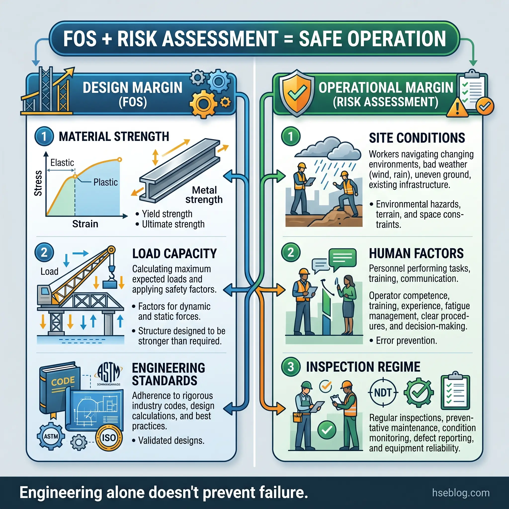
The Relationship Between FOS and Risk Assessment
Factors of safety and risk assessment are two sides of the same coin. FOS addresses the engineered margin against failure. Risk assessment addresses the operational margin against harm. Neither works properly without the other.
A scaffold with a 4:1 FOS is safe by design — but a risk assessment might reveal that the scaffold is erected on unstable ground, exposed to high wind loads, or accessed by more workers simultaneously than the design assumed. The FOS doesn’t change. The actual risk does.
When I conduct risk assessments on critical structures and lifting operations, I evaluate FOS as one layer of the control framework — not the only layer. The assessment must also address:
- Whether the original design assumptions still hold: Has the ground condition changed? Has the load profile shifted? Has the environment become more corrosive?
- Whether inspection and maintenance regimes are adequate: A 5:1 FOS means nothing if the equipment hasn’t been inspected in 18 months
- Whether users understand the rated limits: Competent operators know the FOS. Untrained operators treat the SWL as a suggestion
- Whether administrative controls support the engineering: Permit-to-work systems, load management plans, exclusion zones, and pre-use checklists protect the FOS from being eroded by operational decisions
A factor of safety protects against unknowns in the design. A risk assessment protects against unknowns in the operation. You need both.
Pro Tip: During pre-task planning, I ask one question that catches most teams off guard: “What’s the weakest link in this operation, and what’s its FOS?” If nobody can answer, the planning isn’t finished.
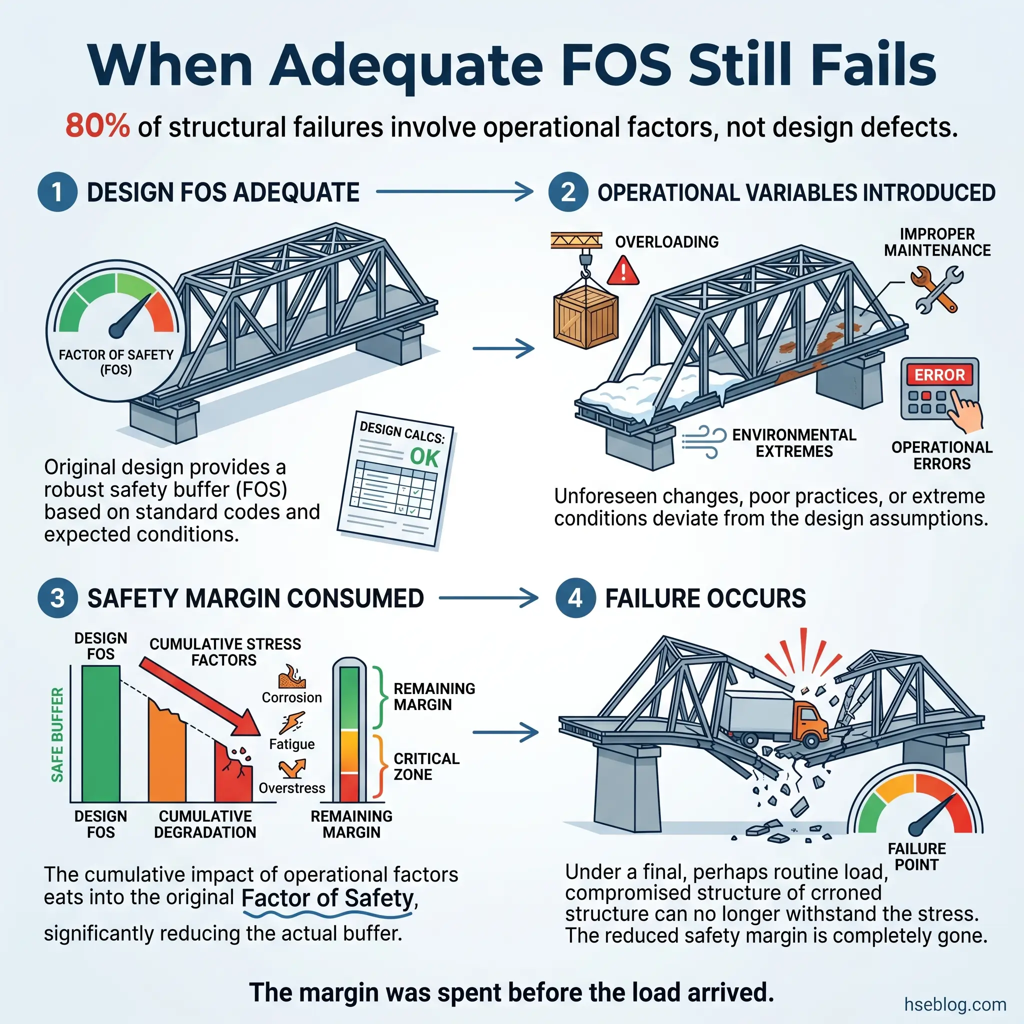
Why Equipment Fails Despite Having an Adequate Factor of Safety
This is the question I get asked most after incident investigations. The crane had a 4:1 FOS. The scaffold met design standards. The sling was rated for the load. So why did it fail?
The answer, almost every time, is that something on site consumed the safety margin that the FOS was supposed to provide. The design was correct. The operation was not. Understanding the gap between design intent and operational reality is what separates competent HSE professionals from people who just read data plates.
The most common failure scenarios involve combinations of the following — rarely is a single factor responsible:
- Cumulative overloading: Repeated lifts at 90–100% of SWL cause fatigue that a single-event load test wouldn’t reveal
- Unaccounted dynamic forces: Wind gusts on a crane load, sudden stops during hoisting, or impact during landing generate forces 2–3 times the static load
- Inspection failures: Missed corrosion, undetected cracks, overlooked deformation — the equipment appeared serviceable but had already lost significant margin
- Environmental factors beyond design scope: Seismic activity, extreme temperature swings, chemical contamination not anticipated in the original design
- Incorrect assembly or installation: A scaffold erected with tubes in the wrong orientation, a sling reeved at a sharper angle than planned, a bolt torqued below specification
Case: Crane Outrigger Failure
On a tank farm project in Southeast Asia, a 100-tonne mobile crane was lifting a heat exchanger when the outrigger pad punched through what appeared to be solid compacted ground. The crane’s structural FOS was adequate. The rigging was correct. The load was within the crane’s capacity chart. What failed was the ground bearing capacity — something the crane’s design factor never accounted for, because ground conditions are an operational variable, not a design variable. The crane tilted 12 degrees before the operator executed an emergency lower. No injuries, but the heat exchanger was a write-off and the project lost eleven days.
That incident reinforced a principle I carry into every lift plan review: the factor of safety on the equipment is only as good as the weakest element in the entire lifting system — and that element is often not the equipment itself.
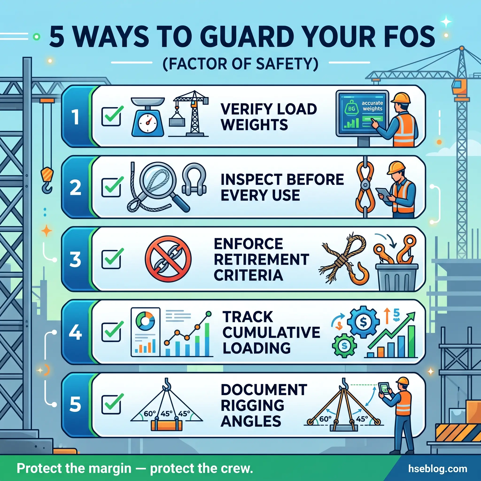
How to Protect and Verify Factors of Safety on Site
Knowing what FOS is matters less than knowing how to protect it under real conditions. Every inspection, every lift plan, every scaffold handover, and every pressure test is an opportunity to verify that the designed safety margin is still intact. The following practices are what I’ve seen consistently separate sites with zero structural failures from sites that keep having “unexpected” collapses.
Inspection and Certification Discipline
The single most effective way to protect FOS is rigorous, scheduled, and documented inspection of every safety-critical item. Visual inspection catches surface damage. But protecting FOS requires going deeper.
The following inspection practices directly protect the engineered safety margin:
- Third-party load testing at defined intervals: Wire ropes, chains, shackles, and lifting beams must be proof-tested and recertified per LOLER (UK), OSHA 1926.251 (US), or equivalent
- Non-destructive testing (NDT) for hidden damage: Magnetic particle inspection, ultrasonic testing, and dye penetrant testing detect subsurface cracks and corrosion that visual checks miss
- Colour-coded inspection tagging: Implement quarterly colour codes on slings, shackles, and lifting accessories so expired items are immediately identifiable
- Pre-use checks by competent persons: Every scaffold, crane, and lifting accessory gets a documented check before each shift — not a glance, a structured check against a checklist
- Retirement criteria enforcement: Wire ropes with more than 6 broken wires in one lay length, slings with visible cuts exceeding 10% of the width, chains with stretch exceeding 3% — retire them, no exceptions
Load Management and Operational Controls
Engineering controls protect FOS at the design stage. Operational controls protect it at the usage stage. Both layers must function simultaneously.
Effective load management practices that I’ve implemented across multiple EPC projects include:
- Mandatory weigh verification for all lifts over 500 kg: No estimated weights. Use calibrated load cells or verified material certificates
- Rigging angle calculations documented in the lift plan: Sling angles below 60° from horizontal require formal re-rating of the sling capacity
- Exclusion zones enforced under suspended loads: No personnel within the drop zone — the FOS on the rigging doesn’t protect anyone standing beneath it if failure occurs
- Wind speed monitoring with defined stand-down thresholds: Most crane operations cease at sustained winds of 30–40 km/h, depending on the crane chart and load profile
- Cumulative load tracking on scaffolding platforms: Post the maximum platform load at every access point and assign a competent person to monitor compliance
Pro Tip: I require every lifting supervisor on my projects to carry a pocket sling angle chart — a laminated card showing capacity deductions at 30°, 45°, and 60°. It takes the guesswork out and protects the FOS at the point of rigging.
FOS in Pressure Systems: A Special Case
Pressure vessels, piping systems, and boilers deserve separate attention because the consequences of FOS failure are uniquely catastrophic. A scaffold collapse is localized. A pressure vessel rupture can kill everyone within a blast radius measured in tens of metres.
ASME Boiler and Pressure Vessel Code (BPVC) Section VIII specifies a minimum design factor of 3.5:1 for most unfired pressure vessels. This means a vessel rated for 100 psi operating pressure is designed to withstand at least 350 psi before rupture. That margin accounts for material creep, weld imperfections, corrosion allowance, cyclic pressurization, and emergency overpressure scenarios.
The critical factors that erode FOS in pressure systems are different from structural or lifting applications:
- Internal corrosion from process fluids: Wall thinning reduces the pressure-bearing cross-section — even millimetres of loss significantly reduce the FOS
- Creep at elevated temperatures: Metals operating above their creep threshold deform permanently under sustained load, reducing long-term strength
- Weld defects and hydrogen-induced cracking: Subsurface flaws in welds can propagate under pressure cycling, creating failure points invisible to external inspection
- Relief valve malfunction: If the pressure relief system fails, the vessel can experience pressures beyond its design margin — the FOS becomes the last line of defence
- Improper hydrostatic testing: Test pressures that exceed the design test factor can introduce damage, paradoxically reducing the FOS they were meant to verify
ASME BPVC Section VIII, Division 1 requires that unfired pressure vessels be hydrostatically tested at 1.3 times the maximum allowable working pressure (MAWP) to verify the design margin without causing permanent deformation.
Conclusion
Factors of safety are not numbers on a data plate. They are engineered survival margins — designed by people who understood that real-world conditions are never as clean as a calculation sheet. Every time a sling drags over a sharp edge, every time a scaffold carries more than its rated platform load, every time a pressure vessel skips its wall thickness survey — the FOS shrinks. And unlike a gauge or an alarm, there is no warning when the margin runs out.
The role of every HSE professional on every site is to understand what the factor of safety represents, know what erodes it, and actively protect it through inspection, competent supervision, load management, and uncompromising enforcement of rated capacities. The equipment was designed to keep people alive. Our job is to make sure we don’t undo that design with operational shortcuts.
I’ve seen the aftermath of structural failures where every piece of paper was in order — the certifications were current, the design was compliant, and the load chart said it was fine. What killed people was the gap between what was written and what actually happened on the ground. Factors of safety close that gap. But only if we respect them.