
TL;DR
- Inspect across three phases — material receiving, fabrication verification, and site readiness — before any steel leaves the ground.
- Verify concrete strength in writing — OSHA requires 75% minimum compressive design strength with written notification to the erector before columns go up.
- Match every piece to its MTR — heat number traceability from mill test report to installed member prevents grade substitution.
- Enforce hold points, not just witness points — anchor bolt position and foundation strength are hard stops, not optional attendances.
- Apply NDT by risk category — AISC 360-22 Chapter N5 mandates ultrasonic testing on CJP groove welds in tension; visual inspection alone is never sufficient for these connections.
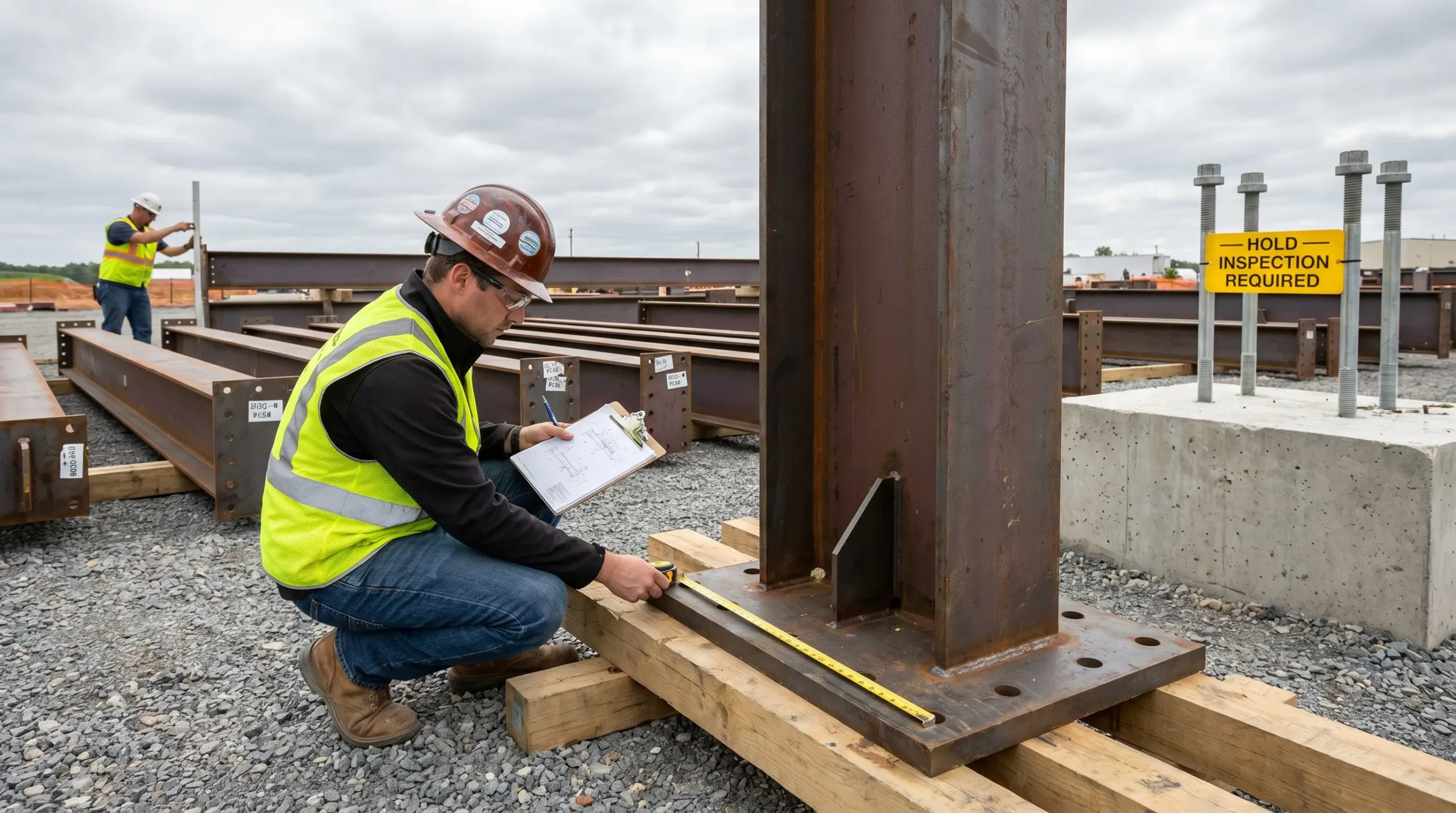
Pre-erected steel inspection is the systematic verification of steel materials, fabricated components, and construction site readiness before structural steel erection begins. It covers material receiving checks against mill test reports, fabrication quality verification against design drawings and welding codes such as AWS D1.1, and site-readiness assessment — including foundation cure strength, anchor bolt positioning, crane certification, and fall protection system readiness.
What Is Pre-Erected Steel Inspection and Why Does It Matter?
Under 29 CFR 1926.752(a), the controlling contractor must provide written notification that concrete in footings, piers, and walls has reached minimum compressive design strength before erection can begin (US jurisdiction). This is not a suggestion buried in guidance notes — it is a regulatory hold point with enforcement consequences, and it exists because column-base failures during early erection sequences have historically caused progressive structural collapses.
Pre-erected steel inspection sits at the boundary between fabrication completion and erection commencement. It is the last quality gate before structural elements become permanent parts of the building.
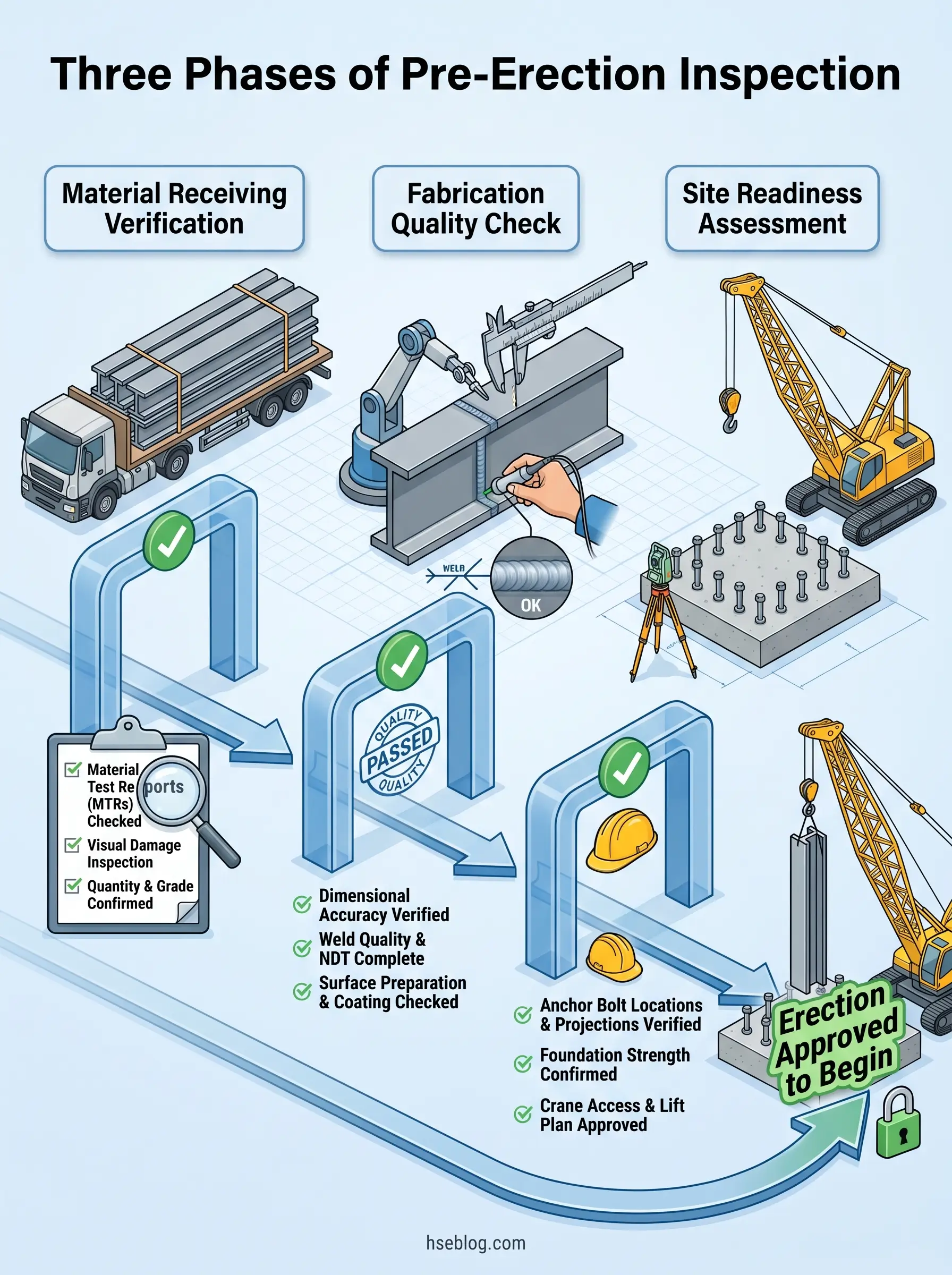
The inspection covers three distinct domains:
- Material verification — confirming that delivered steel matches specified grades, quantities, and condition requirements.
- Fabrication accuracy — checking that components meet dimensional tolerances, connection geometry, and weld quality standards.
- Site-readiness assessment — verifying that foundations, anchor bolts, equipment, and safety systems are prepared to safely receive steel.
Defects caught at this stage cost hours to resolve. The same defects discovered after erection — with steel bolted at height, cranes released, and follow-on trades mobilized — cost weeks and create life-safety hazards during corrective work.
Who Is Responsible for Pre-Erection Steel Inspection?
A consistent failure pattern across OSHA steel erection citations is confusion over who owns which inspection obligation. Organizations frequently assign “inspection” to the crane operator’s pre-lift check and miss the dedicated material-and-fabrication verification that should occur days before erection day.
OSHA’s Subpart R framework, AISC 360-22, and EN 1090-2 each assign responsibilities differently. The critical distinction in the US system is between QC (quality control, performed by the fabricator or erector) and QA (quality assurance, performed independently on behalf of the owner or authority having jurisdiction).
| Role | Primary Obligation | Governing Standard |
|---|---|---|
| Controlling contractor | Written notification of concrete strength; SER approval of anchor bolt modifications | 29 CFR 1926.752(a), 1926.755(b) (US) |
| Steel erector | Pre-erection field verification; connection installation QC | AISC 360-22 Chapter N — QC tasks |
| QA/QC inspector (independent) | Third-party verification of fabrication and erection quality | AISC 360-22 Chapter N — QA tasks |
| Structural Engineer of Record (SER) | Approval of anchor bolt repairs/modifications; design compliance oversight | 29 CFR 1926.755(b)(1) (US) |
| Responsible Welding Coordinator | Welding quality oversight, WPS compliance | EN 1090-2 (EU/UK) — IWE/IWT by execution class |
Under OSHA’s framework, the “competent person” for steel erection must be capable of identifying existing and predictable hazards and authorized to take immediate corrective action. This is a defined legal term — it carries personal liability, and it is not the same as a “qualified person” or “qualified rigger,” which have separate technical definitions under Subpart R.
Steel Material Receiving Inspection: What to Verify on Delivery
The most frequently skipped checks during material receiving are also the most consequential: dimensional spot-checks and transport damage assessment. Receiving crews under schedule pressure tend to verify piece count against the bill of materials and move on — confirming that everything arrived, but not that everything arrived undamaged and dimensionally accurate.
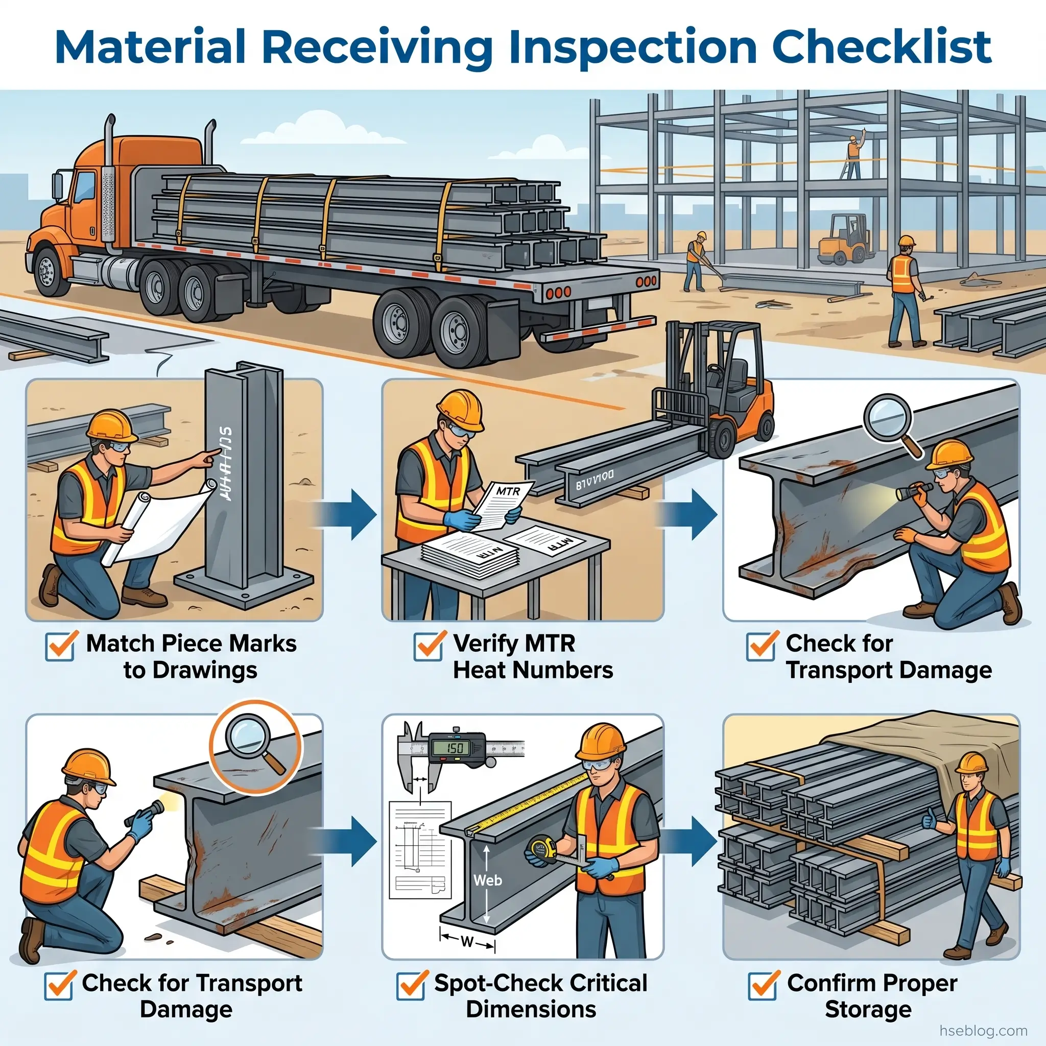
A structured receiving inspection follows this sequence:
- Reconcile the delivery against erection drawings — match piece marks, quantities, and member sizes to the bill of materials and erection plan.
- Verify Mill Test Reports (MTRs) — cross-reference heat numbers on physical members against the MTR to confirm steel grade compliance (ASTM A992, A572, or A36 in US projects; S235, S275, or S355 under Eurocode).
- Inspect for transport damage — check long slender members for bowing from inadequate transit support, bolt holes for elongation from improper stacking, and cut edges for corrosion bloom.
- Spot-check critical dimensions — measure connection geometry, member lengths, and hole spacing against fabrication drawings.
- Verify surface treatment — confirm coating system, dry film thickness (DFT), and compatibility with specified fireproofing.
- Confirm proper storage — members stacked on dunnage with drainage, coated surfaces protected, fasteners stored dry.
Verifying Mill Test Reports and Material Certificates
An MTR documents the steel’s chemical composition, mechanical properties (yield strength, tensile strength, elongation), and heat number traceability from the producing mill. The inspector’s task is to confirm that the MTR values meet the project specification — not just that an MTR exists.
For projects under EU specifications, EN 10204 defines certificate types with increasing levels of assurance:
- Type 2.1/2.2 — manufacturer’s declaration, no independent testing
- Type 3.1 — inspection by the manufacturer’s authorized representative with test results
- Type 3.2 — inspection and testing witnessed by the purchaser’s representative or an independent body
The practical reading of these distinctions on most projects: if the specification calls for 3.1 certificates and the fabricator provides 2.2 declarations, the material cannot be accepted without an engineering disposition — regardless of whether the steel itself is perfectly adequate.
Identifying Transport Damage and Storage Defects
Transport damage concentrates predictably at specific points. Long members bow when supported at too few points during transit. Bolt holes elongate when members are stacked without dunnage between layers, concentrating load on connection areas.
Visual indicators that trigger rejection or repair evaluation include:
- Plastic deformation — permanent bending, twisting, or kinking beyond the tolerance class
- Corrosion at cut edges — rust bloom where the coating system has been breached
- Coating damage — scratches, gouges, or delamination exposing bare substrate
- Moisture entrapment — water pooling between stacked members, accelerating corrosion
The judgment call between reject and repair depends on the extent and location of damage. A minor coating scratch on a web mid-span is a field-repair item. The same scratch across a faying surface in a slip-critical bolted connection changes the friction coefficient and requires engineering evaluation.
Fabrication Quality Verification Before Erection
AISC 360-22 Chapter N establishes the inspection framework for welded and bolted connections in the US, while EN 1090-2:2018 governs execution requirements across the EU and UK — and they do not use the same tolerance systems. AISC’s dimensional tolerances are defined in the Code of Standard Practice (AISC 303), while EN 1090-2 uses its Table D series. Projects operating under multiple jurisdictions must identify the governing tolerance standard in contract documents before fabrication begins, not during pre-erection inspection.
Fabrication verification covers four categories:
- Dimensional accuracy — member lengths, connection geometry, cope dimensions, and hole patterns checked against fabrication drawings within the applicable tolerance class.
- Weld quality — visual examination as a minimum for all welds; NDT for specific connection types by risk category.
- Connection compliance — bolt hole spacing, group patterns, edge distances, and cope geometry matching the design.
- Surface treatment — coating system, DFT, and system compatibility with fireproofing or other applied finishes.
A pattern worth noting: fabrication shops can produce technically compliant individual pieces where cumulative tolerance stacking across multiple connected members only becomes apparent during erection. Pre-erection fit-up checks on complex connections — particularly moment connections and multi-member nodes — catch these issues before the crane is committed.
Weld Inspection and Non-Destructive Testing Requirements
The April 2025 release of AWS D1.1/D1.1M:2025 (25th edition) introduced enhanced WPS documentation requirements, including mandatory recording of preheat and interpass temperatures, along with the addition of ASTM A913 Grade 80 as a prequalified base metal. Inspectors working to the current code should confirm their acceptance criteria reference Table 8.1 of the 2025 edition.
Visual weld inspection — required for every weld regardless of other NDT — checks for:
- Cracks — surface-breaking cracks of any size are cause for rejection
- Undercut — depth exceeding the limits in AWS D1.1 Table 8.1
- Porosity — scattered or clustered pores beyond acceptance limits
- Incomplete fusion — visible lack of fusion between weld and base metal
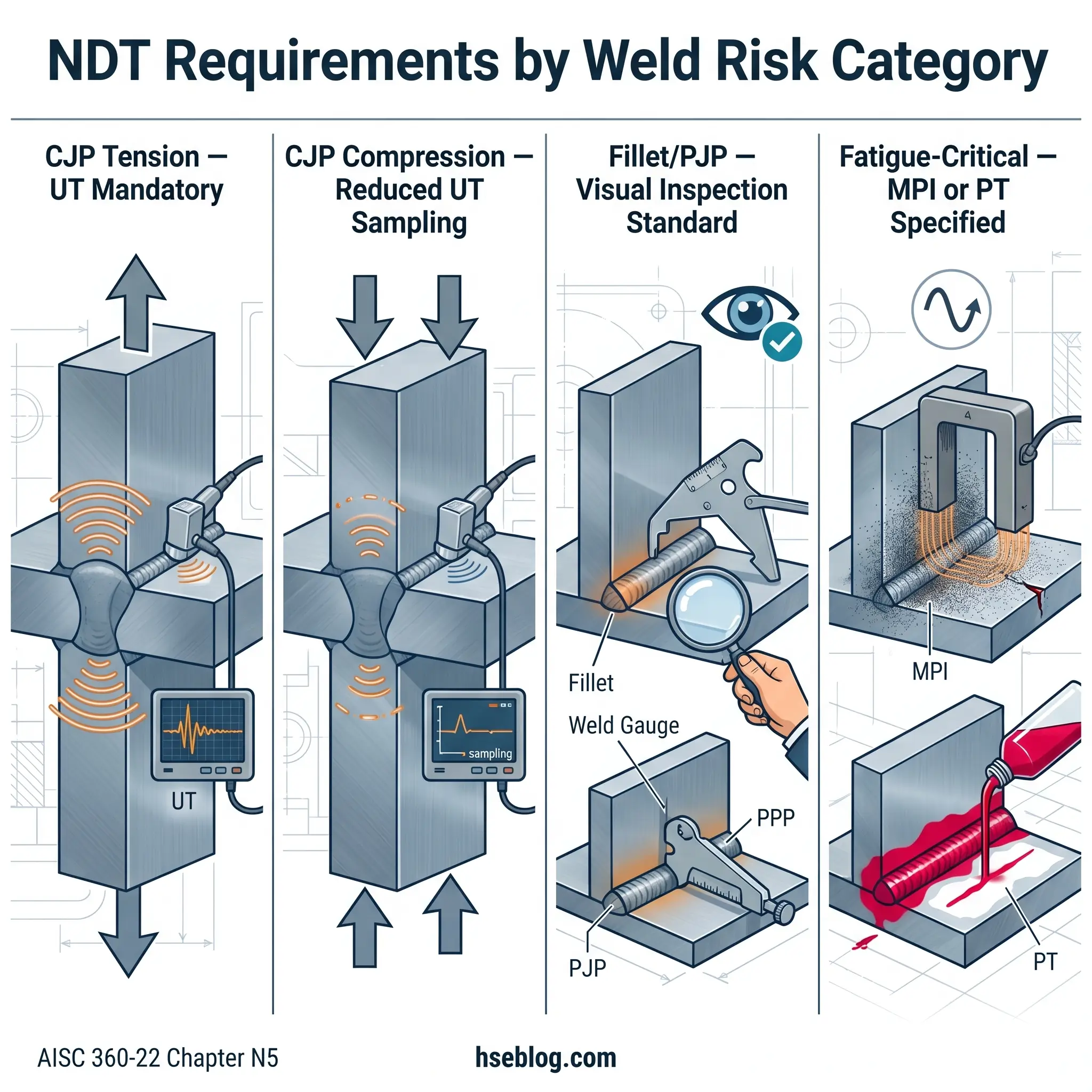
NDT requirements under AISC 360-22 Section N5 are driven by risk category, not applied uniformly:
- CJP (complete joint penetration) groove welds in tension-loaded connections — ultrasonic testing (UT) is mandatory.
- CJP groove welds in compression — reduced UT sampling rates apply.
- Fillet welds and PJP groove welds — visual inspection is typically sufficient unless the project specification or engineer requires additional NDT.
- Fatigue-critical connections — magnetic particle inspection (MPI) or liquid penetrant testing (PT) may be specified regardless of weld type.
Bolt and Fastener Verification
The RCSC Specification for Structural Joints Using High-Strength Bolts (2020 edition, US jurisdiction) requires pre-installation verification testing of bolt/nut/washer assemblies by installation personnel before use in the work. This is not a manufacturer’s certificate review — it is a physical test performed on-site or in the field office using a representative sample from each shipping lot.
Verification before erection confirms that bolt assemblies match the connection design in grade (ASTM A325/F1852 or A490/F2280), diameter, length, and thread configuration. For pretensioned and slip-critical joints, thread length must be verified to ensure thread exclusion from the shear plane where required by design.
Storage matters: high-strength bolt assemblies exposed to moisture lose the lubrication calibration that pre-installation verification testing validated. Assemblies stored unprotected outdoors must be re-tested or replaced.
Site Readiness Assessment Before Steel Erection
The most consequential pre-erection failure mode in the published record is not a missed weld defect — it is proceeding before concrete has achieved adequate cure strength. OSHA’s written-notification requirement under 29 CFR 1926.752(a)(1) exists specifically because inadequate foundation strength has been the root cause of column-base failures and progressive collapses during early erection sequences.
Site readiness assessment covers everything outside the steel itself. It answers one question: is this site physically prepared to safely receive structural steel?
Anchor Bolt and Foundation Inspection
Foundation verification is a hard hold point — not a witness point, not a judgment call. The controlling contractor must provide written notification to the erector confirming two things:
- Concrete has reached 75% of minimum compressive design strength, verified by ASTM standard testing of field-cured samples.
- Any anchor bolt repairs, replacements, or modifications have been approved by the Structural Engineer of Record (SER), per 29 CFR 1926.755(b)(1).
Physical inspection of anchor bolts checks projection height (sufficient thread engagement for nuts and washers), template alignment with column base plate holes, bolt plumb, and grout bed level. OSHA’s steel erection inspection guide details these verification requirements across all erection phases.
Crane, Rigging, and Equipment Readiness
Crane and rigging inspection is a separate discipline from structural steel inspection, but it falls within the pre-erection readiness assessment because erection cannot safely begin without verified lifting equipment. Under 29 CFR 1926.753(c)(2), a qualified rigger must inspect rigging hardware before each shift.
Pre-erection equipment checks include:
- Annual crane certification — current and applicable to the crane configuration planned for the project
- Load chart review — confirming that planned picks (steel member weights at planned radii) fall within the crane’s rated capacity for the specific configuration
- Rigging hardware inspection — slings, shackles, and spreader bars checked for damage, wear, legible capacity markings, and suitability for the load
- Crane operating pad — verified for adequate bearing capacity and level within manufacturer tolerances
Fall protection system readiness — anchor points installed, perimeter control in place, controlled decking zone boundaries marked — must also be confirmed before erection crews ascend. OSHA’s site preparation requirements provide the detailed regulatory framework for this assessment.
How to Build a Pre-Erection Steel Inspection Checklist
The distinction most template-based checklists miss is the difference between hold points and witness points. Treating every inspection as a witness point — where work may proceed without inspector presence — defeats the purpose of pre-erection verification at the stages where failure is irreversible.
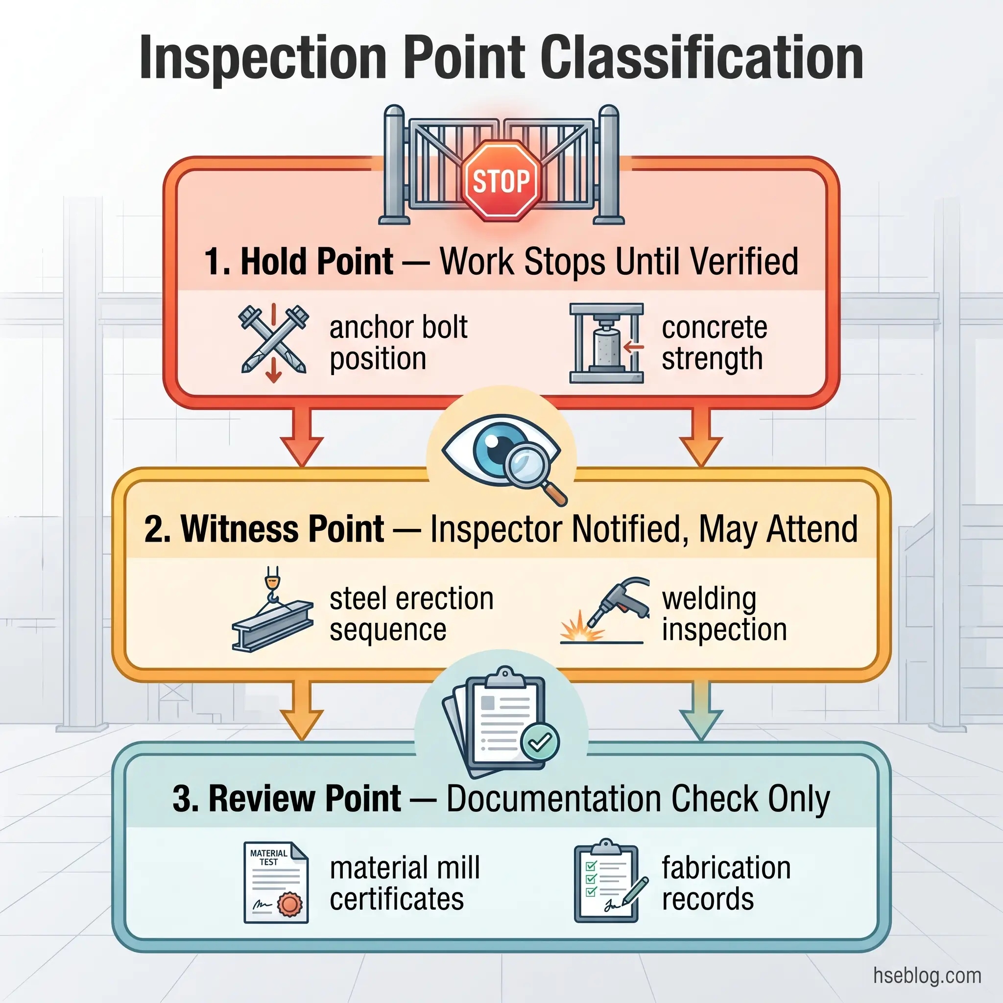
A project-specific checklist is built from the Inspection and Test Plan (ITP), not copied from a generic template. The ITP maps every inspection activity to a construction stage and classifies each as one of three types:
- Hold point (H) — work stops until the inspector verifies and signs off. Anchor bolt position, concrete strength, and CJP groove weld NDT are hold points.
- Witness point (W) — the inspector is notified and may attend, but work can proceed if the inspector does not attend within the notification period.
- Review point (R) — documentation review only; no physical presence required.
Building the Checklist From Standards
The framework for assembling inspection points depends on jurisdiction:
- US projects — AISC 360-22 Chapter N tables list specific QC and QA inspection tasks for bolted connections, welded connections, and steel preparation. These tables are the starting skeleton.
- EU/UK projects — EN 1090-2 Table 24 maps inspection scope to execution class. Higher execution classes (EXC3, EXC4) require progressively more extensive NDT, tighter tolerances, and third-party QA involvement.
Every checklist item should reference its acceptance criteria, the applicable code clause, the responsible party, and the inspection classification (H/W/R). Non-conformance reporting (NCR) and corrective action tracking should be integrated — each checklist item needs a clear pathway for what happens when the answer is “no.”
Digital inspection platforms (SafetyCulture/iAuditor, Procore, PlanGrid) offer real-time reporting, photo documentation, and NCR tracking that paper checklists cannot match. However, the tool does not replace the inspector’s competence — a digital checklist with the wrong hold points is no better than a paper one.
What Are Common Pre-Erection Inspection Failures and How to Prevent Them?
Schedule pressure is the single most reliable predictor of inspection failure during the pre-erection phase. When erection day arrives and steel is on trucks, the practical pressure to “inspect later” overwhelms documented procedures — particularly on projects without clearly enforced hold points.
The published record of OSHA citations and structural failure investigations reveals recurring patterns. A study of 166 steel erection fatalities between 2000 and 2005 found that 125 were caused by falls and 40 by struck-by or crushed-by events (Beavers, Moore, Rinehart & Schriver, ASCE Journal of Construction Engineering and Management, 2006). Many of these proximal causes trace back to pre-erection deficiencies — absent fall protection readiness, unstable site conditions, or inadequate rigging verification.
The BLS Census of Fatal Occupational Injuries for 2024 recorded 1,034 construction fatalities in the US, with structural steel erection maintaining a fatality rate of 15.2 per 100,000 FTE — significantly above the construction-industry average of 9.2 per 100,000 FTE (BLS/Construction Dive, 2026). Falls, slips, and trips alone accounted for 389 of those construction deaths (BLS, 2026).
Each common failure mode follows a predictable cause-and-prevention pattern:
- Proceeding without written concrete-strength verification — sites cited under 29 CFR 1926.752(a) typically show that verbal assurances replaced documented test results. Prevention: enforce the written notification as a non-negotiable hold point in the ITP.
- Accepting transport-damaged steel under schedule pressure — bent members and elongated holes are forced into connections, creating fit-up stress and alignment errors that propagate through the structure. Prevention: receiving inspection occurs on the day of delivery, with documented reject/repair authority.
- Omitting pre-installation verification testing for bolt assemblies — the RCSC requirement is site-performed physical testing, not a review of the manufacturer’s lot certificate. Prevention: designate bolt verification as a hold point; no bolting begins until verification records are complete.
- Skipping NDT on CJP groove welds in tension connections — the most dangerous omission, because these connections carry the highest consequence of failure and visual inspection alone cannot detect sub-surface discontinuities. Prevention: ITP must classify these welds as hold points with UT completion required before erection of connected members.
- Failing to verify SER approval for anchor bolt modifications — 29 CFR 1926.755(b)(1) requires that the controlling contractor notify the erector of any anchor rod repairs, replacements, or modifications approved by the SER. Prevention: document the approval chain with SER sign-off before column erection at affected locations.
Documentation and Record-Keeping for Pre-Erection Inspection
The most useful inspection records are those structured for retrieval under adversarial conditions. If a structural failure triggers an investigation, records that cannot be quickly located and cross-referenced to specific components are functionally equivalent to records that do not exist.
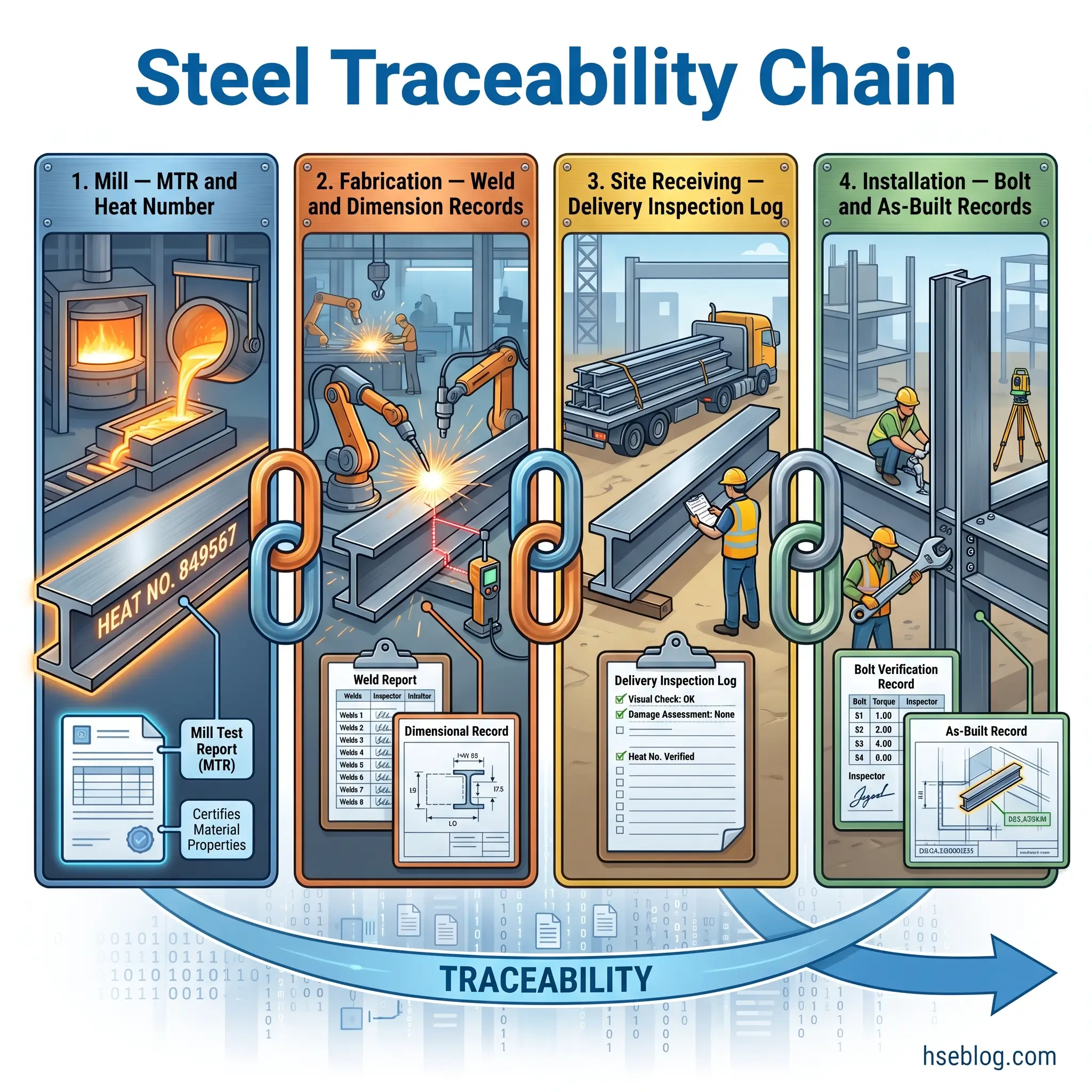
AISC 360-22 Chapter N requires documentation of inspection reports, NDT results, and bolt verification records. The traceability chain runs from the mill test report through fabrication shop inspection, receiving verification, and field installation — each link must be recoverable by component identification.
What Must Be Documented
Every pre-erection inspection phase generates specific records:
- Material receiving — MTR cross-reference log, transport damage reports with photographs, dimensional spot-check records, NCR forms for rejected or repaired components.
- Fabrication verification — weld inspection reports (visual and NDT), dimensional tolerance records, bolt pre-installation verification test results, coating/DFT verification.
- Site readiness — written concrete strength notification, anchor bolt survey records, crane certification copies, rigging inspection logs, fall protection readiness confirmation.
- Non-conformance — each NCR documents the deficiency, engineering disposition (accept-as-is, repair, reject), corrective action taken, and verification of closure.
Photo documentation should follow a standard: each photo tied to a piece mark or location identifier, dated, and showing both the overview context and the close-up detail. Photographs without identifiable references to specific components have limited evidentiary value.
Record retention periods vary by jurisdiction and contract requirements, but the practical standard for structural steel records is the design life of the structure — which effectively means permanent retention for primary structural members.
Frequently Asked Questions
Conclusion
Pre-erected steel inspection fails most often not because inspectors lack technical knowledge, but because the inspection program lacks enforced hold points. The distinction between a hold point and a witness point is the difference between a quality gate that stops defective work and a documentation exercise that records it after the fact.
The three-phase framework — material receiving, fabrication verification, and site readiness — provides the structure. The regulatory anchors are clear: OSHA’s written-notification requirement for concrete strength, AISC 360-22’s QC/QA inspection task lists, AWS D1.1:2025’s weld acceptance criteria, and the RCSC’s pre-installation bolt verification testing. For EU/UK-jurisdiction projects, EN 1090-2’s execution class system scales inspection scope to consequence.
Ask this question of your current pre-erection steel inspection program: which of your inspection points are genuine hold points — where erection physically cannot proceed without sign-off — and which are witness points that work will proceed past whether the inspector shows up or not? If you cannot answer that clearly for anchor bolt verification, concrete strength, and CJP tension weld NDT, the checklist is a form, not a control.