The main difference between 2-wire and 3-wire circuits is the presence of a third conductor — typically an equipment grounding conductor (ground wire) or an additional hot wire. In a 2-wire circuit, only a hot and neutral conductor carry current. A 3-wire circuit adds either a ground wire for fault protection or a second hot wire for dual-voltage capability, providing enhanced safety, greater power delivery, or both.
Between 2011 and 2023, contact with electricity killed 1,940 workers in US workplaces alone, and 70% of those fatalities occurred in non-electrical occupations (Electrical Safety Foundation International, 2026). That last figure is the one that should hold your attention. The workers most likely to die from electrical contact are not electricians — they are maintenance technicians, painters, HVAC installers, and general laborers who interact with circuits they do not fully understand.
At the center of that knowledge gap sits one of the most fundamental questions in electrical safety: what is the difference between 2-wire and 3-wire circuits, and why does it matter? The answer determines whether a ground fault trips a breaker in milliseconds or sends current through a human body. This article breaks down both circuit configurations across residential and industrial contexts, maps the grounding and earthing requirements across US, UK, and international standards, and addresses the failure patterns that turn a wiring question into an injury investigation. The primary keyword — difference between 2 wire circuits and 3 wire circuits — points to a deceptively simple question with life-safety consequences.
What Are 2-Wire and 3-Wire Circuits?
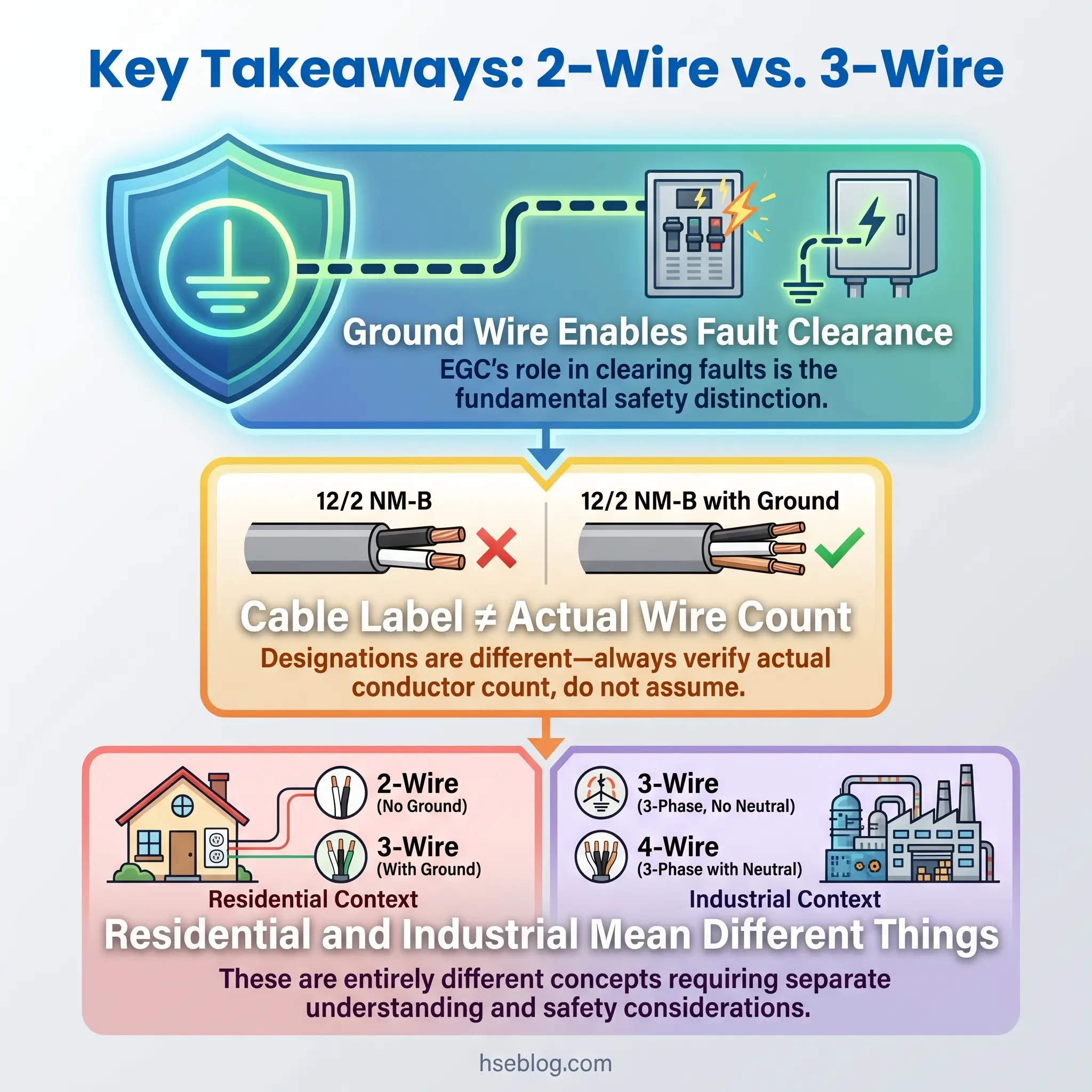
The terms “2-wire” and “3-wire” describe the number of insulated current-carrying conductors inside a cable sheath. This is the definition that matters — and the one that causes the most confusion. A “2-wire” cable such as 12/2 NM-B (US designation) actually contains three physical conductors: one hot, one neutral, and one bare copper equipment grounding conductor. The cable industry does not count the ground wire in its designation. A “3-wire” cable such as 12/3 NM-B contains four physical conductors: two hot, one neutral, and one bare ground.
This naming convention is not a minor technicality. A consistent pattern in electrical incident investigations is that workers assume a “2-wire” cable has no ground path at all, when in modern installations it typically does include a bare equipment grounding conductor (EGC). That assumption leads to skipped testing, improper connections, and the very fault-exposure conditions the EGC exists to prevent.
Watch For: The cable designation and the system description are not the same thing. “2-wire cable” excludes the ground from its count. “2-wire system” may describe an older circuit with genuinely no ground conductor. Always verify the actual conductor count before making safety assumptions.
In its simplest terms:
- 2-wire circuit — one hot (line) conductor and one neutral conductor carry current. Modern cables include a separate EGC; older installations may not.
- 3-wire circuit — two hot conductors plus one neutral (for split-phase / dual-voltage), or one hot plus one neutral plus one dedicated ground. The EGC is present in addition.
The configuration varies by application. In residential wiring, a 3-wire cable supports 240V appliance circuits or 3-way switch arrangements. In industrial motor control, “2-wire” and “3-wire” refer to entirely different control circuit configurations — a distinction covered in detail later in this article.
Conductor Roles: Hot, Neutral, and Ground
Each conductor in a circuit serves a specific electrical function. Conflating them — particularly the neutral and the ground — is one of the most common and dangerous errors in both residential and industrial wiring.
The hot (line) conductor carries current from the source to the load. It is the energized conductor during normal operation and presents the primary shock hazard. In US wiring, it is typically black or red; in UK/IEC systems, brown (line) or grey/black (second/third line in three-phase).
The neutral (grounded conductor) completes the circuit by returning current to the source. It carries current during normal operation and is bonded to ground only at the main service panel. In US wiring, it is white or grey; in UK/IEC systems, blue.
The equipment grounding conductor (EGC) — called the circuit protective conductor (CPC) in UK/IEC terminology — carries no current during normal operation. Its sole purpose is to provide a low-impedance fault current path back to the source if a ground fault occurs, enabling the overcurrent device (breaker or fuse) to trip. In US wiring, it is bare copper or green; in UK/IEC systems, green-and-yellow striped.
The practical reading of the neutral-versus-ground distinction is this: the neutral is a working conductor; the ground is a safety conductor. They perform fundamentally different jobs, and connecting them at any point other than the main service panel creates dangerous conditions — including the “bootleg ground” violation discussed later.
How Do 2-Wire and 3-Wire Circuits Differ?
The differences between two wire and three wire circuits extend beyond conductor count into power delivery, fault protection, and application suitability. A flat comparison misses the operational implications, so each dimension below explains not just what differs but why it matters.
Number and Role of Conductors
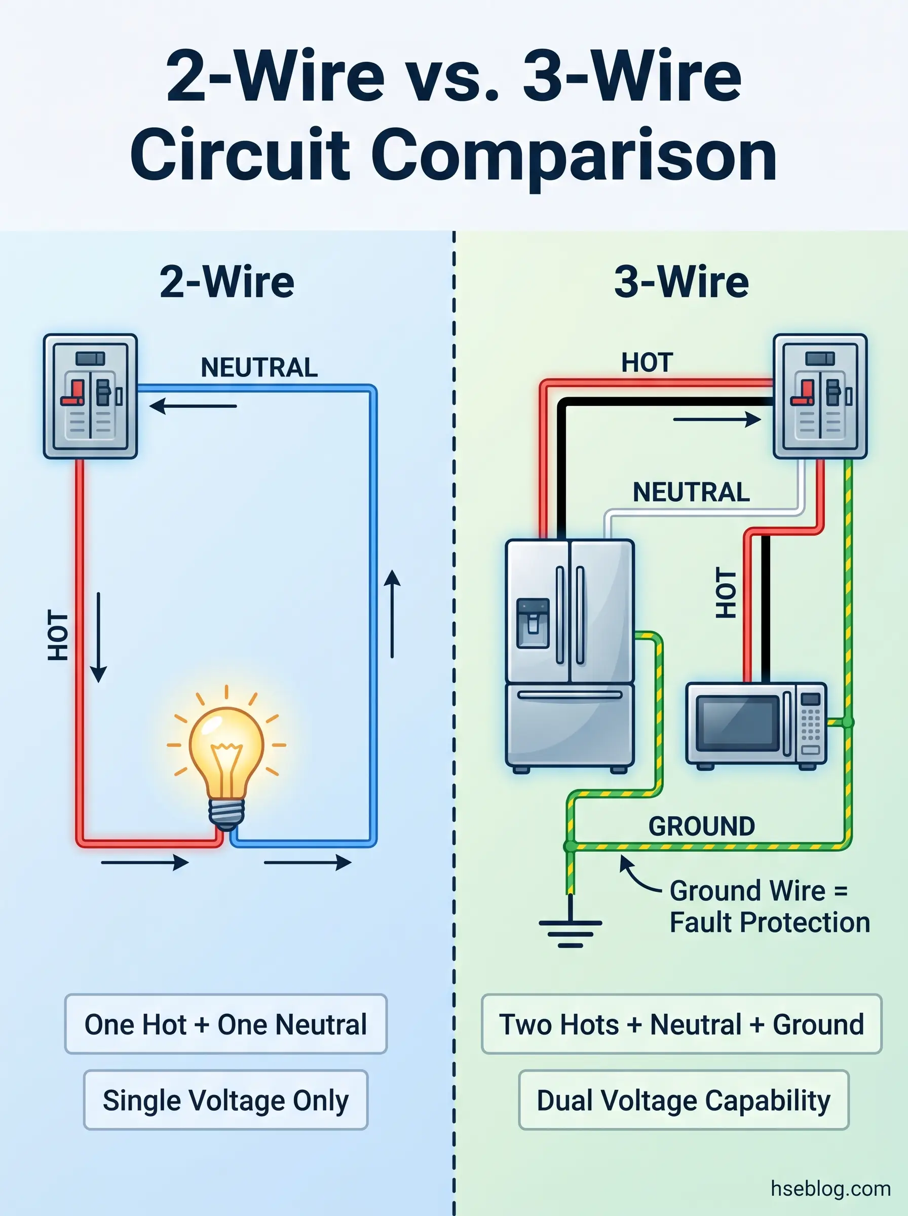
A 2-wire circuit uses one hot and one neutral to deliver single-phase, single-voltage power. A 3-wire circuit adds a second hot conductor (for dual-voltage capability in a split-phase system) or a dedicated ground conductor (in configurations where grounding is counted separately from the cable designation). The practical consequence: a 3-wire split-phase circuit can supply both 120V and 240V from the same cable run, while a 2-wire circuit is limited to a single voltage level.
Power Delivery and Voltage Options
In residential split-phase systems (US, 120/240V), the 3-wire configuration delivers twice the voltage capacity using the same conductor gauge. The two hot conductors are 180° out of phase; voltage measured hot-to-hot is 240V, and hot-to-neutral is 120V. This is how a single cable run supplies a range or dryer with 240V while also powering 120V control circuits within the same appliance.
Ground Fault Protection
This is the critical safety dimension. A circuit with a properly connected EGC provides a deliberate low-impedance path for fault current. When a hot conductor contacts a grounded equipment enclosure, the EGC carries fault current back to the panel at high amperage, tripping the breaker. Without the EGC, the metal enclosure remains energized until someone touches it and completes the fault path through their body to earth — which may not draw enough current to trip the breaker at all.
Voltage Balance and Neutral Loading
A 3-wire multiwire branch circuit (MWBC) shares a single neutral between two hot conductors on opposite phases. When loads are balanced, opposing currents cancel on the neutral, reducing its current. When loads are unbalanced, the neutral carries the difference. The judgment call here is between using an MWBC for efficiency and accepting the risk of an overloaded neutral if breakers are not handle-tied or placed on the same bus phase — a well-documented failure pattern in residential electrical fires.
Installation Complexity and Cost
A 3-wire cable costs more per foot, requires more careful breaker coordination, and demands attention to proper neutral-ground separation. A 2-wire circuit is simpler to install, easier to troubleshoot, and appropriate for basic lighting and receptacle loads. The cost difference is marginal per circuit but scales across a full building installation.
Comparison Table: 2-Wire vs. 3-Wire Circuits
The following table consolidates the core differences for quick reference. Wire color codes are jurisdiction-specific and must not be assumed across borders.
| Feature | 2-Wire Circuit | 3-Wire Circuit |
|---|---|---|
| Insulated Conductors | 1 hot + 1 neutral | 2 hot + 1 neutral (or 1 hot + 1 neutral + 1 ground) |
| EGC Present (Modern Cable) | Yes (bare, not counted in designation) | Yes (bare, not counted in designation) |
| Voltage Options | Single voltage (e.g., 120V or 230V) | Dual voltage (e.g., 120V and 240V) |
| Typical Residential Use | Basic lighting, receptacles | 240V appliances, 3-way switches, MWBCs |
| Industrial Motor Control | Maintained-contact (auto-restart risk) | Momentary-contact with seal-in (restart protection) |
| Hot Wire Colors (US / NEC) | Black | Black + Red |
| Hot Wire Colors (UK / BS 7671) | Brown | Brown + Grey (or Black in older systems) |
| GFCI / RCD Compatible | Yes | Yes |
| Relative Cost | Lower | Higher |
Why Does the Ground Wire Matter for Electrical Safety?
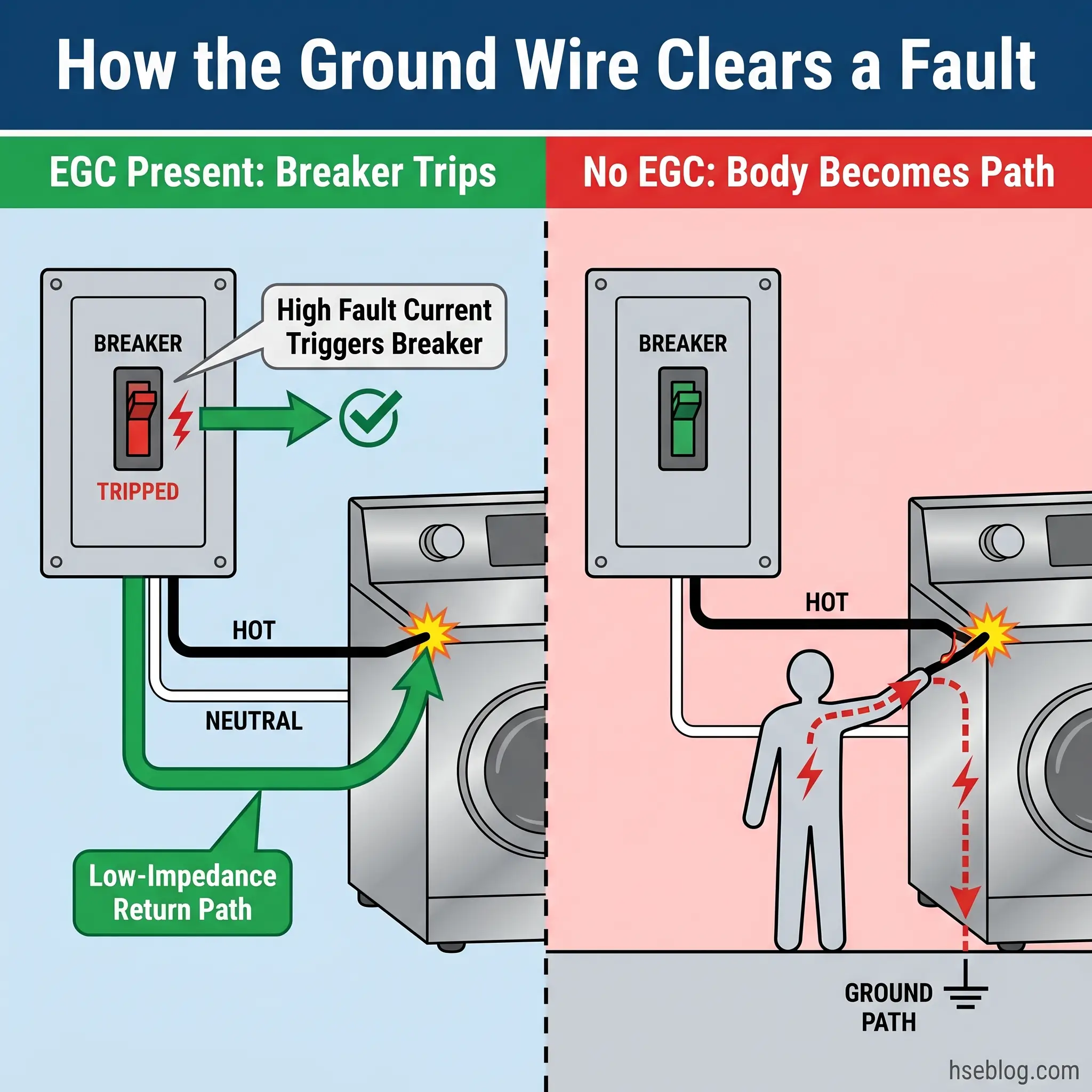
The equipment grounding conductor is the single most important safety feature distinguishing modern wiring from older ungrounded installations. Its function is often described in vague terms — “it provides a path to ground” — but the actual mechanism is more specific and more critical than that description suggests.
During normal operation, the EGC carries zero current. It sits idle inside the cable, connected to every metal enclosure, junction box, and equipment frame on the circuit. The moment a hot conductor contacts a grounded metal surface — a fault — the EGC provides a low-impedance return path for fault current back to the source (the transformer or panel). That low impedance is the key. Fault current through the EGC is high enough — typically hundreds of amps — to trip the overcurrent device (breaker or fuse) within fractions of a second.
Without the EGC, the fault current must find another path. If a person touches the energized enclosure while standing on a conductive surface, their body becomes that path. The resulting current — even at levels below what a standard breaker detects — can be fatal.
One of the most persistent and dangerous misconceptions in electrical work is the belief that a ground rod alone can clear a fault. NEC 250.4(A)(5) (US jurisdiction) explicitly states that the earth shall not be considered an effective ground-fault current path. The resistance of soil is far too high to allow enough current to flow through an earth electrode to trip a standard breaker. Field testing consistently confirms this: fault current through earth alone typically measures in single-digit amps, well below the 15A or 20A trip threshold of a standard residential breaker.
Field Test: Measure the impedance of the EGC path on any circuit. A properly installed equipment grounding conductor will show less than 1 ohm of impedance from the farthest receptacle back to the panel. Compare that with a ground rod’s typical 25-ohm resistance — and the difference between clearing a fault in milliseconds versus leaving an enclosure energized indefinitely becomes obvious.
Ground fault circuit interrupters (GFCIs) and residual current devices (RCDs) provide supplemental protection by detecting current imbalance between hot and neutral — as little as 4–6 mA — and disconnecting within milliseconds. They are a critical second layer. But they do not replace the EGC. A GFCI protects a person from shock; the EGC ensures the breaker clears the fault from the circuit entirely.
ESFI data covering 2023–2024 reported 5,180 non-fatal electrical injuries involving days away from work in the US — a 59% increase from the 2021–2022 period (ESFI, 2026). While not all of these are attributable to grounding deficiencies, the trend reinforces that electrical contact injuries remain a growing workplace concern, and the ground wire’s role in fault clearance is the first line of defense.
Residential vs. Industrial Applications: Where Each Circuit Type Is Used
The phrase “2-wire vs 3-wire” means fundamentally different things depending on whether you are wiring a house or configuring a motor control panel. Competitors treat this as one flat topic. In practice, these are two separate conversations sharing the same terminology, and confusing them has real safety consequences.
Residential Wiring Applications
In residential electrical wiring, the 2-wire and 3-wire distinction maps to cable types and the circuits they serve.
A 2-wire cable (e.g., 14/2 or 12/2 NM-B) is the standard for basic branch circuits: lighting, single-pole switched outlets, and general receptacles. It provides one hot, one neutral, and a bare EGC — adequate for any single-voltage, single-phase load.
A 3-wire cable (e.g., 14/3 or 12/3 NM-B) serves several specific residential applications:
- 3-way and 4-way switch circuits — where two or three switches control a single light fixture. The third insulated conductor (typically red) serves as a traveler between switches.
- 240V appliance circuits — ranges, dryers, water heaters. Two hot conductors on opposite phases deliver 240V hot-to-hot, while the neutral enables 120V for controls and lighting within the appliance.
- Multiwire branch circuits (MWBCs) — two separate 120V circuits sharing a single neutral, fed from opposite bus phases. This saves copper and conduit space but requires handle-tied breakers to ensure both hots disconnect simultaneously.
The MWBC configuration warrants specific caution. If the two hot conductors are placed on the same bus phase instead of opposite phases, the neutral current does not cancel — it doubles. An overloaded neutral on an MWBC is a documented ignition source in residential wiring fires. NEC 210.4(B) (US jurisdiction) requires handle-tied or common-trip breakers for MWBCs specifically to prevent one hot from remaining energized while the neutral is being worked on.
Industrial Motor Control: 2-Wire vs. 3-Wire Control Circuits
In industrial motor control, the “2-wire” and “3-wire” terminology describes control circuit configuration — not power wiring conductors. This distinction is safety-critical and entirely different from the residential meaning.
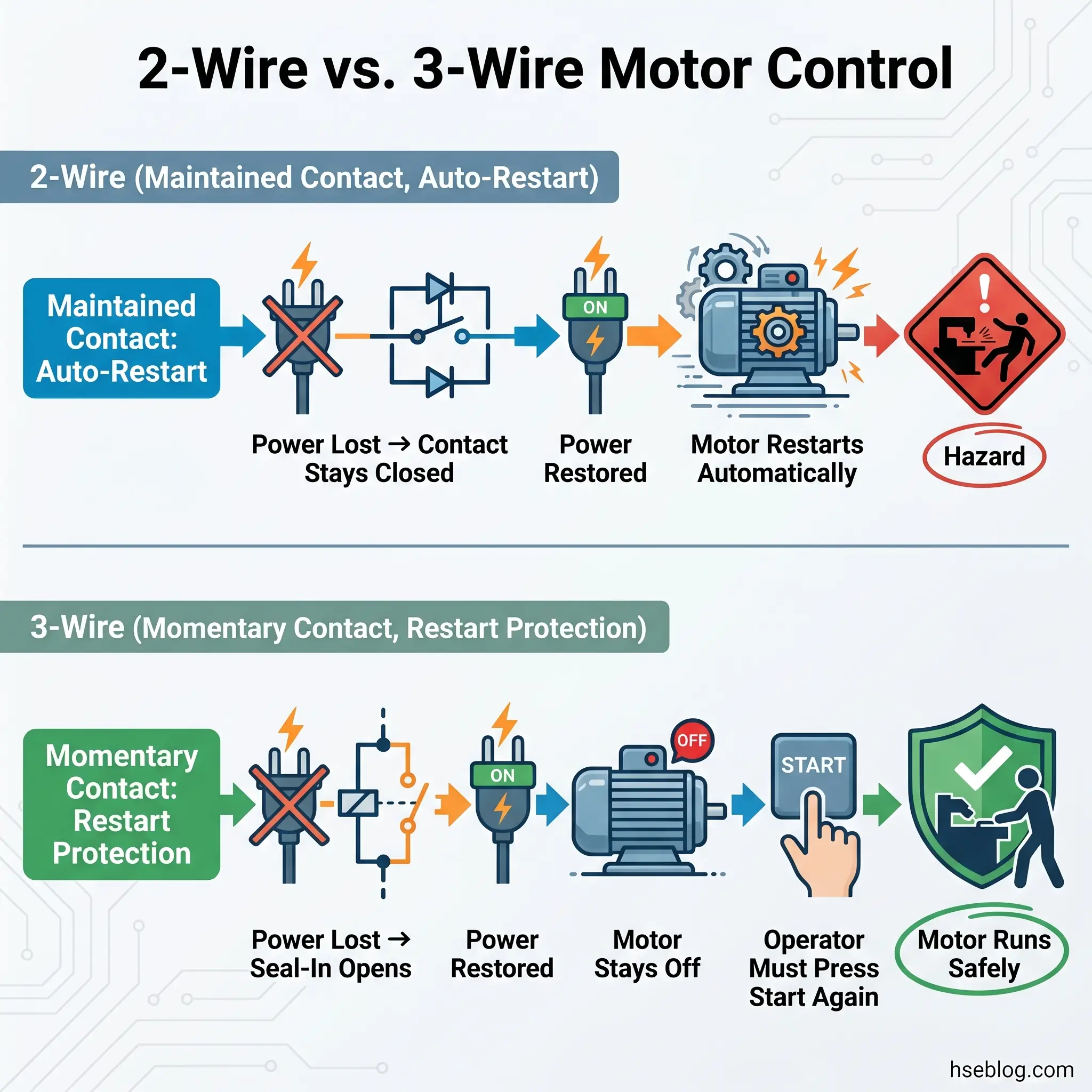
2-wire motor control uses a maintained-contact device — a thermostat, float switch, pressure switch, or selector switch that stays closed as long as the condition persists. When the device closes, the motor runs. When power is lost and restored, the maintained contact is still closed, so the motor restarts automatically. This automatic restart is the hazard. Equipment that restarts unexpectedly after a power outage can cause serious injuries to workers who entered the machine’s danger zone during the outage.
3-wire motor control uses a momentary-contact start button that energizes the motor starter coil. A seal-in (holding) auxiliary contact on the starter maintains the circuit after the start button is released. When power is lost, the coil de-energizes, the seal-in contact opens, and the motor cannot restart when power returns — even though the start button is available. The operator must deliberately press Start again. This is low-voltage protection, and it is the foundation of industrial machine safety.
NFPA 79 Section 7.5 (US jurisdiction, 2024 edition) requires that machinery shall not restart automatically after a power interruption if such restart could create a hazard. This effectively mandates 3-wire motor control for most industrial equipment. OSHA 1910.147 — the lockout/tagout standard — reinforces this by requiring energy isolation procedures that assume equipment will not restart unexpectedly.
Audit Point: When reviewing motor control panels, verify that every motor starter with worker-accessible moving parts uses 3-wire control with a separate start and stop station. Any motor running on 2-wire control (maintained contact, auto-restart) should be evaluated against NFPA 79 Section 7.5 for restart hazard potential.
Earthing and Grounding Systems: How Jurisdictions Handle the Third Wire
The “third wire” concept maps to different earthing arrangements depending on jurisdiction. An HSE professional working across international sites needs to understand not just the wire-count question but how each system handles fault current — because the protective device requirements change accordingly.
US Approach: NEC Article 250
Under NEC Article 250 (US jurisdiction), grounding and bonding are prescriptive. The equipment grounding conductor must be connected to the grounding electrode system at the main service panel. NEC 250.118 lists permitted EGC types — copper or aluminum conductors, rigid metal conduit, electrical metallic tubing, and several others. The system design assumes that the EGC provides the fault return path, and the grounding electrode (rod, plate, concrete-encased electrode) serves primarily to limit voltage from lightning and line surges — not to clear faults.
OSHA 29 CFR 1926.404(f) (US jurisdiction) extends these requirements to construction sites, mandating equipment grounding for cord-and-plug-connected equipment in hazardous locations or systems over 150V to ground. The regulation references OSHA grounding requirements for construction wiring as the enforceable standard.
UK and IEC Approach: Earthing Arrangements
Under BS 7671 IET Wiring Regulations (UK jurisdiction, 18th Edition with Amendment 2: 2022), the earthing type is not chosen by the installer — it is determined by the distribution network operator (DNO) and dictates which protective devices are required. The three main earthing systems are:
- TN-S — separate protective earth (PE) and neutral (N) conductors throughout the system, from the transformer to the installation. The earth path is provided by the supply cable sheath.
- TN-C-S — combined protective earth and neutral (PEN) in the distribution network, separated into PE and N at the installation’s origin. This is the most common arrangement in the UK.
- TT — no earth connection from the supply. The installation has its own earth electrode. RCDs are mandatory on all circuits because the earth fault loop impedance is too high for overcurrent devices to disconnect within required times.
IEC 60364-4-41 (international jurisdiction) defines the performance requirement: automatic disconnection of supply within 0.4 seconds for final circuits up to 32A at 230V in TN systems. TT systems require RCDs because the earth electrode’s resistance makes reliance on overcurrent devices alone impractical.
BS 7671 Amendment 3 (2024) introduced a recommendation for an additional earth electrode for all TN systems — a notable shift toward redundancy in earthing that reflects growing concern about the reliability of PME (protective multiple earthing) connections (IET, 2024).
Terminology Cross-Reference
Many international HSE professionals encounter compliance gaps on multinational project sites because of the terminological mismatch between US and IEC conventions. The following reference maps the key terms:
| US / NEC Term | UK / IEC Term |
|---|---|
| Equipment Grounding Conductor (EGC) | Circuit Protective Conductor (CPC) / PE |
| Grounded Conductor (Neutral) | Neutral (N) |
| Grounding Electrode Conductor | Earthing Conductor |
| Grounding | Earthing |
| Ground Fault Circuit Interrupter (GFCI) | Residual Current Device (RCD) |
| Main Bonding Jumper | Main Earthing Terminal |
The functional safety objective across all jurisdictions is identical: provide a low-impedance fault current path that enables automatic disconnection within a safe time limit. The wire that accomplishes this — whether called EGC, CPC, PE, or “the ground” — is the third wire that distinguishes a protected circuit from an unprotected one.
How to Identify Whether a Circuit Is 2-Wire or 3-Wire
Identifying the wiring configuration of an existing circuit is a practical skill that every HSE professional and maintenance engineer needs, particularly in older buildings where the original installation records are unavailable.
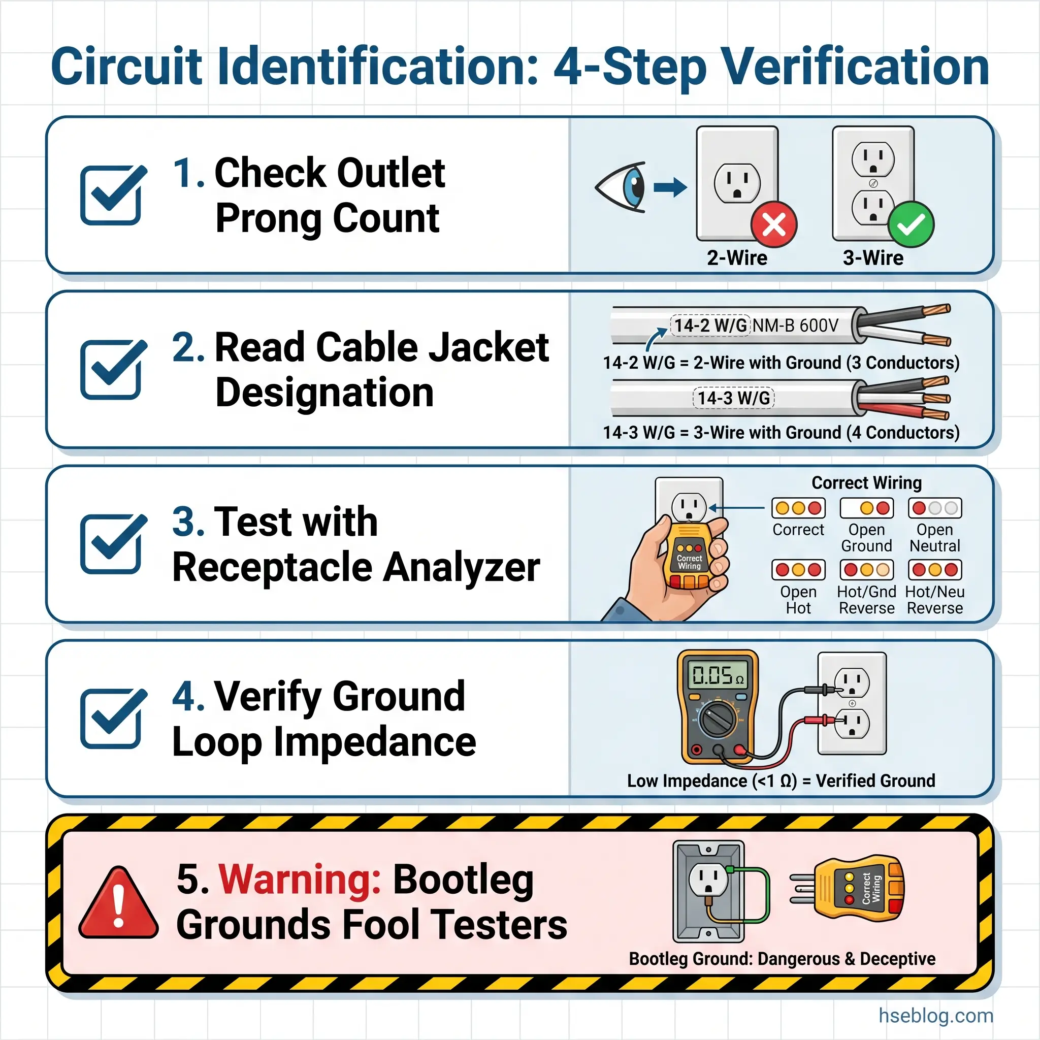
The process follows a logical sequence, starting with visual inspection and moving to instrument verification:
- Check the outlet type. A 2-prong outlet strongly indicates an ungrounded 2-wire circuit, likely installed before the mid-1960s in US construction. A 3-prong outlet suggests grounding is present — but does not guarantee it.
- Read the cable designation. If accessible, the cable jacket is stamped with its configuration. “12/2 NM-B” means 12 AWG, 2 insulated conductors plus a bare ground. “14/3 NM-B” means 14 AWG, 3 insulated conductors plus ground. The number after the slash is the insulated conductor count; the ground is always additional.
- Test with an outlet analyzer. Plug-in receptacle testers can identify open ground, reversed polarity, open neutral, and some types of bootleg ground. However, basic testers have limitations — they may show “correct” on a bootleg ground, which provides no actual fault protection.
- Verify with an impedance tester. For definitive confirmation, measure the ground fault loop impedance. A properly connected EGC will show low impedance from the receptacle ground pin back to the panel. A bootleg ground — where someone connected the ground terminal to the neutral at the receptacle — will show the neutral’s impedance, and will not activate a GFCI during testing because no current imbalance exists.
Watch For: Bootleg grounds are one of the most common and dangerous wiring violations found in older building inspections. A previous owner or unqualified installer replaces a 2-prong outlet with a 3-prong outlet and jumpers the ground terminal to the neutral screw. Basic outlet testers show a false “correct” reading. The outlet appears grounded but provides zero fault protection. During a ground fault, the metal enclosure energizes the neutral wire throughout the circuit — a condition far more dangerous than having no ground at all.
This false sense of safety is why visual inspection alone is never sufficient for electrical safety assessments. Instrument verification is the standard of care.
Can You Upgrade from a 2-Wire System to a 3-Wire System?
Older buildings wired with genuine 2-wire cable — no equipment grounding conductor — present a recognized safety deficiency. Three code-compliant upgrade paths exist, each offering a different balance of protection, cost, and disruption.
Full rewiring with modern cable is the most comprehensive solution. Every branch circuit is replaced with current-specification NM-B cable containing an EGC. This brings the installation to full modern code compliance, provides true equipment grounding on every circuit, and supports GFCI/RCD protection, surge protection, and sensitive electronics. The cost and disruption — opening walls, ceilings, and floors — make this option most practical during major renovations.
Retrofitting a ground conductor is permitted under NEC 250.130(C) (US jurisdiction). A separate ground wire can be run from the receptacle back to the grounding bus in the panel, the grounding electrode conductor, or the grounding electrode itself. The ground wire does not need to follow the same path as the branch circuit conductors. This is a targeted solution — practical for individual circuits where full rewiring is not justified, and it provides genuine equipment grounding.
GFCI receptacle replacement is the most accessible option. NEC 406.4(D)(2) (US jurisdiction) permits replacing non-grounding receptacles with GFCI type on circuits without an EGC. The GFCI detects current imbalance (as little as 4–6 mA between hot and neutral) and disconnects within milliseconds, providing personnel shock protection. However, this does not provide true equipment grounding. The outlet must be labeled “GFCI Protected” and “No Equipment Ground.”
The judgment call between these three paths depends on the building’s use, the loads served, and the budget. The GFCI option is widely misunderstood as making the circuit functionally equivalent to a grounded 3-wire installation. It does not. Surge protectors connected to GFCI-protected but ungrounded outlets cannot function as designed, because the surge protector diverts transient energy to the ground conductor — which does not exist. Sensitive electronics on these circuits remain unprotected against voltage surges.
Pro Tip: When specifying upgrades for a building with ungrounded 2-wire circuits, match the upgrade path to the load. General lighting and receptacles? GFCI replacement is code-compliant and cost-effective. Home office with computing equipment needing surge protection? Retrofit a ground conductor or rewire those specific circuits.
Frequently Asked Questions
Conclusion
The core lesson across every section of this article is that the difference between 2-wire and 3-wire circuits is not about counting wires — it is about understanding what each conductor does during a fault. The equipment grounding conductor does nothing during normal operation. Its entire value activates in the fraction of a second when a hot conductor contacts a metal surface it should not, and a breaker either trips or does not. That is the line between a tripped breaker and a fatality.
The industry consistently gets two things wrong about this topic. First, it treats the cable designation as the conductor count, leading workers to believe a “2-wire” cable has no ground — when modern 12/2 NM-B cable includes an EGC. Second, it collapses the residential wiring question and the industrial motor-control question into a single answer, when they are fundamentally different safety conversations. A 3-wire residential cable delivers dual voltage. A 3-wire motor control circuit prevents unexpected equipment restart. Both matter, but for entirely different reasons.
Whether assessing an older building’s wiring for upgrade, specifying motor control configurations for industrial equipment, or reconciling US grounding terminology with UK/IEC earthing conventions on a multinational project, the question is always the same: does the fault current have a deliberate, low-impedance path back to the source? If the answer is yes, the system can protect people. If not, the next ground fault becomes a gamble on whether someone is standing in the wrong place.