
TL;DR
- If Zs is too high → Fault current drops below the level needed to trip MCBs or fuses within 0.4 seconds, leaving exposed metalwork energized at dangerous touch voltage.
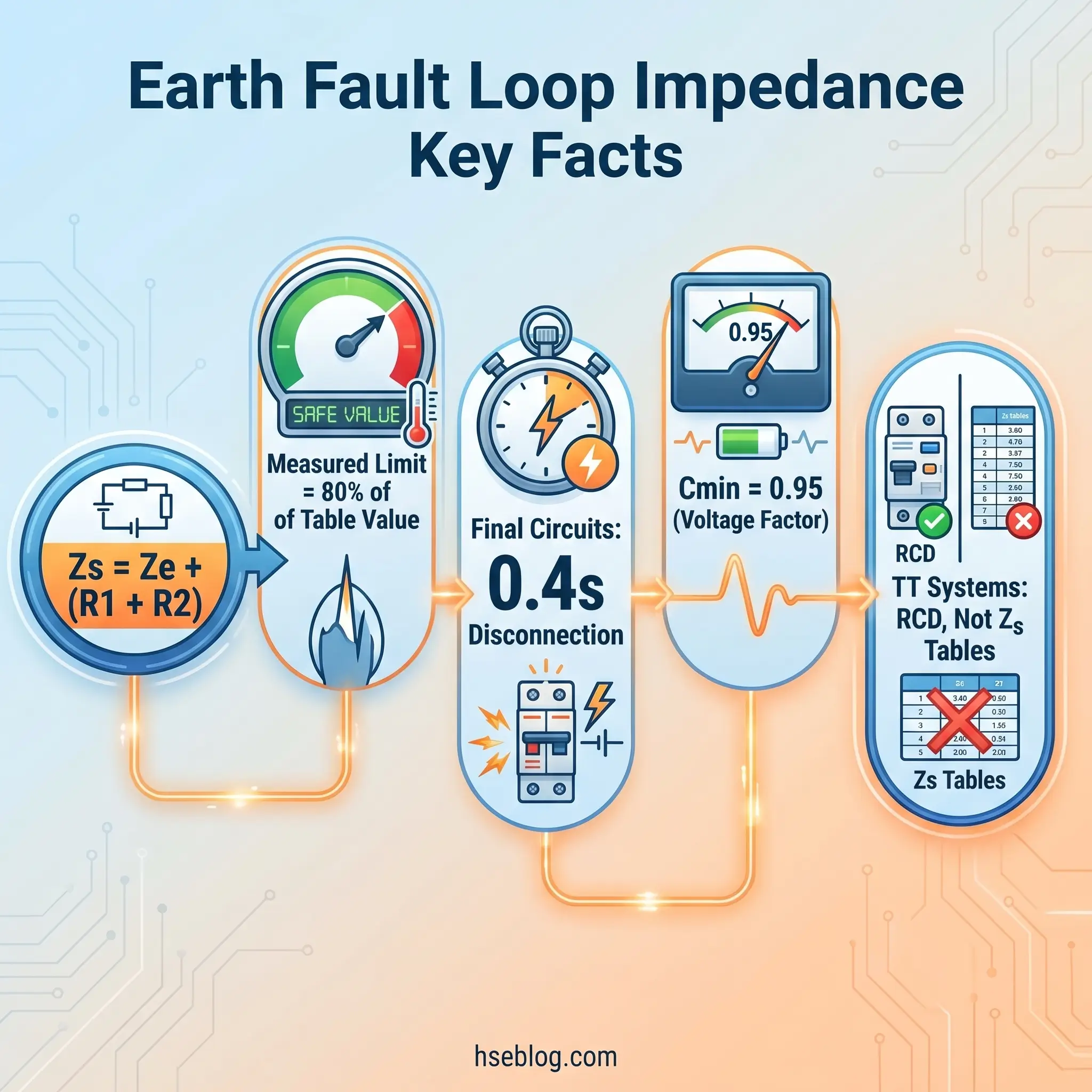
- If you measure Zs at ambient temperature → Compare against 80% of the BS 7671 Chapter 41 table values (UK), not the full tabulated figure — conductor resistance rises approximately 20% at operating temperature.
- If the installation uses a TT earthing system → Overcurrent devices alone cannot achieve the required disconnection times because Ze through the earth electrode is too high. RCD protection is mandatory for automatic disconnection of supply.
- If measured Zs is significantly lower than calculated Zs (Ze + R1+R2) → Suspect parallel earth paths through bonding conductors or metallic service pipes. The true Zs may exceed limits once those paths are removed.
Earth fault loop impedance (Zs) is the total impedance of the complete path that fault current follows when a live conductor contacts earth in an electrical installation — from the supply transformer, through the line conductor to the fault, through the protective earth conductor back to the main earthing terminal, and returning to the transformer neutral. This impedance determines how much fault current flows during a fault: lower impedance produces higher current, causing protective devices to disconnect faster and reducing the risk of electric shock or fire.
What Is Earth Fault Loop Impedance?
Every electrical installation relies on a single protective principle to prevent electrocution during an earth fault: the fault must generate enough current to force the protective device — whether a miniature circuit breaker, fuse, or residual current device — to disconnect the supply before a person touching exposed metalwork receives a lethal shock. The total impedance of the path that fault current travels determines whether this happens fast enough. That total impedance is earth fault loop impedance, abbreviated as Zs.
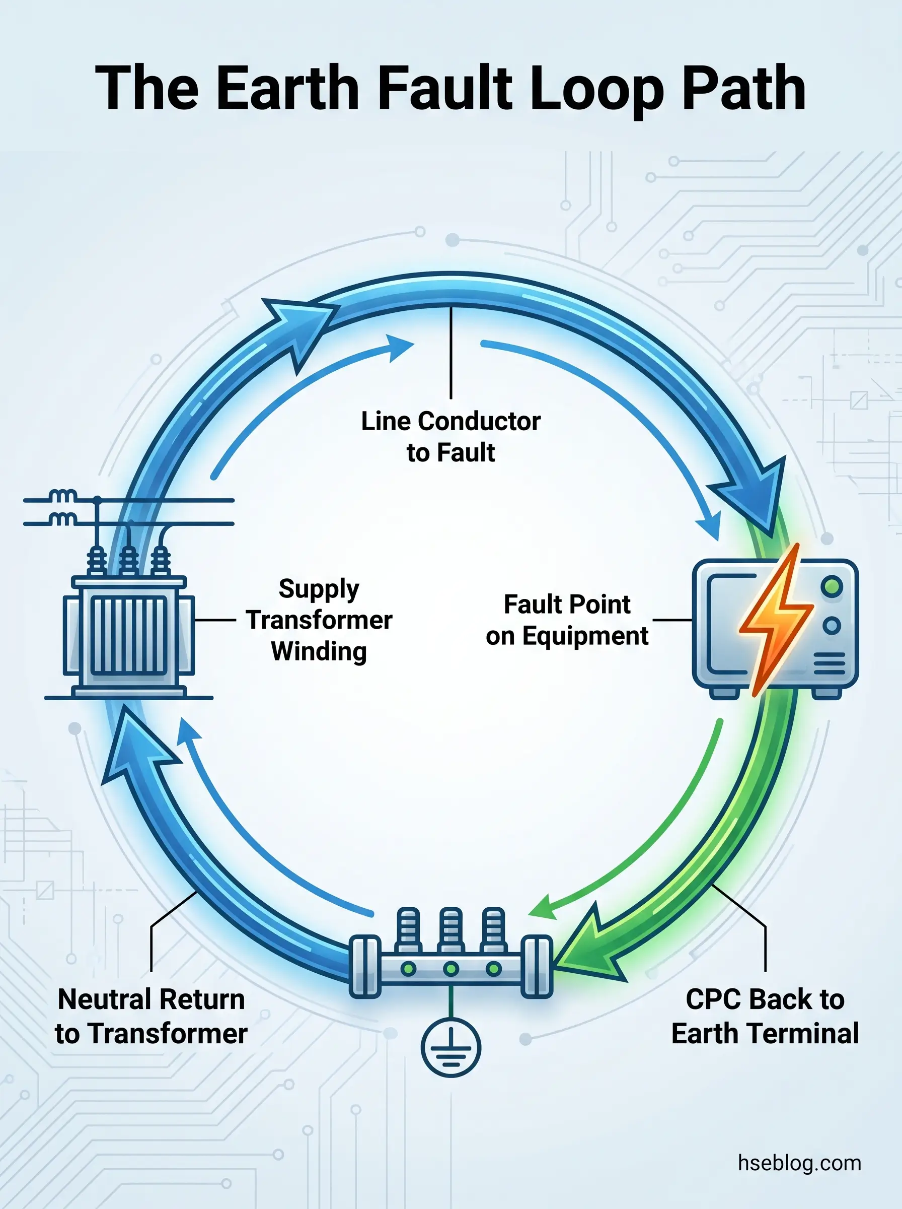
The “loop” is a closed circuit. It starts at the supply transformer’s secondary winding, runs through the line conductor to the point where the fault occurs, passes through the fault itself (typically assumed to have negligible impedance for design purposes), then returns through the circuit protective conductor (CPC) to the main earthing terminal, through the earthing arrangement back to the supply transformer neutral, and finally through the transformer winding to the starting point. Every element in this path contributes resistance and reactance. The total of those contributions is Zs.
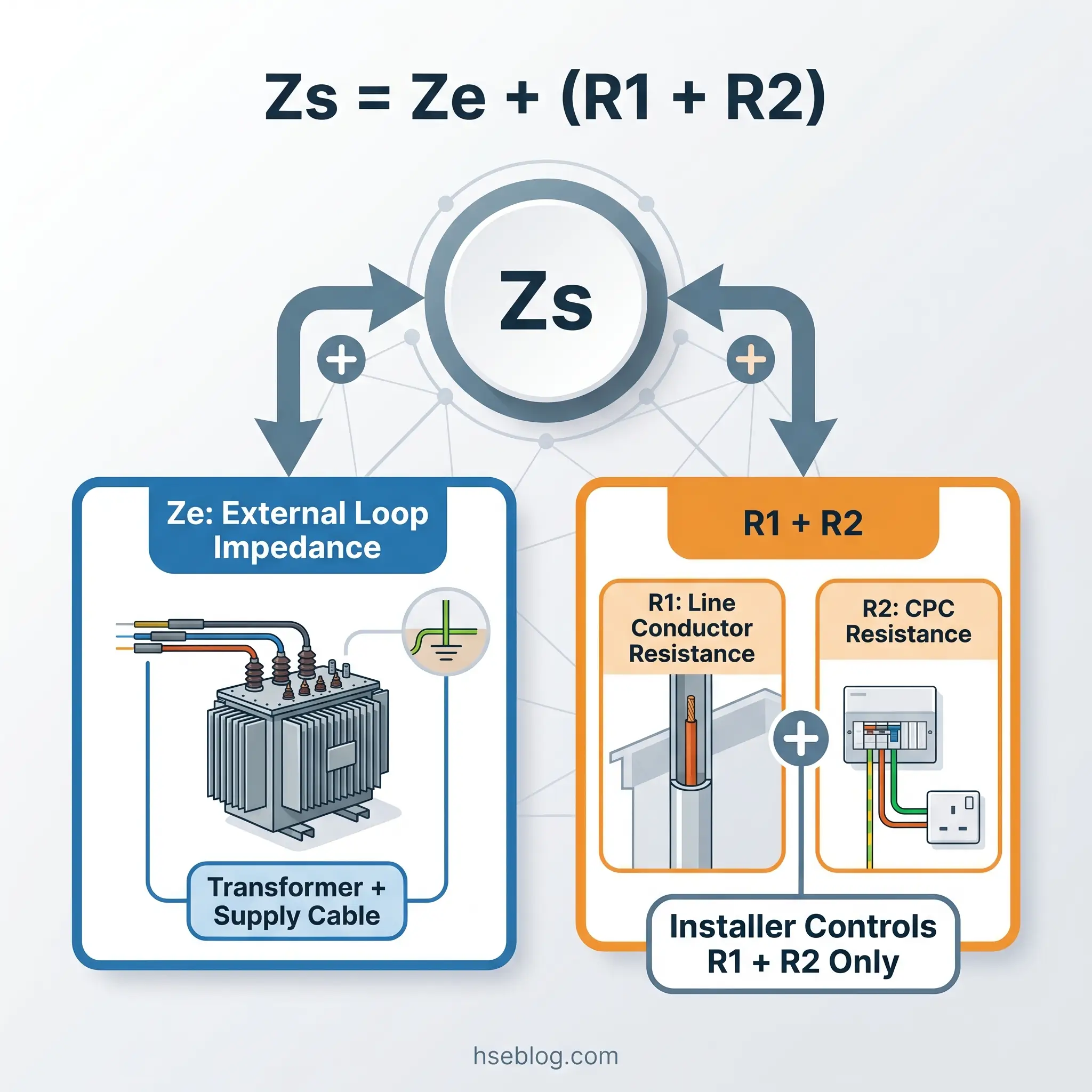
The formula is deceptively simple:
Zs = Ze + (R1 + R2)
Where Ze is the external earth fault loop impedance — everything from the transformer to the installation’s main earthing terminal — and R1 + R2 is the combined resistance of the line conductor (R1) and the circuit protective conductor (R2) for the specific circuit under consideration.
In practice, this concept is frequently reduced to a single number on a test certificate or Electrical Installation Condition Report. But understanding what that number represents — and what makes it rise or fall — is essential for anyone interpreting test results, designing circuits, or assessing whether an installation’s protective measures actually function. A Zs value that passes at ambient temperature during testing may fail under load conditions when conductors are hot, a distinction that catches out even experienced practitioners.
Why Earth Fault Loop Impedance Matters for Electrical Safety
The relationship between loop impedance and safety is governed by Ohm’s law applied to the fault circuit. When a line conductor contacts exposed metalwork, the fault current that flows equals the supply voltage divided by the total loop impedance: If = U₀ / Zs. Higher impedance means lower fault current. Lower fault current means the protective device takes longer to operate — or may not operate at all.
During the time the protective device has not yet tripped, the exposed metalwork remains energized. The voltage appearing on that metalwork — touch voltage — depends on how the supply voltage divides across the loop impedance. A significant portion of the 230V supply can appear on the metalwork, well above the 50V threshold generally considered the upper limit of safe touch voltage under normal conditions. Every millisecond of delay increases the energy delivered through a person’s body if they are in contact with the fault.
The fire risk is equally serious but operates on a different timescale. A fault current too low to trip the overcurrent device but high enough to generate heat in a poor connection or undersized conductor can persist indefinitely. This sustained thermal dissipation is precisely the mechanism behind many electrical distribution fires. Electrical distribution faults were the single largest identifiable cause of workplace fires in the UK, responsible for approximately 18% of all workplace fires — roughly 2,126 incidents out of 6,665 total in 2024/25 (MHCLG, 2025). In domestic settings, approximately 14,186 accidental dwelling fires of electrical origin occur per year in England, representing 53.4% of all accidental dwelling fires (Electrical Safety First, 2024).
The legal framework reinforces why this matters. Under the Electricity at Work Regulations 1989, Regulation 8 (UK), employers must ensure that earthing or other suitable precautions prevent danger when conductors become charged due to a fault — and that earthing conductors have sufficient strength and current-carrying capability. Earth fault loop impedance verification is the primary means of confirming this duty is met.
Watch For: Circuits with borderline Zs values frequently coincide with undersized or deteriorated CPCs. The protective earth conductor is the weakest link in most domestic installations and the component most likely to degrade over time through corrosion, mechanical damage, or poor termination. A passing Zs reading today is not a guarantee of continued compliance.
Components of the Earth Fault Loop
Breaking the loop into its individual elements makes clear which factors the installer controls and which are fixed by the supply network. The fault current path, traced sequentially, passes through these components:
- Supply transformer secondary winding — contributes a small but fixed impedance determined by the transformer’s design and rating. This is outside the installer’s influence entirely.
- Line conductor from transformer to the fault point — includes the distributor’s service cable and the installation’s line conductor to the point of use. The external portion is fixed; the internal portion depends on cable size and length chosen by the installer.
- Fault itself — the point where the line conductor contacts exposed metalwork. For design and calculation purposes, fault impedance is assumed to be negligible (a bolted fault).
- Circuit protective conductor (CPC) — carries fault current from the fault point back to the main earthing terminal. This is the element most directly under the installer’s control and the one most commonly responsible for high Zs readings.
- Main earthing conductor and earthing arrangement — connects the installation’s main earthing terminal to the means of earthing, whether that is a supply-provided earth (TN systems) or a consumer’s earth electrode (TT systems).
- Return path to the transformer neutral — in TN systems, this is the supply neutral or combined PEN conductor; in TT systems, this path passes through the general mass of earth, which introduces substantially higher impedance.
Of all these elements, cable cross-sectional area and circuit length are the only factors the installer can practically change if Zs exceeds limits at the design stage. Transformer impedance, supply cable characteristics, and the external earth path are supply-side properties determined by the distribution network operator.
External Earth Fault Loop Impedance (Ze)
Ze represents everything outside the installation — the impedance of the fault loop from the supply transformer to the main earthing terminal, measured at the origin of the installation with the installation’s main earthing disconnected.
This value is determined by the supply network and the earthing system type. Distribution network operators declare maximum Ze values that designers and testers use as reference. Under the ENA Engineering Recommendation P23 revision (UK), typical declared maximum values are 0.35 Ω for TN-C-S (PME) supplies and 0.8 Ω for TN-S supplies. These are conservative design figures — actual measured Ze is usually lower, but the declared values ensure designs remain compliant even under worst-case supply conditions.
For TT earthing systems, Ze is fundamentally different. The return path passes through the consumer’s earth electrode and the general mass of earth, producing Ze values that can range from a few ohms to several hundred ohms depending on soil conditions, electrode type, and moisture content. This high Ze is why TT systems require a fundamentally different protection strategy.
Ze must be measured during both initial verification and periodic inspection. The test is conducted with the main switch open and the means of earthing disconnected from the installation’s main earthing terminal, using a loop impedance tester connected at the incoming supply side.
Internal Circuit Impedance (R1 + R2)
R1 + R2 is the combined resistance of the line conductor (R1) and circuit protective conductor (R2) for the specific circuit being tested. This is the element under direct installer control through cable selection, routing, and installation quality.
The values depend on three factors: conductor material (copper has lower resistivity than aluminium), cross-sectional area (larger conductors have lower resistance), and circuit length (longer runs mean higher resistance). Published resistance tables — such as those in the IET On-Site Guide (UK) — give resistance per metre for standard conductor combinations, allowing R1 + R2 to be calculated at the design stage.
A critical detail frequently overlooked is the temperature effect. Conductor resistance increases with temperature. At maximum operating temperature for PVC-insulated cables (70°C), resistance is approximately 20% higher than at the ambient temperature (20°C) at which testing is performed. This is not a trivial difference — it is the reason that field-measured values must be compared against adjusted limits rather than the raw tabulated Zs figures in BS 7671 Chapter 41.
R1 + R2 is measured during continuity testing at the furthest point of the circuit, with the circuit isolated and the line and CPC temporarily linked at the distribution board.
How Earth Fault Loop Impedance Varies by Earthing System
The earthing system type is the single biggest determinant of the protection strategy an installation requires. The fault current return path — and therefore the loop impedance and the type of protective device that can achieve automatic disconnection of supply — differs fundamentally between TN-S, TN-C-S, and TT systems. Applying the wrong Zs table to the wrong earthing system is one of the most common errors encountered on inspection reports, and it leads to either false failures or, worse, false passes.
The following comparison summarizes the key differences:
| Earthing System | Typical Ze Range | Primary ADS Protection | Loop Impedance Significance |
|---|---|---|---|
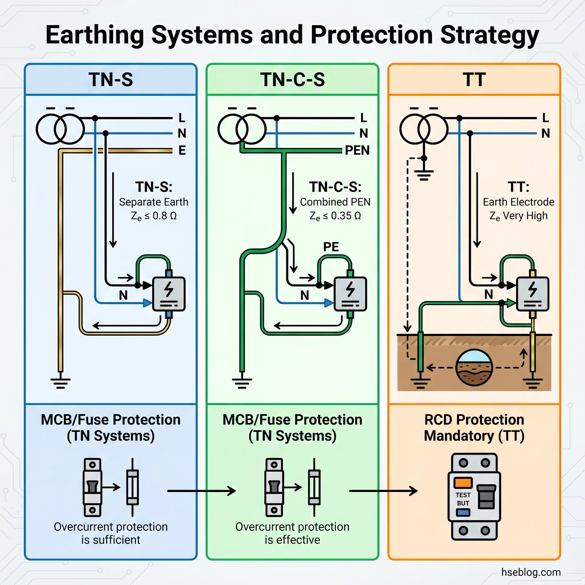
| TN-S (separate earth) | Up to 0.8 Ω (ENA ER P23, UK) | Overcurrent devices (MCBs, fuses) | Moderate Ze; Zs tables for overcurrent devices apply directly |
| TN-C-S / PME (combined PEN) | Up to 0.35 Ω (ENA ER P23, UK) | Overcurrent devices (MCBs, fuses) | Lowest Ze; fastest disconnection by overcurrent devices; but carries broken-PEN conductor risk |
| TT (consumer earth electrode) | Typically 2 Ω to 200+ Ω | RCDs (mandatory for ADS) | Very high Ze; overcurrent devices cannot meet disconnection times; compliance condition is RA × IΔn ≤ 50V |
| IT (isolated or impedance-earthed) | Not applicable in same way | Insulation monitoring; ADS on second fault | First fault does not require disconnection; loop impedance is not the primary protection mechanism |
TN-S systems provide a dedicated protective earth conductor from the supply transformer, separate from the neutral. Ze is moderate and predictable — the earth path has low impedance because it runs through a metallic conductor all the way back to the transformer. Overcurrent protective devices can typically achieve the 0.4-second disconnection time required by BS 7671 Table 41.1 (UK) and IEC 60364-4-41 (International) for final circuits.
TN-C-S (PME) systems use a combined protective earth and neutral (PEN) conductor with multiple earth connections along the supply network. This produces the lowest Ze values — typically 0.35 Ω or less — and therefore the highest prospective fault currents and fastest disconnection times. The trade-off is the broken-PEN risk: if the PEN conductor is severed between the installation and the transformer, the installation loses its earth reference entirely, and dangerous voltages can appear on exposed metalwork and extraneous conductive parts.
TT systems rely on the consumer’s own earth electrode driven into the ground. The return path for fault current passes through the soil, which has far higher resistivity than a metallic conductor. Ze values of tens or hundreds of ohms are common, depending on soil type, moisture, and electrode dimensions. At these impedance levels, overcurrent devices simply cannot draw enough fault current to trip within the required disconnection time. Automatic disconnection of supply in TT systems therefore relies on RCDs, and the compliance condition shifts from a Zs table lookup to the formula RA × IΔn ≤ 50V, where RA is the sum of earth electrode resistance and CPC resistance, and IΔn is the RCD’s rated residual operating current (IEC 60364-4-41, International; BS 7671 Regulation 411.5.3, UK).
Jurisdiction Note: AS/NZS 3000:2018 (Australia/New Zealand) uses MEN (Multiple Earthed Neutral) systems as the standard arrangement, functionally similar to TN-C-S. Clause 8.3 requires earth fault loop impedance verification to confirm protective devices operate within specified disconnection times. The earthing system classification differs in terminology but the underlying physics and protection principles are the same.
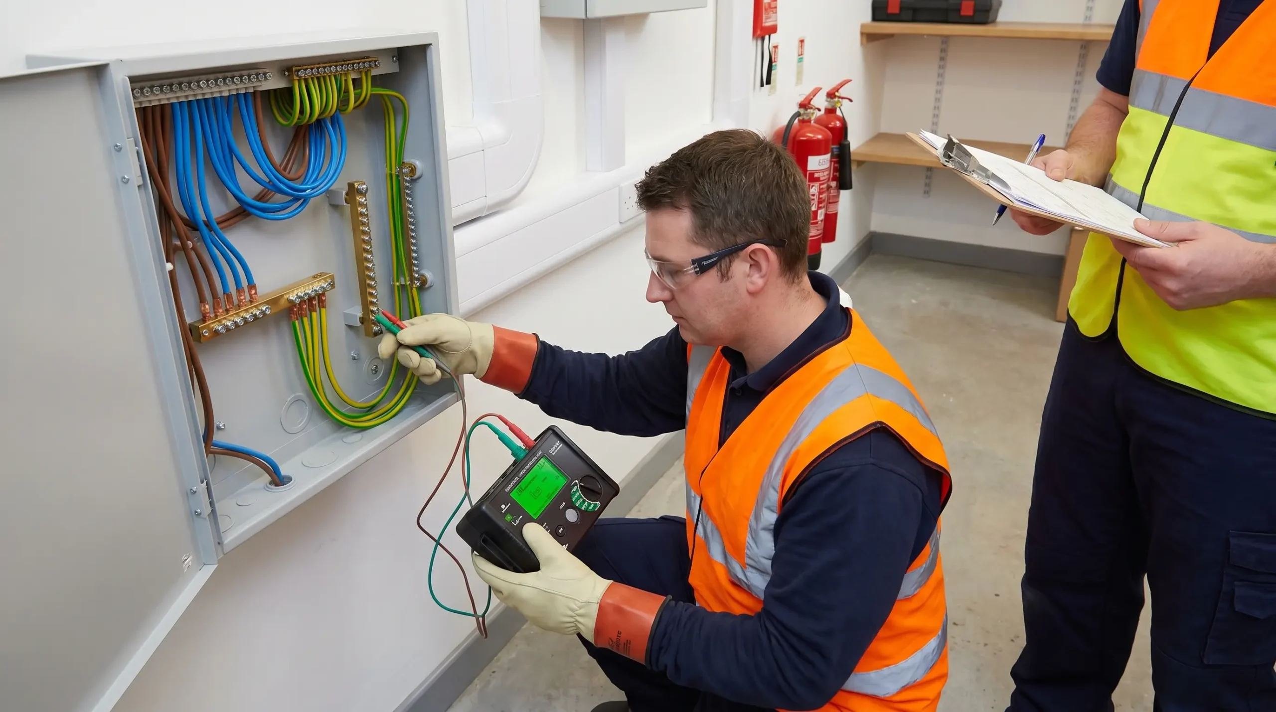
How Is Earth Fault Loop Impedance Measured and Verified?
Two methods exist for determining earth fault loop impedance: direct measurement with a dedicated loop impedance tester, and calculation from separately measured Ze and R1+R2 values. Both are permitted under BS 7671 Regulation 612.9 (UK) and IEC 60364-6 (International). Each method has distinct advantages, and experienced practitioners typically use both and cross-check the results — a significant discrepancy between measured Zs and calculated Zs indicates a problem that needs investigation.
Direct Measurement (Zs Test)
The Zs test is a live test performed at the furthest point of each circuit using an earth fault loop impedance tester. The instrument briefly connects a known resistance between line and earth, measures the voltage drop, and calculates the loop impedance. The process requires the circuit to be energized and the protective devices to remain in service.
Key procedural points for direct Zs measurement:
- Test location — always at the furthest point of the circuit from the distribution board, where R1+R2 is at maximum
- Instrument selection — GS38-compliant test leads are mandatory for live testing (HSE, UK). The instrument must be rated for the prospective fault current at the test location
- RCD-protected circuits — standard loop impedance testers inject enough current to trip a 30 mA RCD. Use a “no-trip” (low-current) loop impedance tester, typically injecting 15 mA or less, for circuits protected by RCDs. Alternatively, use the calculation method
- Recording — record the measured value and compare against the adjusted (80%) maximum permitted Zs for the specific protective device type and rating
Direct Measurement (Ze Test)
The Ze test measures the external earth fault loop impedance at the origin of the installation. The procedure requires the main switch to be opened and the means of earthing to be disconnected from the main earthing terminal — this isolates the installation’s own earthing from the measurement, leaving only the supply-side impedance.
This is a safety-critical step. With the installation’s earth disconnected, all exposed metalwork within the installation temporarily loses its protective earth reference. The test must be completed promptly and the earthing connection restored immediately afterward.
Calculation Method (Zs = Ze + R1+R2)
The calculation method uses separately measured Ze and R1+R2 values. Ze is obtained from the Ze test described above. R1+R2 is obtained during dead-circuit continuity testing at the furthest point of each circuit, with the line and CPC temporarily linked at the distribution board.
This approach is often more reliable than direct Zs measurement for several reasons. It avoids RCD-tripping problems entirely, since R1+R2 is measured on a dead circuit. It eliminates the influence of parallel earth paths — metallic bonding connections and service pipes can provide alternative routes for test current during a live Zs test, artificially reducing the measured value and masking a genuine compliance problem. And it produces more conservative results, which is the appropriate direction for safety-critical measurements.
Audit Point: When reviewing an Electrical Installation Condition Report, check whether the Zs values recorded were measured or calculated. If measured values are significantly lower than what Ze + R1+R2 would predict, parallel earth paths may be providing an artificially low reading. That installation’s compliance may depend on bonding connections or metallic pipes that could be removed or replaced in the future.
The 80% Rule — Temperature Correction
The maximum Zs values tabulated in BS 7671 Chapter 41 (Tables 41.2–41.4, UK) assume conductors at their maximum operating temperature — 70°C for thermoplastic (PVC) insulated cables. Testing is conducted at ambient temperature, typically around 20°C, where conductor resistance is approximately 20% lower.
To account for this difference, field-measured Zs values at ambient temperature must not exceed 80% of the tabulated maximum. The IET On-Site Guide and Guidance Note 3 (UK) publish pre-calculated tables showing these adjusted limits for common protective devices, which is the reference most testers use in the field. The Electrical Safety First maximum earth fault loop impedance table provides another widely used reference for 80%-adjusted measured limits.
A persistent source of confusion arises from practitioners mixing up the “design” Zs values in BS 7671 Chapter 41 with the “measured” Zs limits in the IET On-Site Guide. They are not the same number. The design values are higher because they already assume hot conductors. The measured limits are 80% of the design values because they assume conductors are tested cold. Using the wrong column against a measured value — in either direction — produces incorrect compliance judgements. An IET Wiring Matters article published in May 2024 specifically addressed this confusion, explaining the role of conductor operating temperature in creating the discrepancy between design-stage and measured values.
Maximum Earth Fault Loop Impedance Values and Disconnection Times
Maximum permitted Zs values are not arbitrary. They are calculated from three inputs: the required disconnection time, the operating characteristics of the specific protective device, and the minimum expected supply voltage.
The required disconnection times, per BS 7671 Table 41.1 (UK) and IEC 60364-4-41 (International), are 0.4 seconds for final circuits supplying socket outlets, portable equipment, and circuits in bathrooms or swimming pool zones, and 5 seconds for distribution circuits. These times represent the maximum duration that exposed metalwork may remain energized during a fault before the protective device must disconnect.
The formula linking these elements is:
Zs ≤ (Cmin × U₀) / Ia
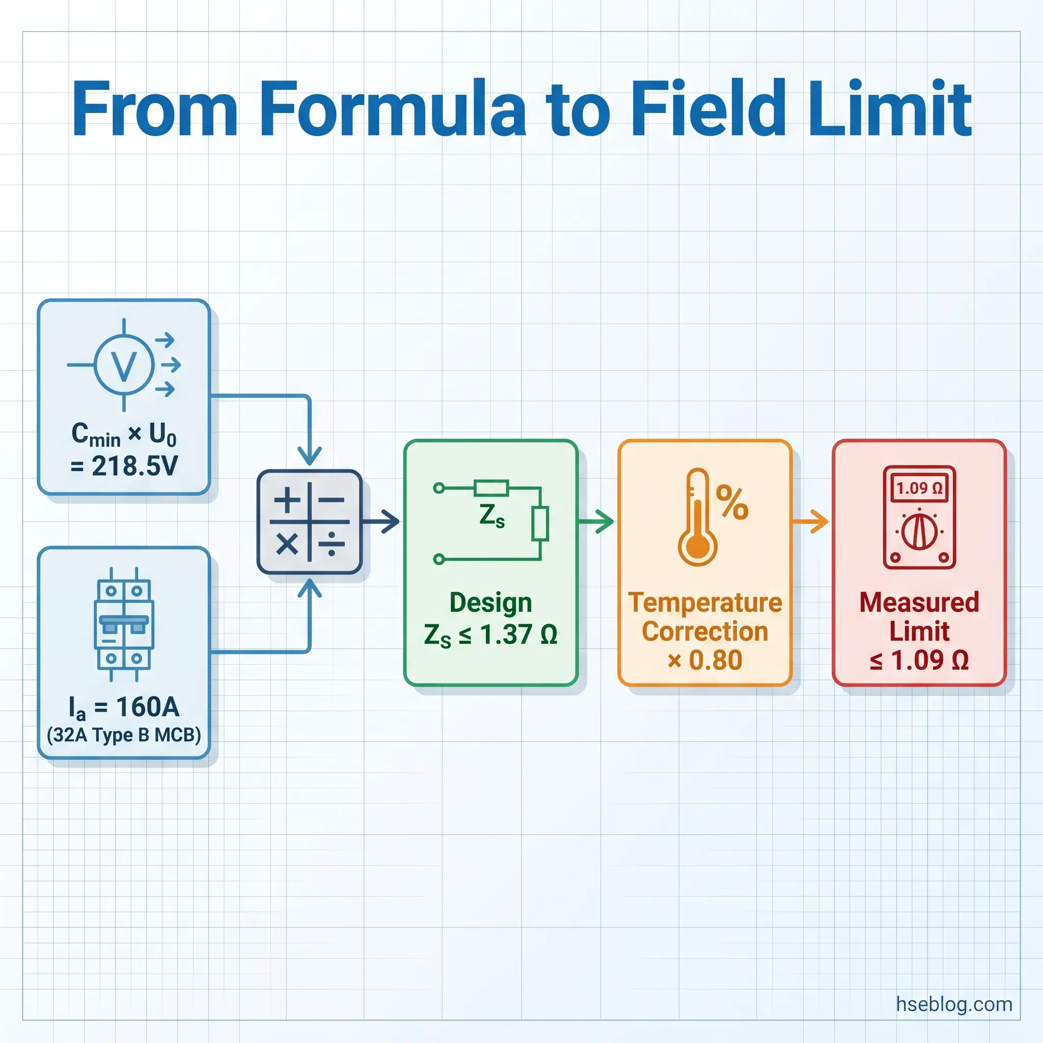
Where Cmin is the minimum voltage factor (0.95 for UK supplies, accounting for up to 5% below-nominal supply voltage), U₀ is the nominal line-to-earth voltage (230V), and Ia is the current required to cause the protective device to operate within the required disconnection time.
The Cmin factor of 0.95 was introduced in BS 7671 Amendment 3 (UK) to reflect the reality that supply voltage is not always exactly 230V. Under worst-case conditions, the supply may be 5% low — meaning only 218.5V is available to drive fault current through the loop. This reduced the maximum permissible Zs values compared to earlier editions of the standard, and installations that previously had adequate margins may now be borderline.
Worked Example: 32A Type B MCB
A common domestic circuit uses a 32A Type B MCB protecting a ring final circuit. For a Type B MCB, the instantaneous magnetic trip operates at 3 to 5 times the rated current. For disconnection within 0.4 seconds, the trip current Ia is 5 × 32A = 160A.
Applying the formula: Zs ≤ (0.95 × 230) / 160 = 218.5 / 160 = 1.37 Ω (design value at maximum conductor operating temperature).
The 80%-adjusted measured limit at ambient temperature: 1.37 × 0.80 = 1.09 Ω.
Any field-measured Zs above 1.09 Ω for this circuit indicates non-compliance and requires investigation — either the circuit is too long, the CPC is undersized, connections are degraded, or the external impedance Ze is higher than expected.
Common Causes of High Earth Fault Loop Impedance
When Zs exceeds the permissible limit for a circuit’s protective device, the root cause falls into a limited number of categories. Identifying which one applies determines the remediation strategy.
Excessive circuit length is the most straightforward cause, particularly in new installations. Every additional metre of cable adds resistance to both R1 and R2. A ring final circuit with an excessively long run, or a radial circuit extended beyond the cable’s capacity for its cross-sectional area, will push R1+R2 above the margin available after accounting for Ze. The fix is either increasing the cable cross-sectional area or reducing the circuit length — both of which are far easier to address at the design stage than after installation.
Undersized CPC is the dominant factor in older installations. Earlier editions of the wiring regulations permitted reduced CPC sizes that are no longer adequate when assessed against current Zs requirements. A 1.0 mm² CPC paired with 2.5 mm² line conductors — common in pre-2000 domestic installations — contributes disproportionately high R2 values on long runs. The CPC resistance is the single largest contributor to R1+R2 in most circuits.
Poor connections degrade impedance progressively. Loose terminals at distribution boards, corroded earth clamps at the main earthing terminal, or deteriorated connections within accessories all add resistance to the loop. These faults are insidious because they may not be visible during a visual inspection, and the additional resistance they contribute can be enough to push a borderline circuit into non-compliance.
High Ze from the supply is outside the installer’s control but must be accounted for. Rural areas served by long overhead line runs, or aged TN-S supplies with deteriorated lead sheath earths, can present Ze values well above the declared maximums. When Ze consumes most of the available impedance budget, very little margin remains for R1+R2, forcing either shorter circuits or larger conductors.
Parallel earth paths present the opposite problem — not a high reading, but an artificially low one. Bonding conductors to metallic gas and water pipes, and the pipes themselves, provide alternative routes for test current during a live Zs measurement. The measured Zs appears acceptable, but the true Zs — through only the intended CPC — may exceed limits. If those metallic services are later replaced with plastic (increasingly common for gas and water), the parallel path disappears and the installation’s actual Zs is revealed. This is one of the strongest arguments for using the calculation method (Ze + R1+R2) as the primary compliance check, since it measures only the intended earth path.
The Fix That Works: When investigating a high Zs reading, start with R1+R2 continuity at the furthest point. If R1+R2 is within expected values for the cable type and length, the problem is in Ze — contact the DNO. If R1+R2 is high, work backward through the circuit checking connections, joint boxes, and CPC continuity until the resistance anomaly is located.
Earth Fault Loop Impedance in EV Charging and Renewable Energy Installations
BS 7671:2018+A4:2026 — published on 15 April 2026, the latest consolidated amendment to the UK national wiring regulations — introduces new requirements for stationary secondary battery installations and functional earthing for ICT systems. While the core Chapter 41 Zs tables remain largely unchanged, the growing prevalence of EV charging circuits and battery energy storage systems creates new practical challenges for maintaining compliant loop impedance values.
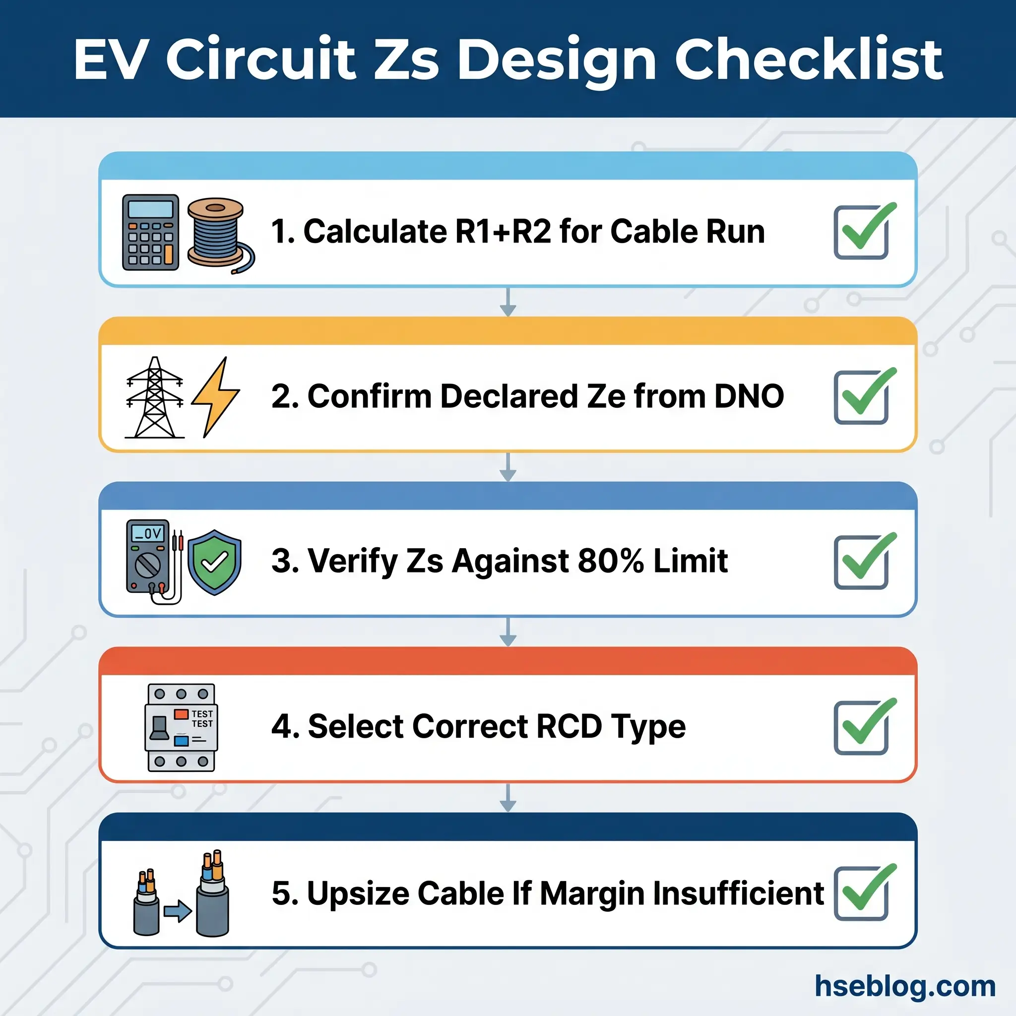
EV charging installations are one of the fastest-growing sources of marginal or non-compliant Zs readings in domestic electrical work. The reason is straightforward: outdoor charge points are frequently installed in detached garages, driveways, or at the boundary of a property, requiring long cable runs from the consumer unit. A 30-metre cable run of 6 mm² twin-and-earth to a 32A Type A or Type B RCD-protected radial circuit can push R1+R2 to the point where Zs exceeds the 80%-adjusted limit for the protective device.
The judgment call for designers and installers is whether to upsize the cable at the design stage — accepting higher material cost — or to discover the problem during commissioning tests when rework is far more expensive. Calculating Zs at the design stage, using published R1+R2 per-metre values for the intended cable and the declared Ze for the supply, avoids this trap entirely. An installation that cannot demonstrate compliant Zs before cabling begins will not pass verification afterward.
RCD type selection adds another layer. EV chargers with onboard DC components may require Type A, Type F, or Type B RCDs depending on the charger’s fault current characteristics. While RCD type does not directly change the Zs calculation, the interaction between RCD sensitivity, cable impedance, and protective device coordination needs to be considered holistically at the design stage.
The previous version of BS 7671 (BS 7671:2018+A2:2022+A3:2024) will be withdrawn on 15 October 2026. Installations designed and certified under the earlier edition must still demonstrate compliant Zs values, but practitioners should be aware that the consolidated Amendment 4 edition is now the current reference for new work and major alterations.
Frequently Asked Questions
Conclusion
The most consequential misunderstanding across the published incident record and the inspection reports that cross my desk is treating earth fault loop impedance as a box-ticking exercise — a number recorded on a certificate, compared against a table, and filed. The number means something specific: it determines whether a human being touching faulted metalwork receives a shock lasting 0.4 seconds or one lasting indefinitely. Every element of the loop — transformer winding, supply cable, line conductor, fault, CPC, earthing arrangement, and return path — contributes to that outcome, and the weakest element governs the result.
The single highest-impact change a practitioner can make is to stop relying exclusively on live Zs measurements and start cross-checking against calculated values using Ze + R1+R2. The calculation method exposes what the live measurement hides: parallel earth paths through bonding and metallic services that temporarily reduce the reading, masking an installation whose true loop impedance exceeds compliance limits. When those parallel paths disappear — and with the ongoing replacement of metallic water and gas services with plastic, they will — the measured Zs rises to its true value, and the protection that was assumed to exist may not.
For anyone designing new circuits, particularly the long cable runs demanded by EV charging installations and detached outbuildings, the decision is cheaper and simpler: calculate Zs at the design stage, using declared Ze and published conductor resistance data, before a single metre of cable is installed. Discovering a non-compliant Zs at commissioning testing means rework. Discovering it at the design stage means changing a number on a cable schedule. The physics of earth fault loop impedance does not change between the drawing board and the distribution board — only the cost of getting it wrong does.