
TL;DR
- £1.7 million in combined fines were imposed on Balfour Beatty (£1.2m) and Geoconsult (£0.5m) after the Heathrow 1994 NATM collapses, prosecuted under HSWA 1974 sections 2(1) and 3(1) (UK HSE, 2000).
- 41 workers trapped for 17 days inside the Silkyara Bend–Barkot tunnel after a 2023 shear-zone collapse, with no separate escape passage in place (Uttarakhand Disaster Management Authority, 2024).
- A daylight collapse 30 m wide and 50 m deep opened above the Bangkok MRT Purple Line extension, halting a $2.2 billion metro project (Engineering News-Record, 2025).
- 66 NATM incidents and 42 non-NATM emergency events catalogued in a single bored-tunnel third-party risk study — evidence that collapse is not a rare event in modern tunnelling (HSE, 2006).
Ground collapse in tunnelling is the loss of excavation stability beyond design tolerance, spanning local roof falls, face instability, wedge failure, seepage-driven chimney collapse, and full daylight breakthrough to the surface. Prevention works only when each mechanism is matched to its specific control — face support pressure, ground improvement, initial lining, monitoring with pre-defined trigger responses, and contingency planning under a live risk register.
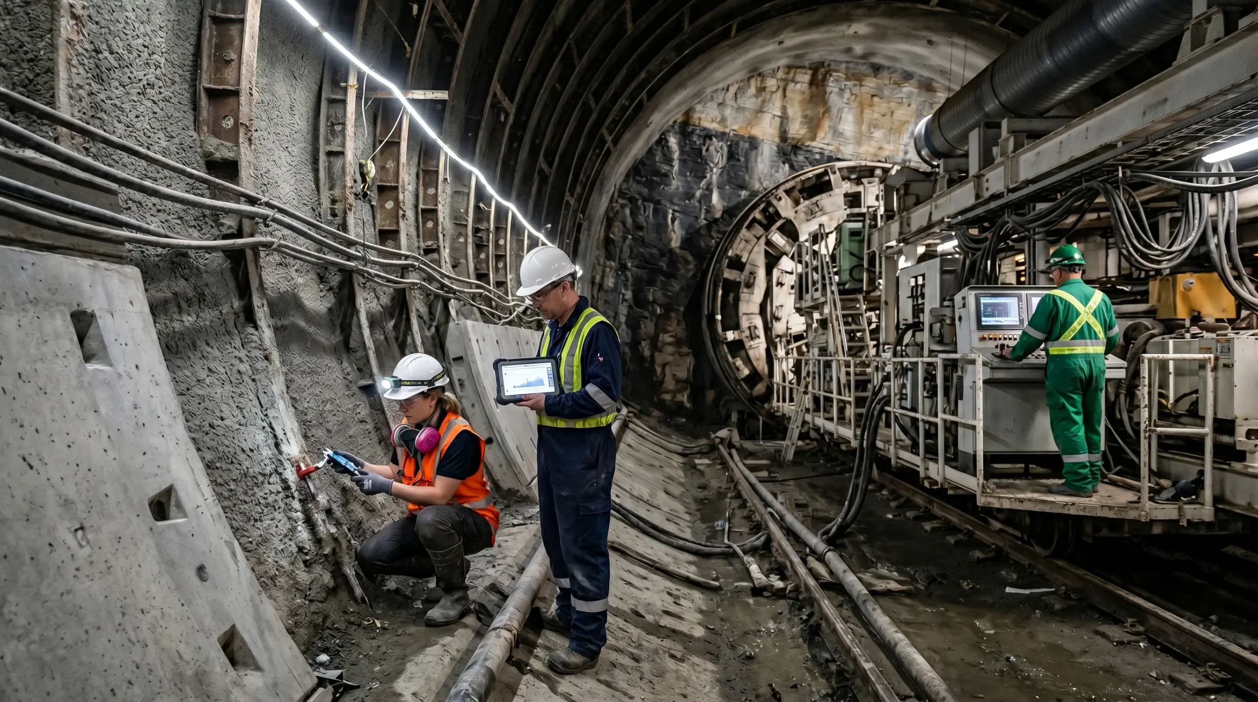
On 12 November 2023, at roughly 5:30 am local time, a 60-metre section of the Silkyara Bend–Barkot road tunnel collapsed along a Himalayan shear zone in Uttarakhand, India. Forty-one workers were trapped 230 metres inside the bore for seventeen days before the final rescue on 28 November (Uttarakhand Disaster Management Authority, 2024). The investigation identified an absent escape passage, no resident geologist on site for roughly twelve months before the failure, and an EPC bid that had compressed the geological investigation scope — a chain of decisions that turned a known shear zone into a hazard nobody had planned to recover from.
Ground collapse in tunnelling is rarely the surprise it appears to be. Across the published investigation record — Heathrow 1994, Silkyara 2023, Bangkok 2025, Seoul 2025 — the technical mechanism varies but the management pattern is consistent: warning signals exist; the response procedure does not. This article maps the dominant collapse mechanisms to their causes and primary controls, walks through the BS 6164:2019, OSHA 29 CFR 1926.800, and ITA/IMIA Code (3rd Edition, 2023) framework that governs tunnelling risk, and draws the practitioner lessons from each documented case.
Why Ground Collapse in Tunnelling Demands a Mechanism-First Approach
Tunnel collapse is not one event — it is a family of distinct failures with distinct triggers, distinct propagation paths, and distinct controls. Treating “collapse” as a single hazard is the reason generic site safety checklists keep failing in tunnelling.
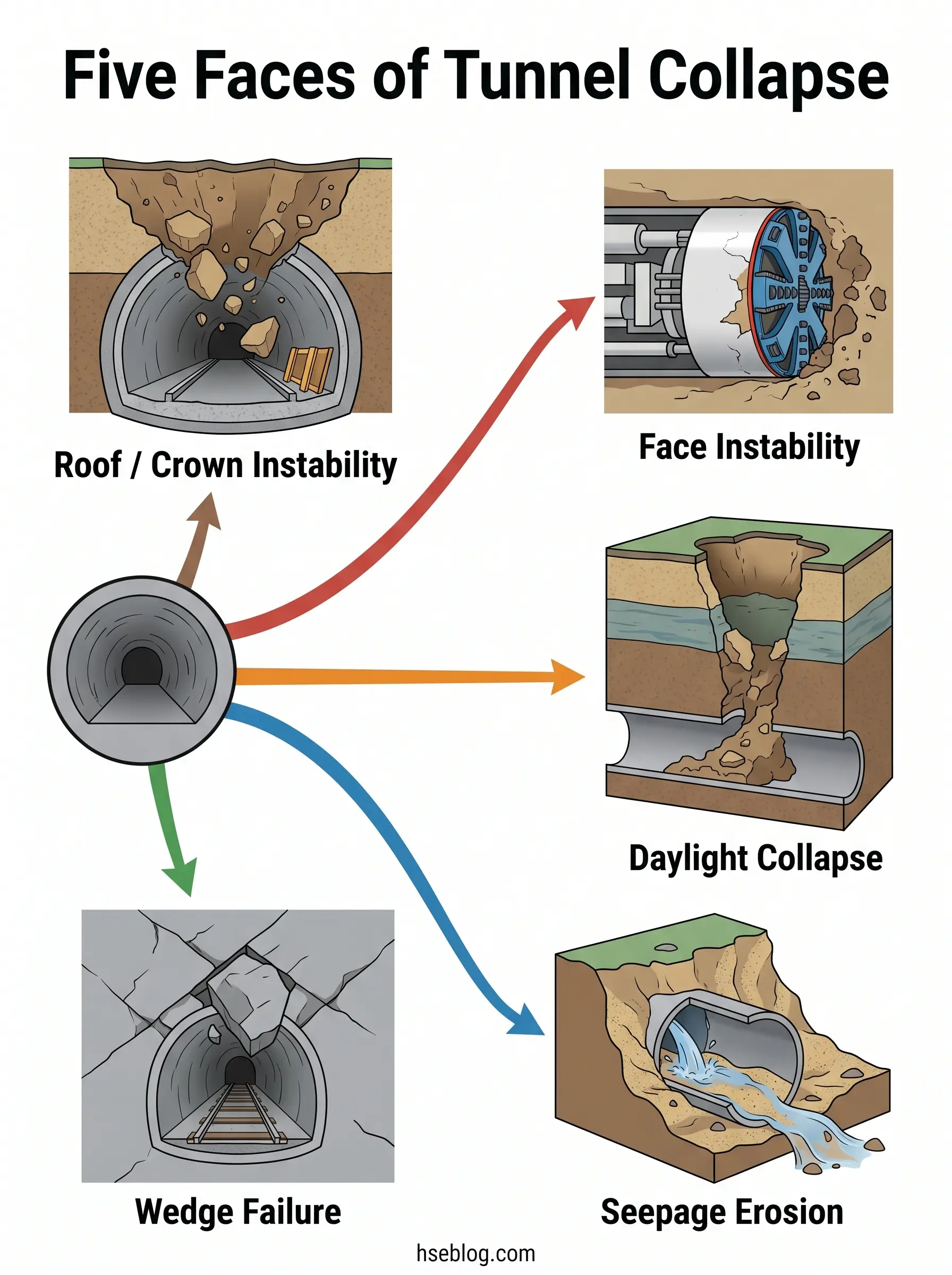
The recognised mechanism family runs across at least six modes:
- Roof or crown instability — progressive collapse of the excavation’s upper boundary, often the visible terminal stage of an earlier failure
- Face instability — loss of confinement at the working face, dominant in TBM drives and soft-ground NATM
- Daylight collapse — failure propagating from the tunnel up to the ground surface, producing a sinkhole or crater
- Sidewall shear and base heave — squeezing or yielding ground reacting against an undersized invert or support
- Wedge failure — a block bounded by intersecting discontinuities falling into the excavation, common in jointed rock
- Seepage erosion and piping — water-driven removal of fines that hollows the surrounding ground until structural support is lost
The same external trigger drives different mechanisms depending on ground type and excavation method. Groundwater in saturated sand produces seepage erosion and surface chimney collapse; in jointed rock it weakens discontinuities and triggers wedge failure; on a TBM drive with degraded tail seal integrity it overwhelms the face pressure balance.
The implication is direct. If you cannot name the mechanism, you cannot select the control.
Across the published investigation record, the chain pattern matters more than any single trigger. Heathrow 1994 was geological surprise compounded by NATM-in-clay inexperience, design margin compression, and a contract structure that transferred risk without competence. Silkyara 2023 was a known shear zone in a tender squeezed below the engineer’s estimate, missing escape passage, geologist absent for nearly a year before the failure. The cause is rarely one thing — and treating the visible mechanism as “the cause” is the analytical mistake that lets it repeat.
What Causes Ground Collapse During Tunnel Construction?
Across the published investigation record, the causes cluster into four interacting domains — and most documented collapses involve at least one factor from each. Single-cause explanations almost never survive the final report.
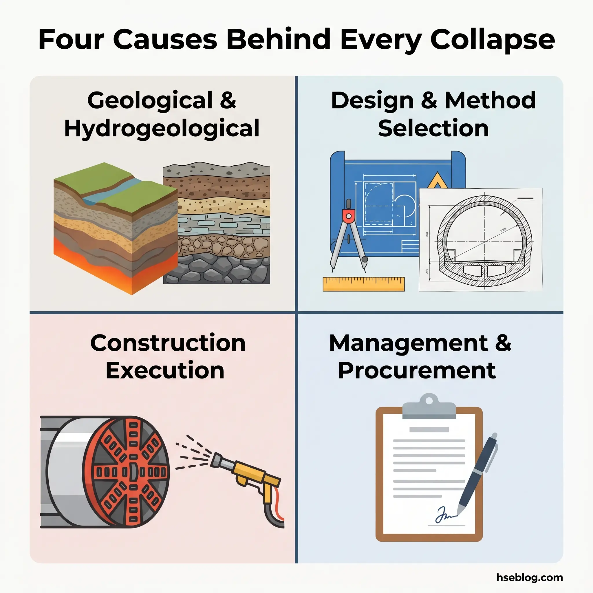
Geological and Hydrogeological Triggers
Fault zones, shear zones, karstic voids, mixed-face conditions, and water-bearing strata are the most-cited primary triggers in the tunnel-accident literature. Sousa and Einstein, in their peer-reviewed classification of tunnel-construction failures, treat geological surprise as the dominant external factor — but they also note that most surprises are foreseeable with adequate exploration ahead of the face.
The Guangdong composite sandy stratum case is illustrative: leakage progressed to full collapse in under three hours. That is faster than most monitoring review cycles. When the mechanism is seepage erosion in granular soil, daily data review is not a control — only continuous monitoring with pre-set trigger thresholds is.
Design and Method-Selection Errors
Choosing the wrong excavation method for the ground is the second persistent cause. NATM in soft soils with a high water table, gripper TBMs through fractured or unstable formations, and inadequate face pressure calculation on EPB or slurry drives all appear repeatedly in case reviews.
Conceptual frameworks for face stability — Horn’s silo theory (1961), the Jancsecz–Steiner wedge model (1994), Leca and Dormieux’s three-dimensional approach — exist precisely to set face support pressure. The failure is rarely the absence of these models; it is their misapplication when site ground conditions diverge from the design baseline.
Construction-Execution Failures
Round length pushed beyond the ground’s stand-up time, late ring closure on circular linings, poor shotcrete quality, insufficient grout fill of the segmental annulus, segment installation tolerances out of specification — each individually small, each documented as a contributor in cascading failure sequences.
The cascade matters more than the individual defect. A 10 mm tolerance miss on segment fit becomes a leakage path; the leakage erodes fines; the fines loss reduces support; the support loss produces convergence; the convergence is logged; the action is delayed; the failure propagates.
Management-System and Procurement Failures
The deepest cause in nearly every published investigation is not the technical trigger but the management decision made years earlier. Heathrow’s design-and-build contract structure transferred construction risk without transferring the technical competence to manage it. Silkyara’s EPC bid 24% below the engineer’s estimate compressed exactly the geological investigation scope that would have flagged the shear zone.
Risk-register hygiene is a related pattern. A risk register signed off at tender and never reopened is not a control — it is a compliance artefact. The ITA/IMIA Code (3rd Edition, 2023) is explicit that the register must be a live document continuously reviewed, and the documented losses across the industry trace, again and again, back to registers that stopped tracking once construction began.
Primary Failure Mechanisms of Tunnel Collapse
In tunnel design and excavation, the failure mode determines the control. Two collapses with identical surface symptoms can have completely different mechanisms beneath — and selecting the wrong control because the mechanism was misidentified is a recurring pattern in the investigation record.
The dominant mechanisms map to specific ground conditions, specific triggers, and specific primary controls:
| Mechanism | Typical ground | Typical trigger | Primary control |
|---|---|---|---|
| Roof / crown instability | Weak rock, soft ground, shallow cover | Insufficient initial support, late ring closure | Forepoling, lattice girders, early ring closure |
| Face instability | TBM drives in mixed-face or cohesive soil | Wrong face pressure, lost confinement | Calibrated EPB/slurry pressure, face logging |
| Daylight collapse | Shallow urban tunnels (cover < 2× diameter) | Propagation of internal failure upward | Settlement arrays, compensation grouting |
| Sidewall shear / base heave | Squeezing ground, weak floor strata | Excessive in-situ stress, inadequate invert | Yielding support, robust invert design |
| Wedge failure | Jointed / fractured rock | Block bounded by undetected discontinuities | Probing, rock-mass mapping, rock bolts |
| Seepage erosion / piping | Granular soils with hydraulic gradient | Water inrush at face or shield interface | Ground freezing, jet grouting, dewatering |
| Portal collapse | Shallow weathered rock, rainfall-exposed | Sustained rainfall, slope movement | Slope stabilisation, portal canopy, drainage |
Three of these mechanisms account for the highest fatality and third-party-impact share in the published record.
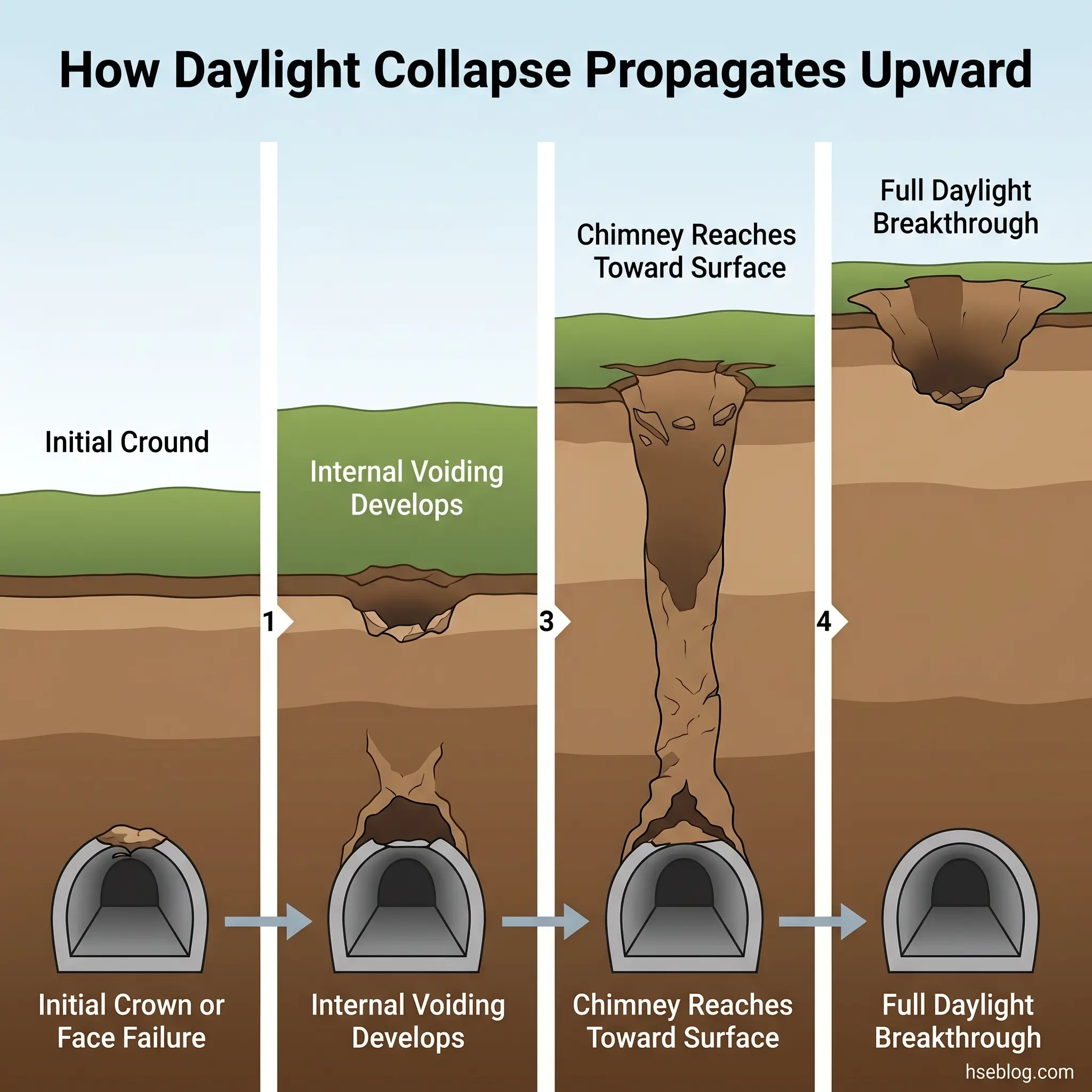
Daylight collapse is the largest-volume mode for NATM tunnelling and the most dangerous to the public. When a roof or face failure propagates upward through soft cover, the surface signature is a sinkhole or crater — and the failed volume can exceed the original excavation profile by an order of magnitude. The Bangkok Vajira Hospital sinkhole of September 2025 measured roughly 30 metres wide and 50 metres deep at a station-tunnel interface (Engineering News-Record, 2025), demonstrating the interface-vulnerability sub-mode in soft Holocene clay.
Wedge failure is the dominant mechanism in jointed and fractured rock and the hardest to predict from face inspection alone. The Seoul Myeongil-dong sinkhole (March 2025) was traced by the Republic of Korea’s Central Underground Accident Investigation Committee to a wedge-shaped block bounded by discontinuities not detected during pre-construction investigation, weakened by long-term groundwater decline and leakage from aging sewage pipes (Geoengineer.org reporting the Committee’s findings, 2025).
Seepage erosion is the fastest mechanism in granular soil with a hydraulic gradient. The process is mechanical, not chemical — fine particles are physically removed by flow, opening a piping channel that grows until structural collapse occurs. By the time visible water appears at the face in significant volume, the chain to collapse is often already established.
A common practitioner error is treating the visible failure as the mechanism, when the actual mechanism is several steps upstream. A roof collapse is often the terminal symptom of a face stability loss or a seepage erosion sequence that began hours earlier and was missed because monitoring was reviewed daily rather than continuously. The HSE NATM report, published 1996, makes the same observation: moderate or small deformation does not necessarily mean a sufficient safety margin remains where the failure mode is brittle.
How to Prevent Ground Collapse in Tunnelling
Prevention is layered, not singular — no single control prevents all collapse modes, and no checklist substitutes for matching the control to the identified mechanism. The practitioner’s job is to assemble the layers correctly for the ground, the method, and the project’s risk profile.
Competent-person note: This article provides general HSE knowledge. Life-critical tunnelling decisions — face support pressure selection, ground improvement design, monitoring trigger setting, evacuation initiation — must be planned and supervised by a competent person with relevant training, jurisdiction-specific authorisation, and site-specific risk assessment. Recognised training pathways include NEBOSH construction qualifications, IOSH-accredited courses, and equivalent regional certifications. The information here does not replace site-specific competent supervision.
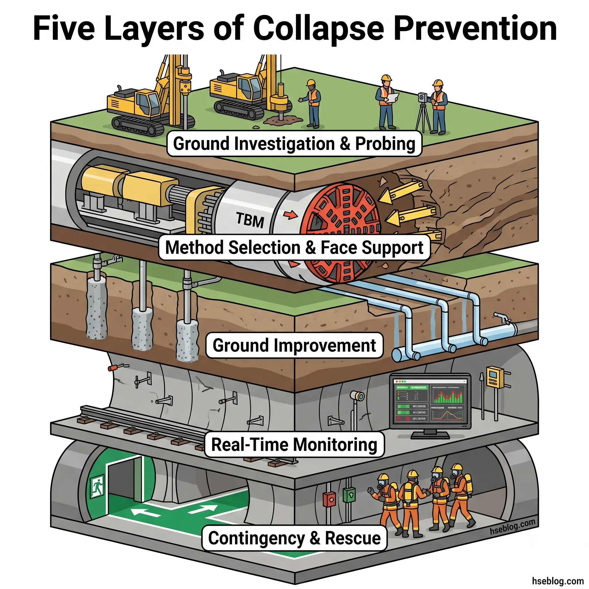
Pre-Construction Ground Investigation and Probing
Tiered ground investigation runs from desk study and geophysical survey, to ground investigation boreholes, to probing ahead of the face during construction. The ITA/IMIA Code (3rd Edition, 2023) sets stage-by-stage risk identification across project development, design, tender, and construction as the baseline.
Probing ahead of the face is the layer most often cut under cost pressure and most often cited in subsequent investigation reports. Horizontal seismic profiling, tunnel seismic prediction, and forward percussion drilling are the standard techniques; the choice depends on the geology and on what the project most needs to detect — water-bearing zones, fault planes, or voids.
Excavation Method Selection and Face Support
Matching the TBM type to ground conditions is non-negotiable. EPB shields work in cohesive and mixed ground where the spoil forms a sealing plug; slurry shields are required in water-rich granular soils where bentonite suspension provides face support; gripper TBMs depend on the surrounding rock for thrust and are unsuited to unstable formations.
Face support pressure is calculated as the sum of lateral earth pressure, hydrostatic pressure, and a safety margin set to ground variability. The 2018 Foshan Metro Line II shield-tail seal failure illustrated what happens when pressure management lags ground change in water-rich sand — and tail seal integrity is the often-overlooked second half of the face pressure system.
Ground Improvement Techniques
When the in-situ ground cannot support excavation safely, the engineering response is to improve the ground itself before the face arrives. The principal techniques each suit different conditions:
- Permeation grouting — fills voids in granular soils with sodium silicate or microfine cement; suits sands and fine gravels
- Jet grouting — creates columns or blocks of soilcrete; suits a wide range of soils but limited in very stiff clays
- Compensation grouting — active settlement control during a TBM drive, injecting grout from above to offset settlement as it develops
- Ground freezing — uses brine circulation or liquid nitrogen to form a temporary frozen mass; preferred where chemical grouting is infeasible, often used for shaft sinking and cross-passage construction
- Soil mixing — mechanically blends cementitious binder with in-situ soil to create reinforced soilcrete elements
Technique selection follows mechanism. Seepage-erosion risk → grouting or freezing to cut the hydraulic gradient. Face instability → jet grouting to pre-support the face zone. Surface settlement risk on shallow tunnels under sensitive buildings → compensation grouting.
Monitoring and the Observational Method
Real-time instrumentation combines convergence pins, surface settlement arrays, piezometers, strain gauges, and TBM operational data (face pressure, thrust, torque, advance rate, spoil mass balance). Recent additions include AI-augmented warning systems that flag anomalies in real time rather than at scheduled review.
The critical step beyond installation is the trigger-response chain:
- Define amber and red trigger levels at design stage, derived from the predicted behaviour envelope
- Specify the response action for each trigger — not just notification, but who decides what
- Name the decision-maker for each trigger and their alternate, with 24-hour coverage
- Pre-authorise the response so it can be enacted without further escalation when the trigger fires
- Drill the response — at minimum, a tabletop exercise per trigger level per shift rotation
Where this chain is incomplete, monitoring becomes a post-hoc explanation rather than a control. The HSE concluded essentially this point in the Heathrow report: monitoring detected the movement; the management system did not act on it in time.
A documented limitation of the observational method needs explicit recognition. For brittle or spontaneous loss-of-stability failures, small or moderate deformation does not indicate that a safe margin remains. Monitoring is not a substitute for probing ahead of the face when the mechanism in play can fail without progressive warning.
Contingency Planning and Emergency Response
Contingency is the last line, not a paperwork exercise. OSHA 29 CFR 1926.800 requires a rescue team during all phases of underground construction in the US jurisdiction. BS 6164:2019 provides the equivalent UK code-of-practice requirements. The ITA/IMIA Code treats contingency planning as part of the live risk register, not a separate document.
The Silkyara collapse made the contingency point starkly. The tunnel had no separate escape passage. A recoverable incident became a 17-day rescue through 230 metres of debris because the basic contingency provision — a parallel escape — was absent.
The Risk Management Framework: BS 6164, ITA/IMIA Code, and OSHA Subpart S
Three principal frameworks govern tunnelling risk in international practice. They are complementary rather than redundant, and on cross-border projects all three commonly apply through contract specification.
Legal disclaimer: Regulatory content here reflects general HSE professional understanding of the cited frameworks as of 2025. It is not legal advice. Specific compliance questions, enforcement situations, or prosecution risk should be directed to qualified legal counsel in the applicable jurisdiction. The regulatory content in this article was last reviewed for currency on the date shown in the byline block.
| Standard / Code | Jurisdiction | Core requirement | Enforceability |
|---|---|---|---|
| BS 6164:2019 — Health and safety in tunnelling | UK | Recommendations for shaft sinking and tunnelling H&S; technical detail on monitoring, ventilation, atmospheric testing | Code of practice; referenced by HSE inspectors and the BTS/ABI Joint Code |
| OSHA 29 CFR 1926.800 — Underground Construction | US | Competent person at all times; check-in/check-out; rescue team during all phases; air monitoring; mechanical ventilation | Federal regulation; civil penalties, six-figure exposure for willful violations |
| ITA/IMIA Code of Practice, 3rd Edition (2023) | International | Stage-by-stage risk identification; live risk register; reduction to ALARP; auditable risk-management trail | Contractually binding when referenced by the project insurance policy or contract |
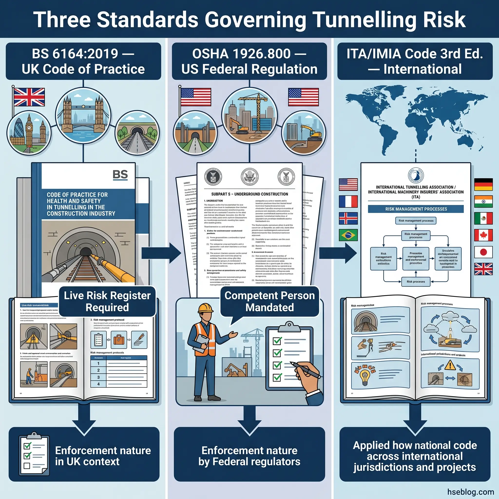
OSHA’s text on the competent person is narrower than BS 6164’s treatment of role-based accountability; the stricter and more technically detailed reading is BS 6164:2019 where its scope applies. The ITA/IMIA Code adds the strongest requirement on risk-register currency — explicitly that the register is a live document continuously reviewed, not a tender-stage artefact.
None of these frameworks override national statutory law. In the UK, the Health and Safety at Work etc. Act 1974 sections 2(1) and 3(1) provide the statutory basis on which HSE prosecuted Balfour Beatty (£1.2m) and Geoconsult (£0.5m) after the Heathrow 1994 collapses (UK HSE, 2000). In the US, the OSH Act 1970 underpins 29 CFR 1926.800. Equivalent national frameworks operate in every jurisdiction with significant underground construction activity.
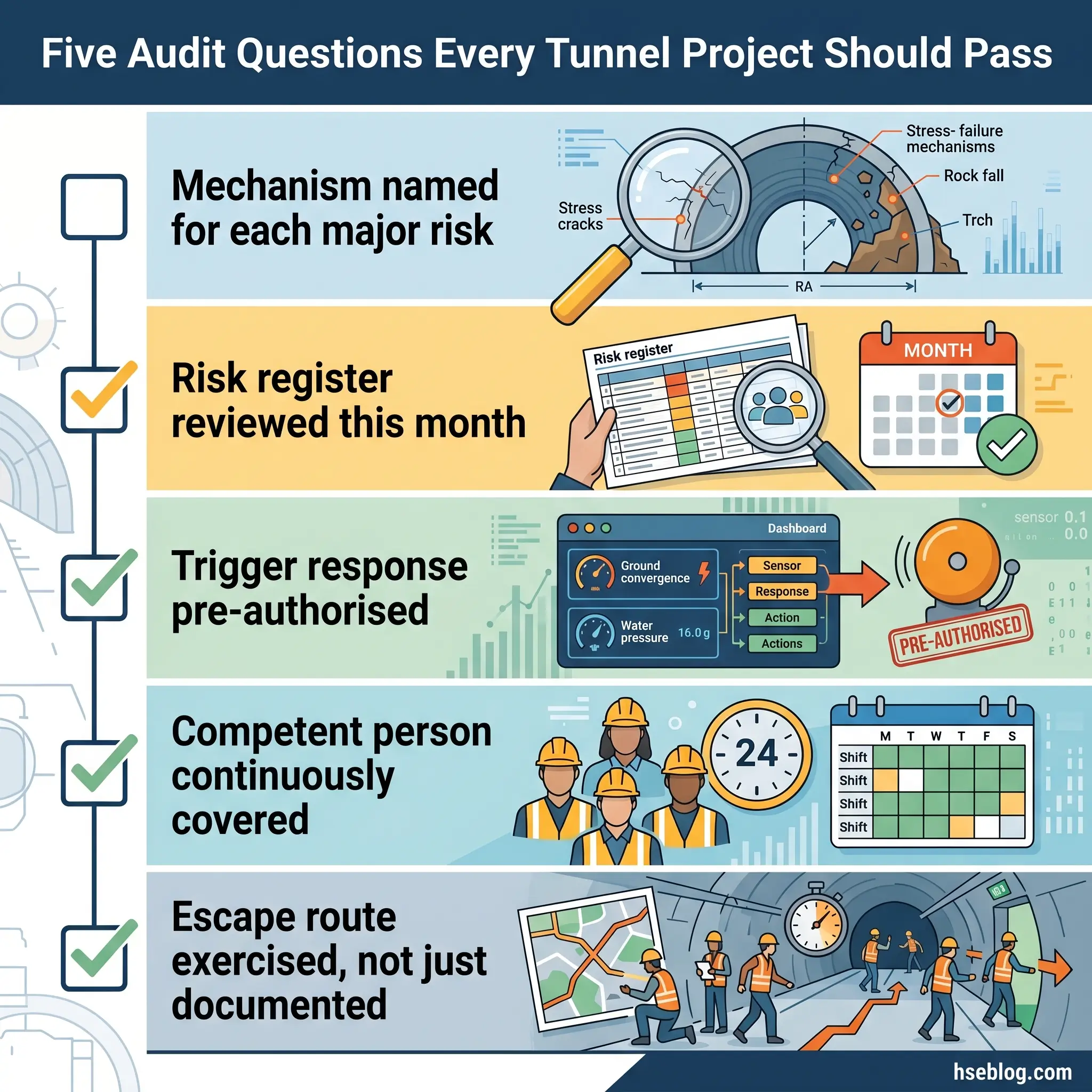
The field-level reading of all three frameworks converges on the same operational tests. Is there a competent person present, named, and authorised? Is the risk register dated within the last review cycle and showing recent entries? Are monitoring trigger responses pre-authorised and drilled? Is the rescue capability present and exercised? Auditors typically test these four questions before any deeper review, and a project that fails them rarely passes the deeper review either.
Lessons from Documented Tunnel Collapse Investigations
HSE’s 2006 bored-tunnelling third-party risk study catalogued 66 NATM incident cases and 42 non-NATM emergency events across worldwide tunnel construction and operation (HSE, 2006). Four cases — spanning thirty years and four jurisdictions — illustrate the recurring patterns most relevant to current practice.
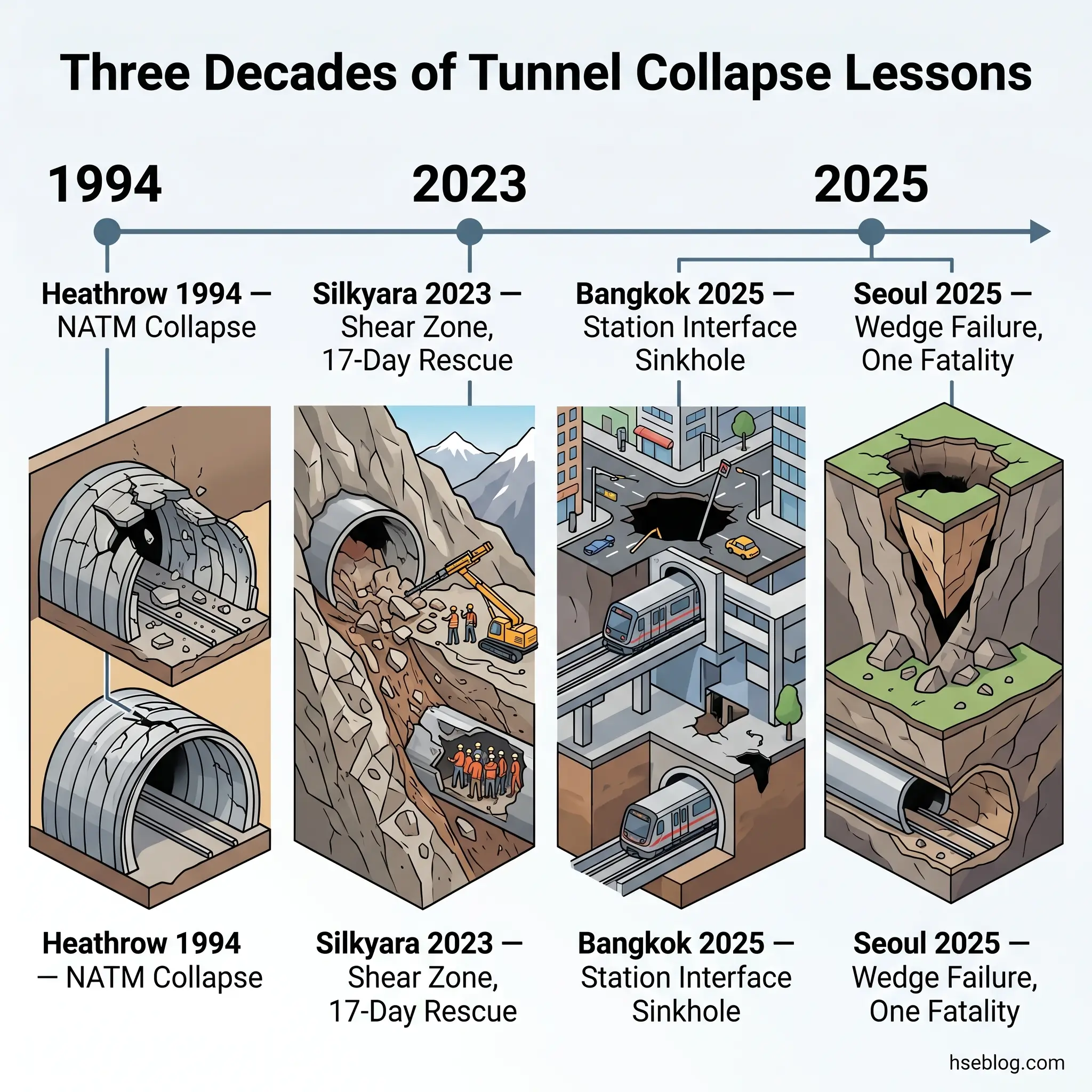
Heathrow Central Terminal Area, London — October 1994
In the early hours of 21 October 1994, three NATM tunnel headings under the Heathrow Central Terminal Area collapsed in sequence. The HSE investigation, published as the 1996 NATM Report and supporting documents through 2000, identified design margin compression, NATM-in-London-clay inexperience, missed monitoring signals, and a design-and-build contract structure that transferred construction risk without commensurate technical competence (UK HSE, 2000). The outcome: £1.2 million fine on Balfour Beatty Civil Engineering, £0.5 million on Geoconsult ZT GmbH, under HSWA 1974 sections 2(1) and 3(1).
Lesson: Contractual structure is a tunnelling safety variable. Where contracts transfer risk without commensurate competence, the management system fails before the geology does.
Silkyara Bend–Barkot Tunnel, Uttarakhand, India — November 2023
A 60-metre section collapsed along a Himalayan shear zone on 12 November 2023, trapping 41 workers for 17 days until rescue on 28 November (Uttarakhand Disaster Management Authority, 2024). The investigation identified an absent separate escape passage, a geologist not on site for approximately 12 months before the failure, and an EPC bid that had compressed the geological investigation scope below what the route’s geology warranted.
Lesson: Bid compression that targets ground investigation is bid compression that targets the project’s ability to identify the failure mechanisms it is about to encounter. A separate escape passage is not a cost line item; it is what determines whether a survivable incident remains survivable.
Bangkok Vajira Hospital Sinkhole — September 2025
On 24 September 2025, a daylight collapse roughly 30 metres wide and 50 metres deep opened above the MRT Purple Line metro extension at the Vajira Hospital station interface (Engineering News-Record, 2025). Investigation identified soil and water infiltration at the station-tunnel interface, compounded by rupture of a 1.2-metre water main. The $2.2 billion project was halted.
Lesson: Station-tunnel interfaces are vulnerability points in their own right, distinct from open-line tunnelling sections. Adjacent utility integrity is part of the tunnel’s geotechnical environment, not external context.
Seoul Myeongil-dong Sinkhole — March 2025
A sinkhole opened in March 2025 above the Subway Line 9 extension, with one fatality. The Republic of Korea’s Central Underground Accident Investigation Committee confirmed a wedge-shaped block bounded by undetected discontinuities, weakened by long-term groundwater decline from prior tunnel works and leakage from aging sewage pipes (Geoengineer.org reporting the Committee’s findings, 2025). Committee recommendations included reduced ground-investigation spacing and adoption of non-drainage TBM methods in deep weathered zones.
Lesson: Discontinuities are the silent variable. Pre-construction investigation spacing tuned to detect them — not just to characterise generic ground type — is the only protection against wedge mechanisms that give no progressive warning.
Frequently Asked Questions
Conclusion
The industry’s recurring mistake in tunnel collapse prevention is treating the visible mechanism as the cause. Heathrow’s roof failure, Silkyara’s shear zone, Bangkok’s interface breach, Seoul’s wedge — each had warning signals preceding the failure, and each had a management system that did not have a defined, named, pre-authorised response to those signals. The geology is rarely the surprise. The unprepared response is.
The highest-impact change available to most tunnelling projects is the trigger-response chain itself: every monitored parameter has named amber and red thresholds; every threshold has a pre-defined response action; every response has a named decision-maker with 24-hour coverage; every response is drilled before the face advances. This change costs little, draws on the standards already in place, and directly prevents the pattern where monitoring catches the movement but the management system processes it as information rather than a control input.
Ground collapse in tunnelling will not be eliminated by another revision of the standards. BS 6164:2019, OSHA 29 CFR 1926.800, and the ITA/IMIA Code (3rd Edition, 2023) already specify, between them, what good practice looks like. The gap is execution, and execution is a project culture question more than a technical one. The projects that don’t collapse are the ones where the response procedure exists before the geology tests it.