
On 17 July 2007, a driver at a solvent distribution terminal opened a fill line to transfer VM&P naphtha into a 15,000-gallon above-ground storage tank. It was routine — the terminal had run the same transfer thousands of times before. Inside the tank, a float on the level-gauge linkage had worked loose over years of service. As charged liquid entered the vapor space, static accumulated on the now-isolated metal float, built to breakdown voltage, and arced. The resulting explosion destroyed the tank farm, sent a fire visible for miles, and forced the evacuation of roughly 6,000 residents from surrounding neighborhoods. Three months later a near-identical static event at the company’s Iowa terminal injured workers during an ethyl acetate tote transfer.
Neither incident was caused by missing equipment. Both were caused by trusting that grounding and bonding, once installed, stay effective — and by assuming the two controls are enough for every flammable liquid. In the solvent blending facility I’ll be referencing throughout this article, we run more than eighty drum transfers a shift and every one of them depends on two copper cables and a clamp making clean metallic contact. When that contact degrades, the math flips in seconds: a 1-millijoule solvent vapor meets a 20-millijoule spark. This article covers what static discharge actually is, how grounding and bonding each prevent it, how to apply both correctly, how to verify the system works, and where — as Barton Solvents proved — the basics fall short.
What Static Discharge Is and Why It Ignites Fires
Static accumulates when two dissimilar materials touch and separate. This is triboelectric charging — the same mechanism that lifts hair off a comb, except the “comb” is the inside wall of a transfer hose or pump rotor, and the “hair” is the flammable liquid itself. Charge separates at the interface, travels with the liquid into the receiving vessel, and sits there until it finds a path back to earth.
If the receiving vessel is conductive and grounded, charge drains harmlessly. If it is isolated — a plastic drum, a metal drum sitting on a plastic containment pallet, a float disconnected from its tank wall by a worn linkage — voltage climbs. Ungrounded isolated conductors in ordinary industrial operations have been measured above 30 kV. At somewhere between 15 and 30 kilovolts across a typical air gap, the dielectric strength of air breaks down and the charge jumps.
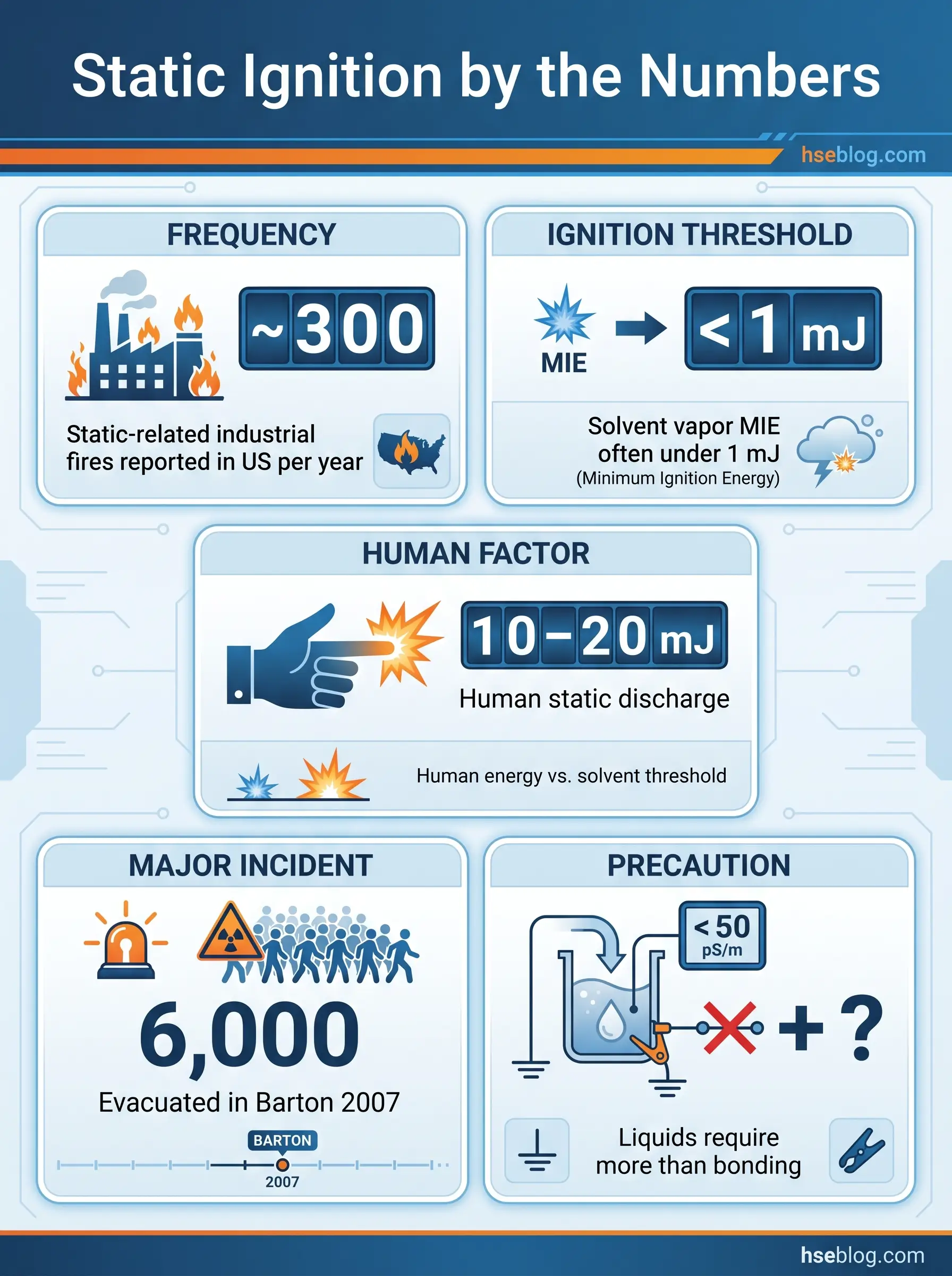
NFPA 77 classifies the resulting discharges by geometry and energy. A spark discharge between two charged conductors is the most energetic and the most lethal — it is what happened at Barton. A brush discharge between a conductor and an insulator carries less energy but still ignites most solvent vapors. A propagating brush discharge, seen on charged plastic films and FIBC surfaces, releases enough energy to ignite dusts. The number that determines whether any of them matters is the Minimum Ignition Energy of the atmosphere present at the moment of discharge:
| Flammable atmosphere | Typical MIE |
|---|---|
| Hydrogen in air | ~0.02 mJ |
| Hexane vapor | ~0.24 mJ |
| Acetone vapor | ~1.15 mJ |
| Fine metal dust (aluminum) | ~0.1–1 mJ |
| Coarse plastic dust | ~10–30 mJ |
Put the two numbers together and the picture is unforgiving. A person who walks ten steps across a dry warehouse floor in winter carries an ignition source several hundred times more energetic than the MIE of the vapor in a partly filled solvent drum. That is before the flow itself adds charge to the liquid.
Three conditions have to align for a static fire: charge generation, charge accumulation on an isolated body, and a flammable atmosphere present at the moment of discharge. Bonding addresses the geometry that allows accumulation between objects. Grounding addresses accumulation on the overall system. Removing the atmosphere — dealt with later in this article — addresses the third and is sometimes the only realistic control.
Grounding vs. Bonding: The Critical Distinction
Most static-fire investigations start with the same finding: the operator thought the equipment was grounded, and by strict definition it was, but it wasn’t bonded. Or the two drums were bonded to each other but the pair was floating. The words matter because each control fixes a different half of the problem.
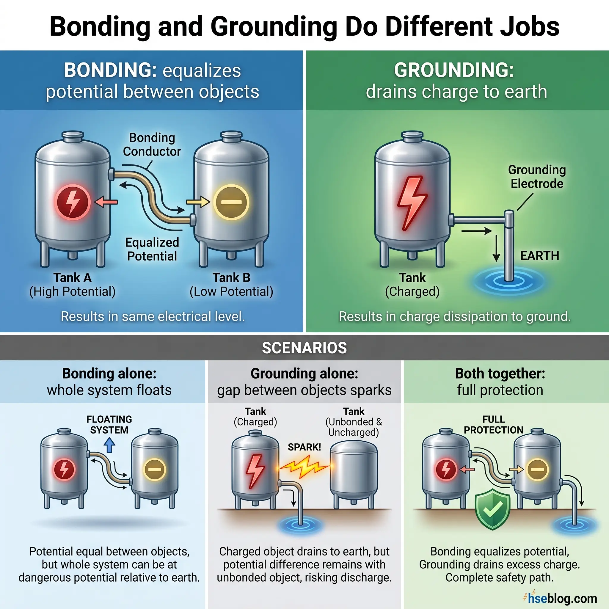
Bonding is the act of connecting two or more conductive objects with a low-resistance wire so they share the same electrical potential. It prevents sparks between the bonded objects. It does nothing about charge the bonded system acquires from an outside source — turbulent liquid flow, sliding powder, airborne particles.
Grounding (or earthing) is the act of connecting a conductive object to earth so accumulated charge has a continuous path to drain. It prevents voltage from rising on the grounded object. It does nothing about the potential difference between two separate objects that aren’t connected to each other.
The canonical drum-to-pail transfer makes the distinction concrete. Ground the drum only, and the drum sits at earth potential while the pail charges up as liquid flows in — a spark jumps between pail and nozzle at the last inch of pour. Bond the drum to the pail only, and both float at the same rising voltage — a spark jumps from the bonded pair to the nearest grounded thing, which is usually a worker’s hand or the dispensing rack frame. You need both. Bond the pail to the drum, ground the drum to earth, and the entire assembly drains faster than the liquid can charge it.
Where the Risk Concentrates
The hazard concentrates wherever three conditions overlap — a flammable or combustible atmosphere forms routinely, the process generates charge, and containment is not continuously earthed. NFPA 77 scopes its recommended practice to chemical, petroleum, printing, and calendaring operations, and field experience extends that list considerably.
- Flammable liquid transfer, including drum-to-pail dispensing, IBC and tote filling, and tank truck or rail car loading. This is the single largest category of reported static fires and the one most readers of this article will touch daily.
- Aviation fuel servicing, governed by NFPA 407, where nozzle-to-aircraft bonding is mandatory before any fuel flows.
- Pneumatic conveying of powders and any combustible dust handling where charge builds on dust particles as they slide through ducts and impact on vessel walls.
- Solvent-based coating, printing, calendaring, and film-converting, where high-speed moving webs and rollers accumulate charge on both the product and the machine.
- Pharmaceutical solvent handling and blending, especially the decanting and addition of organic solvents into reactors or dryers with flammable vapor space.
- Laboratory dispensing and waste solvent consolidation, where small-volume operations and plastic squeeze bottles let crews believe the hazard is negligible.
- FIBC filling and emptying, where flexible polymer fabric can accumulate thousands of volts unless the correct bag type (B, C, or D per IEC 61340-4-4) is matched to the atmosphere.
If your facility runs any two of these activities in adjacent areas, your static risk is not abstract — it is a daily operational condition.
Case Study: The Barton Solvents Static Explosion
I return to Barton Solvents in every toolbox talk I deliver on this topic because the incident compresses every failure mode the industry would rather abstract away.
On the day of the Wichita incident, VM&P naphtha was being transferred from a bulk tank into a 15,000-gallon vertical storage tank. The liquid had a measured electrical conductivity of 3 pS/m — well below the 50 pS/m threshold at which charge is considered to relax on the same timescale as normal handling. Its MIE was about 0.22 mJ. The tank had a standard level-gauge float assembly, bonded to the tank shell when installed. Over service life, the linkage between float and bonding point had loosened. At the moment of transfer, the float was electrically isolated from the tank wall. Charged liquid entered the vapor space, the float charged in parallel, voltage rose across a millimeter-scale air gap between float and linkage, and the dielectric of air broke down. A single spark ignited the vapor space. The facility was destroyed. The follow-on incident at the Des Moines terminal three months later involved an ethyl acetate tote being filled through a nozzle, hose, and counterweight that were not bonded to the tote or grounded — a mirror-image failure in different equipment.
The lesson the CSB wrote into the industry: bonding and grounding as normally understood are necessary but not sufficient for static-accumulating liquids. Low-conductivity fuels hold charge long after flow stops. If the procedure does not also address flow velocity, relaxation time, or inerting, the fire is a question of when, not whether.
The Barton investigation also flagged that the SDS for VM&P naphtha at the time understated the static hazard relative to its conductivity and MIE, and that the company’s own procedures treated static as a generic hazard rather than a product-specific one. Both findings changed how many bulk terminals now write transfer procedures.
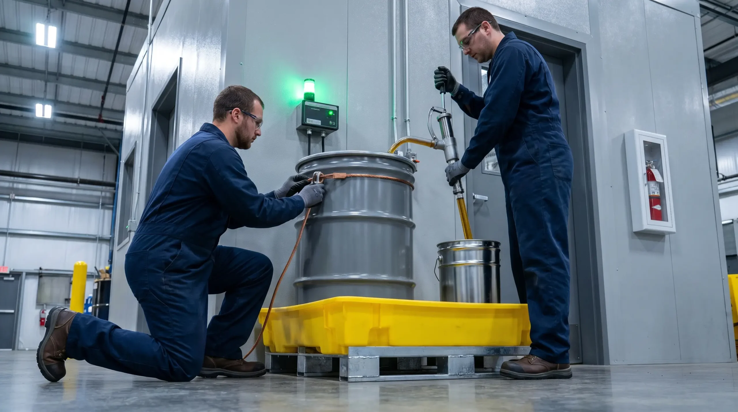
The Correct Procedure for Bonding and Grounding Containers
This is the operational heart of the article. The sequence below covers the most common scenario — dispensing a flammable liquid from a metal drum into a smaller metal container — and then extends to plastic drums and tank-truck loading.
Dispensing from a Metal Drum into a Metal Pail
The order of connection matters. Power the system down and close all valves before touching any hardware.
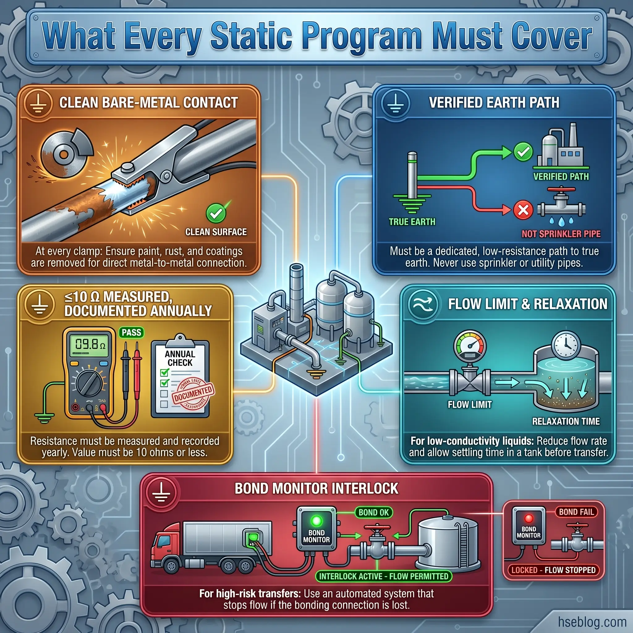
- Verify the earth point. The grounding cable terminates at a dedicated grounding electrode, a grounded building steel member, or a dedicated ground bar bonded back to the building electrical grounding system. Never a sprinkler pipe, gas pipe, or process pipe.
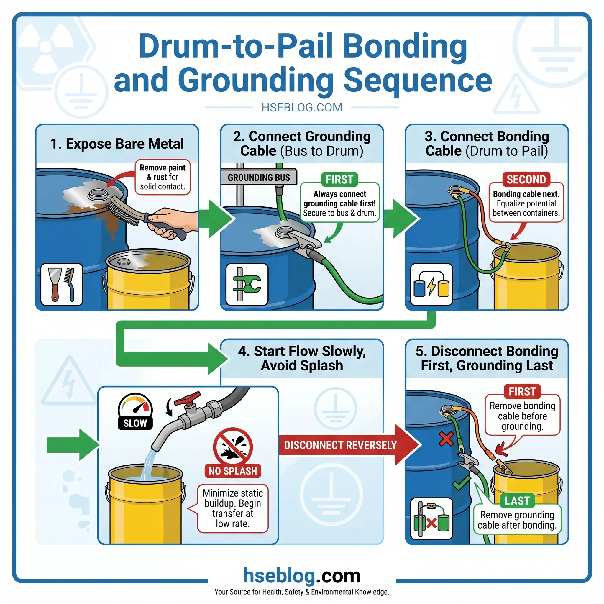
- Clean the contact points. Paint, rust, powder coating, dirt, and wax all defeat the ground path. Expose bare metal at each clamp contact — the drum rim, the pail rim, and the ground bus. A wire brush and thirty seconds of abrasion is the difference between a working system and a placebo.
- Attach the grounding cable first — ground bus to drum, metal-to-metal, with sharp-tooth clamps that bite into the bare contact patch.
- Attach the bonding cable — drum to pail, metal-to-metal, same clamp quality.
- Discharge yourself. Touch the grounded drum body before opening any valve. This drains personal static before you handle any charged surface.
- Start the flow slowly. Open the pump or valve to minimum rate first, let the liquid reach the bottom of the receiving pail, then ramp up. Splash filling is a charge multiplier.
- Reverse on disconnection. When the transfer is complete, remove the bonding cable first, grounding cable last. This keeps the system earthed until the moment it is physically separated.
Dispensing Into Plastic or Poly Drums
Plastic is where most crews stop thinking, and where OSHA’s 1999 interpretation letter explicitly warns that the ordinary procedure does not suffice. Plastic does not conduct, so static builds on both the liquid column and the outer surface. For modern poly drums with embedded grounding wires, bond the embedded wire to earth the same way you would a metal drum. For a plain polyethylene drum, the practical controls are a grounded metal dip tube reaching the bottom of the vessel, a grounded flame-arrester funnel, and a grounded metal plate under the drum tied back to the facility ground bar. Reduce flow rate to a maximum of 1 m/s until the dip tube is submerged.
Tank Trucks and Rail Cars
For loading-rack operations governed by API RP 2003, the sequence is longer but the principle is identical. Ground the truck chassis before opening any dome or hatch. Use bonding cables across any nonconductive hose sections. Restrict flow velocity to 1 m/s (3 ft/s) until the fill pipe is submerged to a minimum of two pipe diameters. Interlock the loading pump with a ground-proving system so product cannot flow unless ≤10 Ω continuity to earth is verified and maintained.
Watch For: A clamp biting into a painted drum handle looks like a bond. It isn’t. Check the clamp teeth for paint flakes between every third drum — if they’re coated, clean them or swap the clamp.
Equipment That Actually Works
The procedure is only as good as the hardware. Improvised bonding with jumper cables or general-purpose alligator clips is the most common hardware failure I see on facility walk-throughs. A proper bonding and grounding cable is stranded copper or braided stainless steel, insulated against chafing, terminated in heavy-duty clamps with sharp, offset teeth engineered to penetrate surface contamination. Cable length is typically 3 to 10 feet, long enough to reach without tension. Clamps with smooth jaws — the kind sold in automotive stores — will not bite through paint.
Grounding reels, mounted above work points, retract cable out of the way and make consistent use far more likely than loose cables left on the floor. Where the transfer involves static-accumulating liquids or high-value risk, active static bond monitors with visual indication and a process interlock are now standard practice at bulk terminals. A green LED confirms a ≤10 Ω path; a red indicator inhibits the loading pump until the fault is cleared. NFPA 77 (2024) explicitly recognizes self-monitoring systems as an acceptable substitute for periodic manual testing, which is the most meaningful shift the standard has made in two revisions.
For personnel working in hazardous areas, dissipative flooring, heel grounders, and conductive or static-dissipative footwear (compliant with ASTM F2413 and ESD standards) reduce human charge to safe levels. OSHA 29 CFR 1910.136(a) requires protective footwear where a static-discharge hazard remains after other controls.
Testing and Verifying the Ground Path
A ground connection you haven’t measured is an assumption. Verification is where most facilities — and most competitor articles — fall silent. The confusion is not helped by the fact that different standards quote different resistance thresholds, because they are talking about different object classes.
| Standard | Object / Application | Maximum Acceptable Resistance |
|---|---|---|
| NFPA 77 (2024), §7.4 | Bonded/grounded metallic (conductive) systems | 10 Ω |
| NFPA 77 (2024), §7.4 | Static dissipation from a dissipative object | 1 × 10⁶ Ω |
| API RP 2003 (2015, reaffirmed 2020) | Tank truck / rail loading-rack ground path | 10 Ω |
| IEC TS 60079-32-1 (2013 + AMD1:2017) | Conductive grounded object | 10 Ω |
| IEC TS 60079-32-1 | Dissipative surface / FIBC Type C | 10⁴ – 10⁹ Ω |
The rule of thumb: for any bolted, clamped, or welded metallic transfer system, test for 10 Ω or less using a low-resistance ohmmeter (DLRO). For intentionally dissipative materials (ESD flooring, antistatic hoses, Type C FIBCs), a megohmmeter verifies the object is within its dissipative band — neither a perfect conductor nor a perfect insulator. Conductive objects inside the dissipative range are not grounded and will accumulate charge.
NFPA 77 recommends annual documented resistance testing with records kept for audit. Where a self-testing bond monitor is installed, the continuous verification substitutes for the annual check. On top of formal testing, visual inspection of clamps, cables, and contact points should happen before every transfer. I’ve caught more bad grounds with a flashlight and a wire brush than with an ohmmeter.
Common Mistakes That Make Grounding Useless
These are the failure modes that show up in incident reports, insurance loss investigations, and audit findings often enough that they deserve their own checklist. If any one of them exists on your site, the ground path is probably compromised regardless of what the single-line drawing says.
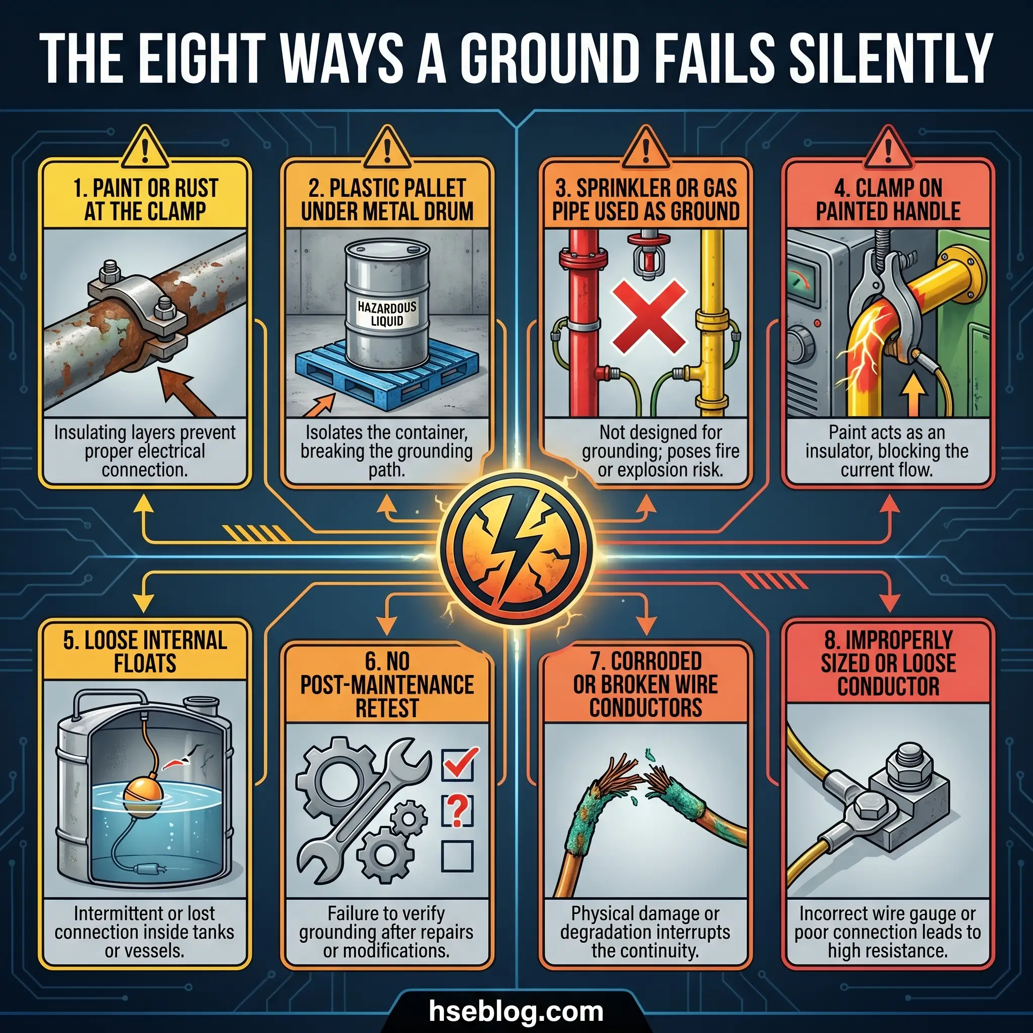
- Clamping through paint, rust, grease, or powder coating. No metal-to-metal contact means no ground path, even if the cable is bright new copper.
- Metal drum on a plastic containment pallet with no ground strap. The pallet is an insulator. The clamp on the drum does nothing if the drum is isolated from earth.
- Using sprinkler piping, gas piping, or process piping as a ground electrode. Prohibited by NFPA 13, NFPA 24, and NFPA 70 for good reason — galvanic interaction, current interference, and code violation.
- Assuming rails ground a rail car. Nonconductive wear pads, grease, and rust at the axle can isolate the car. Use a dedicated bond to a verified ground.
- Clamping to a painted drum handle or vented bung ring. The clamp looks attached but the body of the drum isn’t in the circuit.
- Ignoring internal tank components — floats, level-gauge linkages, dip tubes — that were bonded at installation but may have drifted over service life. This is the Barton failure mode.
- Skipping re-verification after maintenance, repainting, or re-coating. Paint is the most common post-turnaround cause of open ground.
- Trusting a bond monitor without checking the contact surfaces. A green LED confirms continuity at the clamp — it does not confirm the clamp is on bare metal.
Beyond Bonding and Grounding: Controls for High-Risk Cases
The Barton lesson is that bonding and grounding alone don’t cover every scenario. For low-conductivity liquids, fine combustible dusts, and FIBCs handling flammable powders, the ignition mechanism persists even when the hardware is perfect. Additional controls are needed.
Flow velocity limitation — cap inlet velocity at 1 m/s until the fill pipe is submerged to at least two pipe diameters. This is the single most effective tank-filling control for non-conductive liquids, referenced in both API RP 2003 and IEC 60079-32-1.
Relaxation time — wait 30 to 60 seconds after flow stops before sampling or gauging a low-conductivity liquid, longer for very low conductivities. Charge carried by the liquid bleeds off once the motion stops, but only if the tank is conductive and grounded.
Anti-static additives raise the liquid’s conductivity above ~50 pS/m so normal relaxation times apply. Common in aviation fuel and some solvent blends.
Inerting with nitrogen per NFPA 69 removes the atmosphere, not the ignition source. Where the vapor space cannot be reliably kept below its limiting oxygen concentration, inerting is the only control that defeats all three legs of the fire triangle at once.
Dip-pipe filling instead of splash filling. Submerged-fill lines reduce both turbulence and aerosol generation, cutting charge generation substantially.
FIBC bag selection per IEC 61340-4-4: Type A bags are only for non-flammable environments; Type B for combustible dusts only; Type C (grounded) for flammable vapors or dusts when the ground tab is verified before filling; Type D (dissipative) where grounding cannot be guaranteed. Mixing bag types between operations is a recurring audit finding.
Humidification to 40–60 percent relative humidity where the process tolerates it. Surface conductivity of many insulators rises sharply with moisture, draining charge before it accumulates.
Regulatory and Standards Framework
The legal and consensus stack is dense, but most sites only need to internalize half a dozen documents. OSHA 29 CFR 1910.106(e)(6)(ii) is the first. It states that Category 1, 2, or Category 3 flammable liquids with flashpoints below 100 °F shall not be dispensed into containers unless the nozzle and container are electrically interconnected — enforced on every flammable-liquid citation the agency issues. Subparagraph (iii) extends the bonding requirement to transfer equipment generally.
NFPA 77 (2024 edition), Recommended Practice on Static Electricity, is the technical backbone. Chapter 7 is the section to know — it covers grounding conductors, bonding conductors, active bond monitoring systems, and resistance measurement methodology. The 2024 revision aligned conductor terminology with NFPA 70 (National Electrical Code), added new FIBC provisions, and clarified relaxation-time guidance for low-conductivity liquids. Annual resistance testing is an NFPA 77 recommendation that most insurers treat as a de facto requirement.
NFPA 30, Flammable and Combustible Liquids Code, provides the classification system OSHA references. NFPA 407 governs aircraft fuel servicing bonding. NFPA 69 covers inerting where bonding and grounding are insufficient.
API RP 2003, Protection Against Ignitions Arising Out of Static, Lightning, and Stray Currents (8th edition, 2015, reaffirmed 2020), is incorporated by reference into 49 CFR 195.405(a) for pipeline operators and is the operational reference for bulk petroleum loading. It defines flow velocity limits, relaxation times, and storage tank static controls in more detail than NFPA 77.
For operations outside the US, IEC TS 60079-32-1:2013 (with Amendment 1:2017), Explosive atmospheres — Electrostatic hazards, guidance, is the international counterpart. It covers resistance thresholds for conductive, dissipative, and insulating objects and is the standard FIBC manufacturers use for Type B/C/D classification. The European ATEX Directive 2014/34/EU explicitly identifies static electricity as an ignition source that equipment manufacturers must address in hazardous-area certification. For a full copy of the OSHA flammable liquids standard, the official text is published on osha.gov. The CSB Barton Solvents case file remains the best teaching resource on static ignition in bulk storage. CCOHS publishes a plain-language overview of static electricity controls useful for workforce training.
Frequently Asked Questions
Conclusion
The industry keeps learning the same lesson in different fires. Grounding and bonding are treated as a procurement problem — buy the cables, install the clamps, pass the inspection — when they are actually a verification problem. The Barton Solvents incident did not happen because the company lacked bonding and grounding hardware. It happened because a float drifted loose inside a tank where no one was looking, and because the procedure treated VM&P naphtha as an ordinary solvent when its conductivity and MIE made it anything but.
The single highest-impact change a facility can make is to stop treating bonding and grounding as a static checklist and start treating them as a continuously monitored control. That means active bond monitors with interlocks on the transfers that matter, documented annual resistance testing with records an auditor can find, written procedures that spell out flow velocity and relaxation time for every low-conductivity liquid on site, and a maintenance pattern that re-verifies every internal bond after any repaint, reline, or mechanical repair. None of this is expensive relative to what a single tank farm fire costs.
Every flammable liquid transfer on your site is one loose clamp, one painted contact, or one forgotten relaxation step away from becoming the next case study. The hardware on the wall is not the control. The control is the verified metal-to-metal path from the drum to the earth, checked before every pour, tested every year, and respected every time.