

At 04:17 on a dry winter morning, a 200-litre drum of toluene begins flowing through a stainless-steel transfer line into a glass-lined reactor on the floor above. The liquid looks calm. It is not. Inside that pipe, billions of toluene molecules are scraping past the steel wall at 1.5 metres per second, stripping electrons off the metal and carrying them upstream into the receiving vessel. The reactor’s contents — non-conductive, poorly draining, isolated by its glass lining — begin to accumulate charge. No instrument on the panel flags it. If a crew member opens the manway to add catalyst before the charge relaxes, a single spark across a five-millimetre gap is all it takes to light a vapour cloud whose minimum ignition energy is 0.24 mJ.
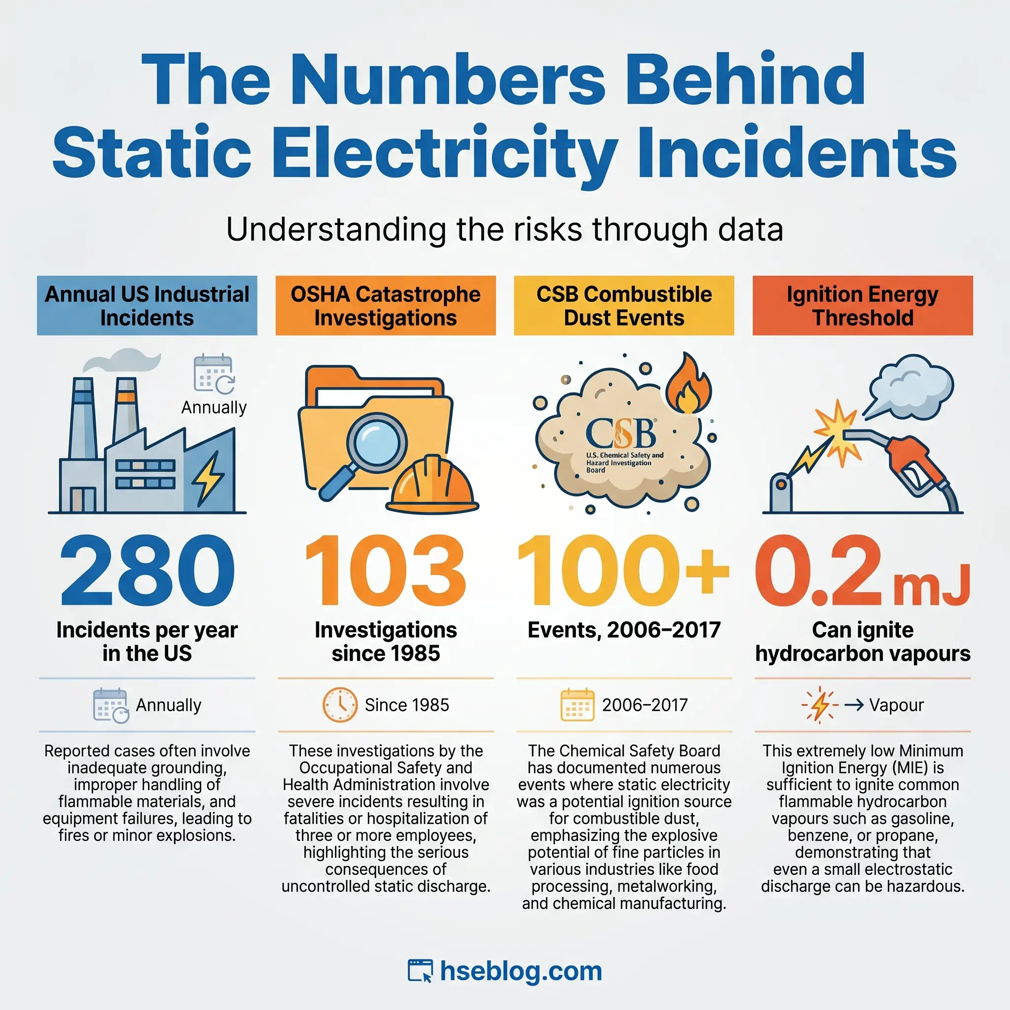
That scenario plays out in fine chemical plants, refineries, pharmaceutical sites, and grain facilities more often than most operators realise. Static electricity workplace hazards account for roughly 280 industrial incidents a year in the United States alone, and the phenomenon has been linked to 103 OSHA fatality and catastrophe investigations since the mid-1980s. This guide covers what static electricity actually is, how it generates on the job, the four distinct discharge types that matter for ignition, the hazard categories they create, and the hierarchy of controls a serious HSE programme uses to shut them down.
What is Static Electricity?
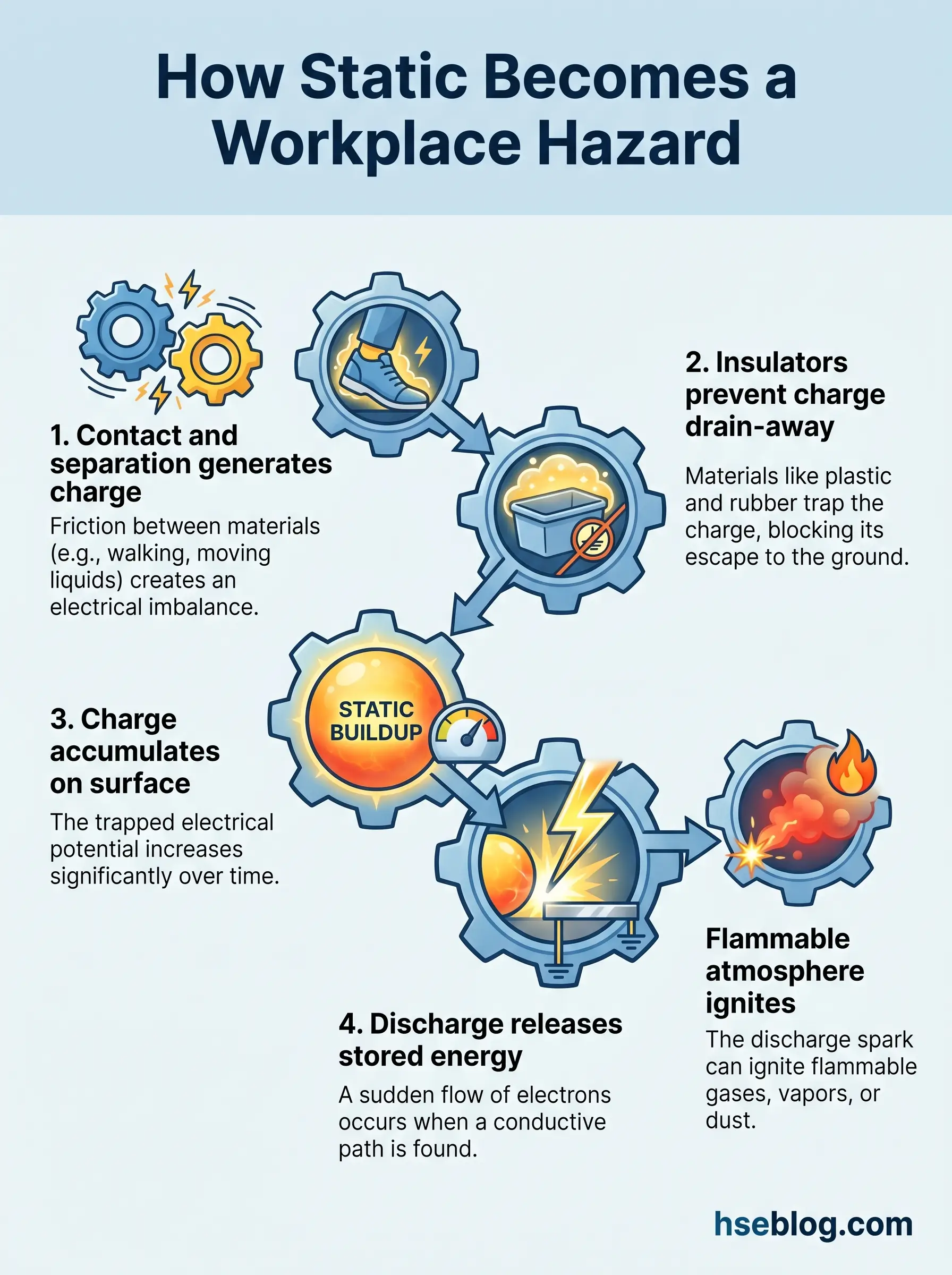
Static electricity is the accumulation of electrical charge on the surface of a material, produced when two dissimilar materials make contact and then separate. Under that contact, electrons transfer from one surface to the other along what physicists call the triboelectric series — a ranked list showing which materials give up electrons and which take them. Rubber pulls electrons from steel. Polypropylene pulls them from human skin. Whichever material ends up electron-poor carries a positive charge; its partner carries a negative one.
The phenomenon itself is ordinary — it’s the same effect that shocks you when you touch a doorknob after crossing a carpet. What makes it dangerous at work is the combination of three conditions: continuous charge generation during normal operations, the presence of insulators that prevent charge from draining away, and the frequent coexistence of flammable atmospheres or ignition-sensitive electronics in the same room.
Static electricity is not the same as current electricity. Current describes a flow of electrons through a closed circuit. Static is a stationary imbalance, held in place until a discharge path opens. A worker can carry 25,000 V on their body and feel nothing because the stored energy is only a few millijoules — but those few millijoules are enough to ignite acetone vapour ten times over.
Field definition — triboelectric effect: The transfer of electrons between two materials during contact and separation. The greater the difference in their position on the triboelectric series and the larger the contact area, the more charge is generated.
How Static Electricity is Generated in the Workplace
Walk through a working solvent transfer bay and you can almost predict where charge is accumulating — it’s a question of reading the process rather than reading a meter. Every point where two surfaces contact and separate, every fluid passing through a restriction, every powder stream falling into a drum is a charge-generation site. The list is longer than most site walks acknowledge.
Belt systems generate charge by friction between the belt and its rollers. Liquid transfer generates charge by contact between the liquid and the pipe wall, with the effect multiplying dramatically when the liquid passes through a fine filter or a partially closed valve. Powder handling is the heaviest generator of all — a pneumatic transfer line moving a granulated active pharmaceutical ingredient can produce charge densities high enough to trigger a propagating brush discharge on the silo wall.
Human movement counts too. Walking across a polyvinyl floor, sliding off a vinyl seat, pulling off a nylon jacket — all of these transfer charge onto the body. Below 30% relative humidity, that charge stays on the body long enough to find a discharge path. The combination most site teams underrate is low humidity plus insulating footwear plus a dry February shift handover near an open solvent drum.
Common industrial generation sources include:
- Liquid flow through pipes and filters — particularly low-conductivity hydrocarbons like toluene, hexane, and diesel below about 50 picosiemens per metre
- Splash filling of drums, tanks, and totes — the liquid jet, surface agitation, and mist all generate charge simultaneously
- Powder transfer and FIBC discharge — bulk bag emptying is one of the highest-charging operations in industry
- Conveyor belts, drive belts, and film unwinding — continuous contact-separation cycles
- Two-phase flow — wet steam, atomised spray, pneumatic conveying of powders with trace moisture
- Personnel movement — walking, sitting, donning and doffing garments on insulating flooring
Types of Electrostatic Discharge
Not every electrostatic discharge is the same. The word “spark” gets used loosely on site, but a spark is only one of four recognised discharge types, and treating them as interchangeable is why so many control plans miss their mark. The energy released, the geometry of the discharge, and the materials involved all shape which flammable atmospheres or electronic components a discharge can ignite or damage.
The table below sets out the four categories and what each one can do:
| Discharge Type | Typical Energy | Primary Ignition Risk | Common Scenario |
|---|---|---|---|
| Spark | Up to 10,000 mJ | Vapours, gases, and many dusts | Two ungrounded conductors — a metal funnel and a drum |
| Brush | Up to ~4 mJ | Flammable gases and vapours; rarely dusts | Charged plastic surface approached by a grounded tool |
| Corona | Below 0.1 mJ | Generally not an ignition source | Sharp earthed points dissipating charge from a cloud |
| Propagating brush | Up to several thousand mJ | Vapours AND combustible dusts | Double-layer charged insulator on a metal backing |
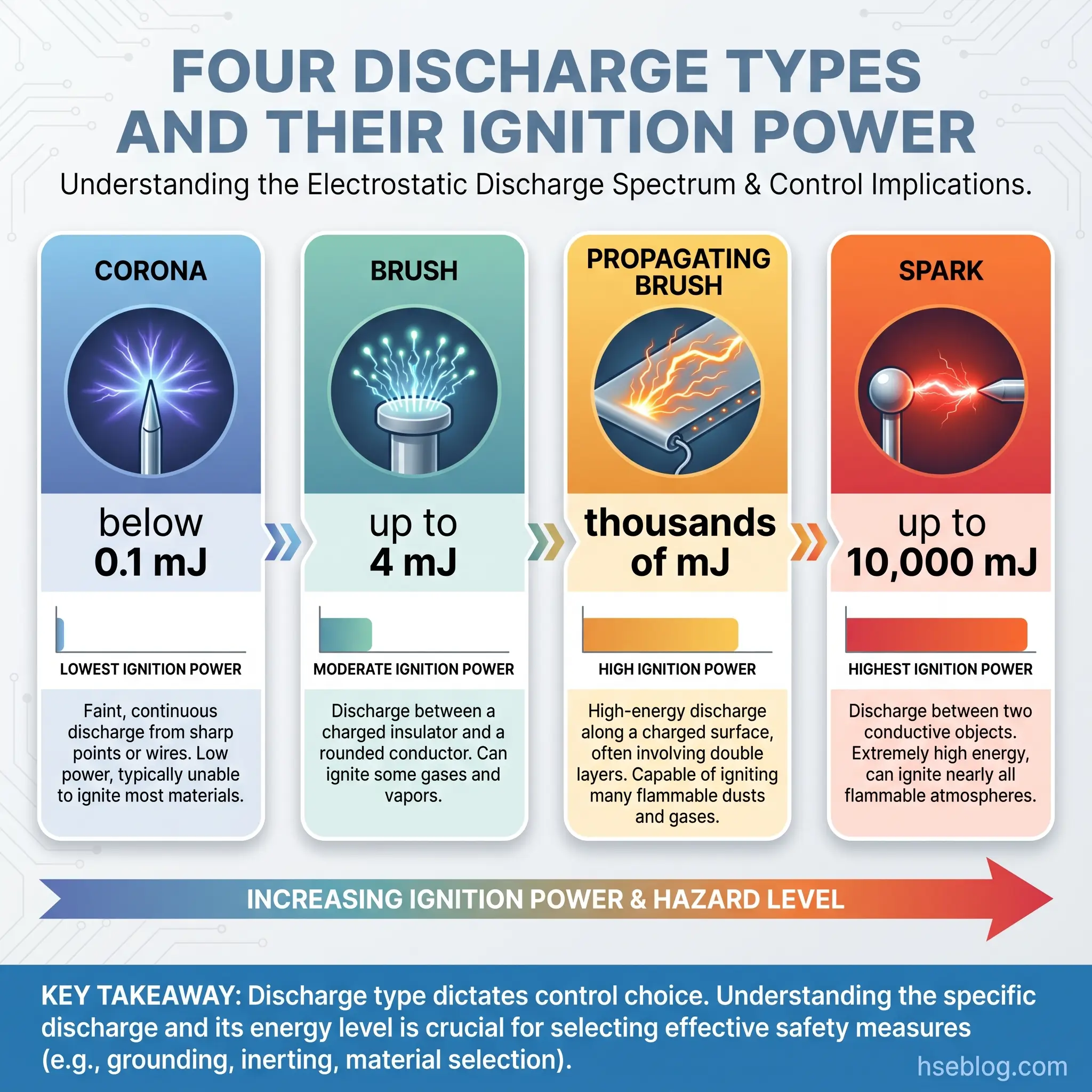
A spark is the one most people picture — a bright flash between two conductors. It carries nearly all the stored energy across the gap almost instantly, which is why it ignites the widest range of atmospheres. A brush discharge happens when a grounded conductor approaches a charged insulator; the discharge spreads over a larger area, limiting peak energy to roughly 4 mJ. That sits below the ignition threshold for most combustible dusts but well above the MIE for gases like hydrogen (0.017 mJ) or acetylene (0.02 mJ).
Corona discharges happen at sharp points and are so low-energy that engineers deliberately use them in passive ionisation bars. The dangerous outlier is the propagating brush discharge — it only forms on a double-layer insulator (typically a thin non-conductive film over a grounded conductor, or vice versa) and it can release thousands of millijoules in a single event. That is how an FIBC of the wrong classification ignites a solvent vapour cloud during discharging.
Why Static Electricity is a Serious Workplace Hazard
The numbers put the scale into perspective. U.S. fire departments respond to roughly 280 industrial incidents involving static electricity each year, and OSHA’s own fatality and catastrophe investigations name static in 103 cases between 1985 and 2018. The U.S. Chemical Safety Board documented more than 100 combustible dust incidents between 2006 and 2017, with static discharge frequently implicated as the ignition source. Behind those numbers are four very different failure modes, each requiring its own control strategy.
Fire and Explosion in Flammable Atmospheres
Three elements must align for a static-ignited fire: a charge generator, a discharge mechanism, and a flammable atmosphere within its explosive range. When the minimum ignition energy (MIE) of the atmosphere is below the discharge energy, ignition is nearly certain. For many common solvents — toluene at 0.24 mJ, hexane at 0.23 mJ, ethylene at 0.07 mJ — even a small brush discharge suffices. The workers don’t see the spark, smell the fault, or hear a warning. The first sign is the flash.
Combustible Dust Explosions
Dust clouds behave differently from vapours. Most organic and metal dusts have MIE values between 10 and 100 mJ — higher than a brush discharge can deliver, but well within reach of a spark or a propagating brush. The catastrophic scenarios — sugar refineries, wood pellet plants, aluminium polishing shops — almost always trace back to accumulated charge on an insulating surface inside a dust-laden vessel, igniting the primary cloud and then lofting layered dust into a secondary explosion.
Damage to Sensitive Electronics (ESD)
The electronics hazard runs on a completely different energy scale. Modern semiconductor devices can be damaged by discharges releasing as little as 2 to 1,000 nanojoules — millions of times less energy than the vapour ignition threshold. The Human Body Model, Machine Model, and Charged Device Model are the three standard test methods used to characterise device sensitivity. Latent damage — devices that function on the production line but fail weeks later in the field — is the quiet cost that drives the quality budget in any assembly operation.
Worker Injury from Static Shock and Secondary Accidents
Direct static shocks rarely cause injury on their own. The real risk is the involuntary reaction — the worker who jerks away from a charged drum and falls backwards off a loading platform, or releases the valve handle on a flammable hose. I have reviewed investigations where the root cause was classed as “fall from height” and the static discharge that triggered the fall was never mentioned in the final report.
High-Risk Industries and Activities
The industries where static electricity workplace hazards dominate the risk register share one feature: they handle a substance that insulates, a substance that ignites, or both. Oil and gas operations generate charge every time low-conductivity fuels flow through loading arms, tanker manifolds, and storage tank cleaning hoses. Chemical and petrochemical plants run the same risk on a smaller scale with every reactor charge, solvent transfer, and sample-point purge.
Pharmaceutical and fine chemical sites combine solvent atmospheres with powder handling across blending, drying, milling, and filling operations. Electronics manufacturing and cleanrooms face the flip side: microjoule-scale discharges that ignite nothing but destroy millions of dollars of product. Grain, flour, sugar, and feed handling facilities carry some of the highest documented static-initiated explosion losses in the industry. Printing, coating, packaging, plastic extrusion, paint manufacture, and the mining and explosives sectors round out the list.
How to Conduct a Static Electricity Risk Assessment
DSEAR Regulation 5 requires employers to assess the risks of dangerous substances, and IEC TS 60079-32-1:2013 gives the technical methodology for doing it properly. Most competitor guidance gestures at “do a risk assessment” without showing what one looks like. A structured approach makes the gaps visible.
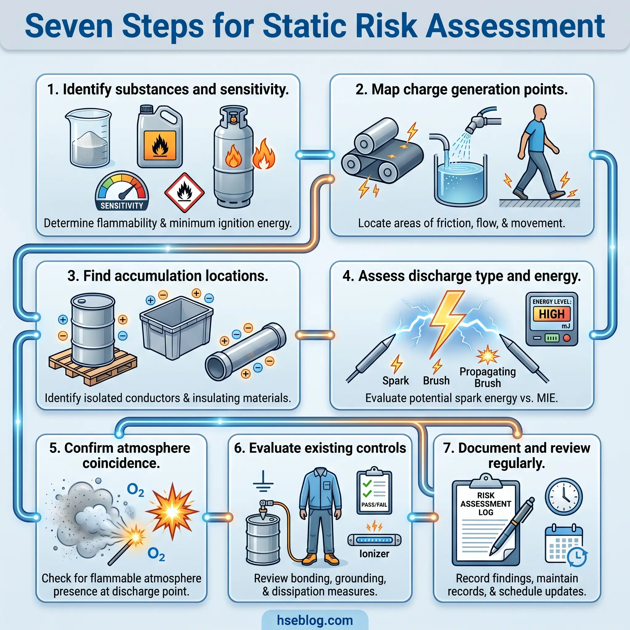
- Identify all flammable substances, combustible dusts, and ESD-sensitive items. Gather flash points, MIE values, dust explosion class, and minimum ignition temperatures. Without this baseline, no control decision is defensible.
- Map every point of charge generation. Walk the line. Every pump, filter, nozzle, belt, hose, sieve, transfer point, and FIBC station is a candidate. Don’t skip the workers — movement and clothing count.
- Identify where charge can accumulate. Look for insulating materials, ungrounded conductors, coated surfaces, and plastic components. An ungrounded metal funnel inside a plastic sleeve is a classic accumulator.
- Assess discharge potential and type. Refer back to the four categories above. A plastic drum handled by a grounded worker suggests a brush discharge. A metal funnel inside a lined vessel suggests a spark. A lined FIBC suggests a propagating brush.
- Determine whether an ignitable atmosphere exists at the same time and place. Cross-reference the hazardous area classification drawings — Zone 0, 1, 2 for gases and vapours; Zone 20, 21, 22 for dusts. Coincidence in space and time is what turns a discharge into an incident.
- Evaluate existing controls and identify gaps. Check bonding and grounding records, flow-rate SOPs, FIBC type certifications, ionisation monitoring, and humidity logs. Gaps become the action plan.
- Document and schedule review. Revisit after any process change, equipment change, humidity or seasonal shift, or reported near-miss. The 2024 Process Safety Progress papers by Ebadat and Cartwright make the case for exactly this shift — proactive recognition of pre-incident warning signs is now the benchmark, not post-incident investigation.
Controlling Static Electricity: The Hierarchy of Controls
Effective static control follows the standard hierarchy: eliminate first, engineer second, administer third, protect the worker last. Flat lists of controls don’t reflect how competent sites make decisions; the hierarchy does.
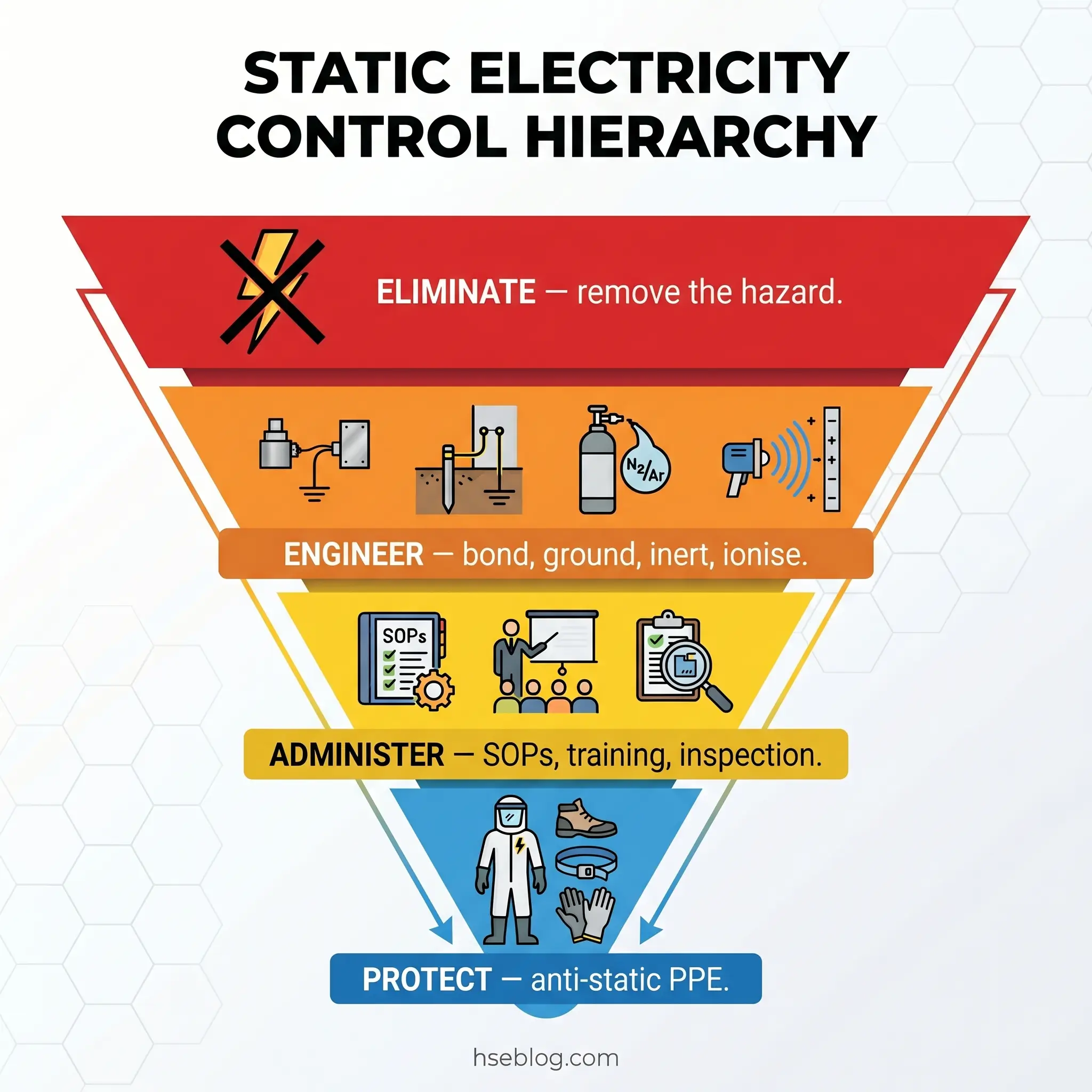
Elimination and Substitution
Every discharge that can’t happen is a discharge that can’t ignite. Substituting a non-flammable solvent removes the hazard entirely where process chemistry allows. Replacing an insulating plastic funnel with a grounded stainless-steel equivalent eliminates a major accumulator. Redesigning a splash-fill line as a bottom-fill via a dip pipe reaching within 150 millimetres of the vessel floor eliminates the most intense charge-generation mechanism in liquid transfer. Where elimination is on the table, it beats any downstream control.
Engineering Controls
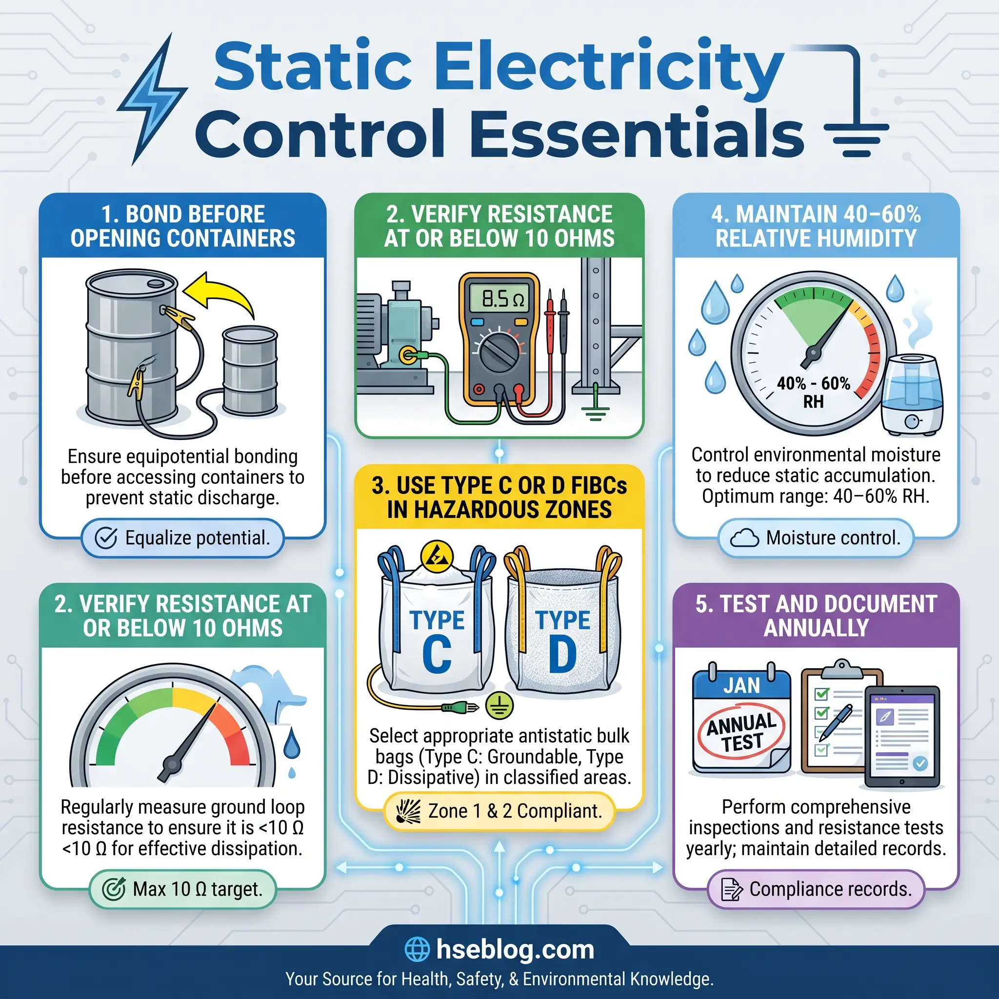
Engineering is where most of the meaningful work happens. NFPA 77 defines bonding as the connection of two or more conductive objects so they remain at the same electrical potential, and grounding as the bonding of an object (or network of bonded objects) to earth so all sit at zero potential. The two are not synonyms — a site can be bonded but ungrounded, or grounded without proper bonding between components, and both failure modes still produce sparks. When I explain this to new supervisors, I draw two metal drums connected by a cable but neither tied to earth: same potential, still capable of throwing a spark to a passing worker.
Target resistance for bonding and grounding systems is 10 ohms or less as best practice, with 25 ohms as the upper regulatory limit in most jurisdictions. I insist on resistance monitors with process interlocks at any drum or FIBC filling station handling Class I flammable liquids — the interlock stops the transfer pump if resistance rises above threshold, which is the only control a busy operator cannot defeat by habit.
Beyond bonding and grounding, engineering controls include:
- Flow velocity control — keeping initial filling velocity below 1 m/s for low-conductivity liquids until the dip pipe outlet is fully submerged, then ramping to full rate
- Relaxation time downstream of filters and pumps — typically a minimum of 30 seconds before the liquid enters a hazardous zone
- Air ionisation — active and passive bar ionisers to neutralise charge on films, webs, and powders
- Inerting — nitrogen blanketing to hold oxygen below the limiting oxygen concentration in vessels and silos
- Humidity control — maintaining 40–60% RH in susceptible areas, though never as a standalone control
- Conductive and dissipative materials — Type C and Type D FIBCs, conductive flooring, anti-static hose linings, and dissipative process components
- Bottom filling with dip pipes — eliminating splash and surface charge
Watch For: A flexible hose with a visibly conductive outer jacket but an unbonded internal helix. The external appearance passes a walk-by check; the ground path is broken. Resistance testing across the full hose assembly is the only reliable verification.
Administrative Controls
Written SOPs, training, inspection schedules, hazardous area signage, and documented incident review form the administrative layer. The rule I drill into every operator handling solvent drums is “clamp on first, clamp off last” — the bonding cable is attached before the container is opened and removed only after the container is sealed. That sequence alone prevents a large fraction of transfer incidents.
Training should cover static awareness (what it is, where it forms), PPE use (the specific footwear and garments for their zone), shock reporting (every shock is a near-miss), and bonding verification (visual, contact, and resistance checks). Annual recorded resistance testing of all bonding and grounding systems is a direct NFPA 77 recommendation, and it should generate a register that auditors can trace. CCOHS guidance on static electricity and flammable liquids endorses the same inspection discipline.
Personal Protective Equipment
PPE is the last layer, never the first. Anti-static footwear certified to EN ISO 20345 and meeting OSHA 29 CFR 1910.136(a) dissipates body charge safely to a conductive floor. Anti-static garments certified to EN 1149-5 provide equivalent control over clothing-generated charge in ATEX zones. Electronics work requires wrist straps and smocks certified to IEC 61340 standards inside an ESD-protected area.
One terminology trap catches new HSE officers regularly: anti-static footwear and electrically insulating footwear do opposite jobs. Anti-static footwear drains charge to ground through a controlled resistance (typically 100 kilohms to 100 megohms). Insulating footwear stops current flow entirely to protect against mains electrocution. Wearing insulating boots in a flammable atmosphere defeats the grounding strategy and turns the wearer into a charged conductor.
Regulatory Framework and Standards
The international regulatory map around electrostatic hazards is denser than most operators realise. A single operation may fall under OSHA, NFPA, IEC, ATEX, DSEAR, and API requirements simultaneously. The reference map below covers the core set.
| Standard / Regulation | Jurisdiction | What It Requires |
|---|---|---|
| NFPA 77 (2024 ed.) — Recommended Practice on Static Electricity | North America | Evaluation of electrostatic ignition hazards; bonding, grounding, charge dissipation, flow-rate limits, FIBC handling |
| OSHA 29 CFR 1910.106 | USA | Precautions against ignition of flammable liquid vapours, including static sources |
| OSHA 29 CFR 1910.136(a) | USA | Protective footwear where static-discharge hazard is present |
| IEC TS 60079-32-1:2013 (+2017 am.) | International | Technical guidance on electrostatic hazards in explosive atmospheres |
| ATEX Directive 2014/34/EU | EU | Equipment certification for Zones 0/1/2 and 20/21/22; prevention of dangerous electrostatic discharges |
| DSEAR 2002 | UK | Risk assessment of dangerous substances (Reg. 5); hazardous area classification (Reg. 7) |
| NFPA 70 Article 250 | USA | Grounding and bonding installation requirements |
| EN 1149-5 | EU / UK | Material and design requirements for anti-static protective clothing |
| IEC 61340-4-4 | International | Electrostatic classification of FIBCs into Types A, B, C, D |
| API RP 2003 | USA / Petroleum | Protection against ignitions from static, lightning, and stray currents |
OSHA does not adopt NFPA 77 by direct reference but uses it as the benchmark of “reasonable precautions” under the General Duty Clause. In practice, a citation against a U.S. employer who ignored NFPA 77 will cite Section 5(a)(1) of the OSH Act alongside the specific 1910 subpart. The HSE UK guidance on electricity in potentially explosive atmospheres sits alongside DSEAR as the working reference for UK sites, and the IEC and ATEX frameworks govern almost everything outside the U.S.
Inspection, Testing, and Maintenance of Static Controls
A bonding cable that looked serviceable last month can fail inspection today. Cables abrade, clamp springs weaken, paint and product build up on contact points, and connection lugs corrode. A grounding system is only as good as its last verified measurement. Visual checks are necessary but not sufficient; resistance measurement is what confirms function.
The test instrument is an ohmmeter capable of measuring from below 1 ohm to several megohms, applied across the full path from the far conductor to the earth electrode. Readings must be logged, dated, and retained. When resistance creeps above the site’s acceptance threshold, the cable, clamp, or connection gets replaced — not cleaned, not adjusted, replaced.
Audit Point: Alligator-only clamps fitted to painted drum surfaces. The clamp looks properly attached; the paint layer is a perfect insulator. Auditors read “ground cable connected” in the log and never test continuity. Insist on stainless-steel contact points with penetrating teeth and a documented resistance reading for every first use of the day.
A minimum inspection and testing programme includes:
- Visual inspection of cables, clamps, and connection points before each use
- Resistance measurement at commissioning and after any repair
- Annual recorded resistance testing of permanent installations per NFPA 77
- Immediate replacement of damaged, corroded, or kinked cables
- Self-monitoring bonding systems with process interlocks where operator turnover or shift-work makes pre-use checks unreliable
What To Do After a Static-Related Incident or Near-Miss
A reported static shock is not a joke to file and forget. It is evidence that charge is accumulating somewhere it shouldn’t, and the next event may not be a shock. Treat every reported discharge — even a minor one — as a near-miss warranting structured investigation.
The first questions I ask when a shock is reported: Did anything change before the event — a different solvent grade, a new batch of FIBCs, a different floor cleaning agent, a recent bonding repair? What was the humidity that shift? Was the worker wearing their issued anti-static footwear, and was it tested? Has the grounding resistance for that station been measured recently? Each question points at a specific failure mode, and the answers should update the risk assessment and control plan.
Reportable incidents fall under RIDDOR in the UK, OSHA recordkeeping in the U.S., and equivalent regimes elsewhere. A static shock by itself is usually not reportable, but a resulting fall, fire, or damage crosses the threshold. When in doubt, report and investigate — the paperwork is always cheaper than the next incident.
Frequently Asked Questions
Conclusion
The industry’s relationship with static electricity workplace hazards is shifting. For decades, the default model was reactive — investigate after the fire, tighten the controls, retrain the crew. The 2024 Process Safety Progress papers by Ebadat and Cartwright make the case that the mature model is proactive: identify the early warning signs of electrostatic trouble (unexplained shocks, unusual product behaviour, humidity drops, new material grades) and fold them into process hazard analysis before they graduate into incidents.
The 2024 edition of NFPA 77 reinforces that direction, and IEC 60079-32-1 has been pointing the same way since 2013. Expect the next decade to bring more self-monitoring bonding systems with process interlocks, more routine integration of electrostatic assessment into HAZOP studies, and more emphasis on FIBC type verification at goods-inwards rather than at the filling line. Expect regulators to ask harder questions about pre-incident indicators and documented response.
For HSE professionals, the working brief is unchanged. Know the physics. Map the generation points. Classify the discharges. Match controls to the hierarchy. Verify the system by measurement, not by walk-by. The tools for doing that are better than they have ever been, and the regulatory framework backs every step. Static electricity is one of the few remaining industrial hazards where competent engineering almost always wins.