
Toluene has a flash point of 4°C. At room temperature, an open container doesn’t just release vapour — it generates a flammable atmosphere that sits heavier than air, pooling in trenches, pits, and low points across the floor. The vapour is invisible. It carries no colour. At concentrations between 1.1% and 7.1% by volume, a single spark from an uncertified motor starter or an overheated cable gland is enough to turn a routine batch operation into a fireball that travels faster than anyone can react to.
That is the scenario hazardous area classification exists to prevent. Across the chemical, oil and gas, pharmaceutical, food processing, and mining industries, explosive atmospheres are not hypothetical — they are an engineered certainty of normal operations. Workplace explosions claimed 66 lives in the United States in 2023 alone, representing 1.2% of all fatal work injuries that year. Between 1980 and 2017, combustible dust incidents in the United States killed 185 workers and injured over 1,000 more. This article breaks down the classification frameworks, the material science behind them, the step-by-step process for conducting a classification study, and the equipment selection decisions that flow from every zone boundary drawn on a facility plot plan.
What Is Hazardous Area Classification and Why Does It Matter?
Hazardous area classification — often shortened to HAC — is the risk assessment methodology used to identify every location within a facility where an explosive atmosphere could form, and to categorize each of those locations by the probability and duration of that atmosphere’s presence. The output of a HAC study is not a report filed in a drawer. It is the foundational document that dictates what equipment can be installed, how electrical systems must be designed, and which maintenance and operational procedures apply to every square metre of classified space.
The concept rests on the fire and explosion triangle: fuel, oxygen, and an ignition source. In most industrial environments, removing oxygen is impractical — we work in open air. Eliminating the fuel entirely is often impossible when that fuel is the raw material, intermediate, or by-product of the process itself. HAC targets the third leg — ignition source control — by ensuring that every electrical and non-electrical energy source within a classified area is designed, certified, and maintained to be incapable of providing enough energy to ignite the specific atmosphere present.
This makes HAC the first step in any facility design or modification involving flammable or combustible materials. Without it, there is no rational basis for specifying junction boxes, lighting, motors, instrumentation, or even mobile phones. The industries where HAC is mandatory span upstream oil and gas production, midstream pipeline terminals, downstream refining, chemical manufacturing, pharmaceutical production, food and grain processing, mining, paint and coatings, wastewater treatment, and the rapidly expanding hydrogen economy. A solvent recovery unit in a pharmaceutical plant and a grain elevator in a flour mill face different substances but the same fundamental question: where can an explosive atmosphere exist, and for how long?
The Explosion Triangle: Understanding What Creates an Explosive Atmosphere
Every explosion requires three simultaneous conditions. Remove any one of them and the event cannot occur. In a chemical processing facility running multiple solvent-based reactions, these three conditions deserve precise technical understanding — not textbook summaries.
The first element is fuel. In HAC terms, fuel exists in four forms: flammable gases (methane, hydrogen, acetylene), flammable vapours (toluene vapour, acetone vapour, hexane vapour), flammable mists (atomised liquid hydrocarbons released under pressure from leaking flanges), and combustible dusts (pharmaceutical powders, grain dust, metal fines, sugar). Each fuel type has properties that directly influence classification decisions.
Flash point determines the lowest temperature at which a liquid produces enough vapour to form a flammable mixture. Auto-ignition temperature (AIT) defines the minimum temperature at which a substance ignites without an external spark or flame — this drives the temperature class of equipment permitted in the zone. The Lower Explosive Limit (LEL) and Upper Explosive Limit (UEL) define the flammable range, and substances with wide ranges — hydrogen’s 4% to 74%, for instance — present far greater classification challenges than narrow-range materials. Minimum Ignition Energy (MIE) dictates how easily an atmosphere ignites; hydrogen’s MIE is roughly 0.017 millijoules, making static discharge a credible ignition source. Maximum Experimental Safe Gap (MESG) determines which equipment group a substance falls into, governing enclosure design.
The second element is oxygen. Ambient air at 20.9% oxygen is the default oxidiser. In enclosed systems — reactor vessels, dryer drums, storage tanks — inert gas blanketing can reduce oxygen below the Limiting Oxygen Concentration (LOC), eliminating explosion potential inside the vessel. But HAC addresses the surrounding area, where ambient oxygen is present and cannot be controlled.
The third element is the ignition source. HAC exists to ensure this leg is never completed. Electrical arcs, hot surfaces, static discharge, mechanical friction, adiabatic compression — all are credible ignition sources that the classification process must account for.
| Property | What It Determines | Example |
|---|---|---|
| Flash Point | Whether vapour forms at operating temperature | Toluene: 4°C |
| Auto-Ignition Temperature | Equipment temperature class (T-class) | Diethyl ether: 160°C |
| LEL / UEL | Width of flammable range | Hydrogen: 4%–74% |
| Minimum Ignition Energy | Sensitivity to static and weak sparks | Hydrogen: 0.017 mJ |
| MESG | Equipment group classification | Acetylene: 0.25 mm |
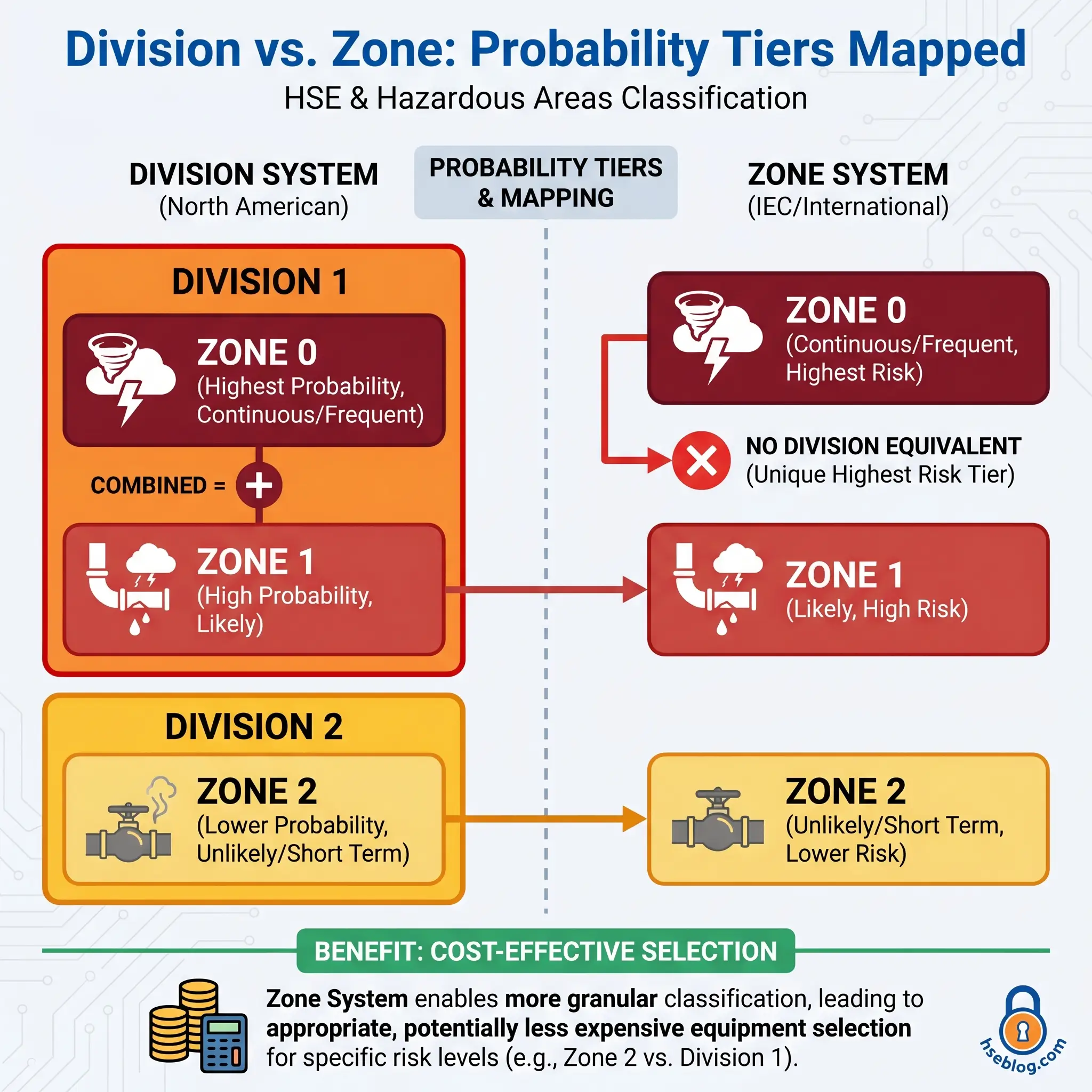
The Two Classification Systems: Class/Division vs. Zone
Two globally recognised frameworks exist for hazardous area classification. Both answer the same question — what is the probability of an explosive atmosphere existing at a given location? — but they structure the answer differently.
The North American system, codified in NEC (NFPA 70) Article 500, uses three Classes (defining material type), two Divisions (defining probability), and lettered Groups (defining material properties). This system has been the standard in the United States and Canada for decades. Its two-tier probability model — Division 1 for normal operating conditions, Division 2 for abnormal conditions only — is straightforward but coarse.
The international system, based on IEC 60079-10-1 and mandated across Europe under ATEX Directive 1999/92/EC, uses a Zone-based probability scale. For gases and vapours: Zone 0, Zone 1, and Zone 2. For combustible dusts: Zone 20, Zone 21, and Zone 22. This three-tier model separates continuous presence (Zone 0/20) from occasional presence during normal operations (Zone 1/21) and presence only during abnormal conditions (Zone 2/22).
The Zone system was adopted into the NEC as an accepted alternative through Articles 505 (gases) and 506 (dusts). Canada’s CEC has required Zone classification for all new installations since 1998. The practical advantage is granularity — Zone 0 identifies locations where the most stringent (and expensive) equipment categories are genuinely needed, while the broader Division 1 designation covers both Zone 0 and Zone 1 equivalents, often resulting in unnecessarily conservative equipment specifications.
During a plant expansion project, I watched the engineering team’s initial design specify Division 1 equipment throughout an entire reactor hall. When we reclassified using the Zone system, only the immediate vicinity of the reactor vent and sample points required Zone 1-equivalent protection. The remaining floor area dropped to Zone 2. The equipment cost savings exceeded the classification study fee many times over.
| Feature | Class/Division (NEC 500) | Zone (IEC 60079 / NEC 505–506) |
|---|---|---|
| Probability tiers | 2 (Division 1, Division 2) | 3 (Zone 0/1/2 or 20/21/22) |
| Continuous hazard distinction | No separate tier | Zone 0 / Zone 20 |
| Primary regions | USA (traditional), Canada (legacy) | Europe, Asia, Oceania, global new-build |
| Equipment cost impact | Higher (broader Div 1 scope) | Lower (granular zone matching) |
| Regulatory basis | NEC Article 500, NFPA 497/499 | IEC 60079-10-1/2, ATEX 1999/92/EC |
Classes Explained: Class I, Class II, and Class III
Under the NEC system, the Class designation identifies what type of hazardous material is present. It says nothing about probability — that is the Division’s role. Three Classes cover the full spectrum of flammable and combustible materials encountered in industry.
Class I addresses locations where flammable gases or vapours may be present in sufficient quantities to produce an explosive atmosphere. Refineries processing crude oil, paint spray booths using solvent-based coatings, fuel loading terminals, and chemical reactor areas all fall under Class I. The substances range from light hydrocarbons like methane to heavier solvents like xylene.
Class II covers locations where combustible dust may be present. Grain elevators, coal preparation plants, pharmaceutical tableting suites, metal powder processing, and sugar milling operations are Class II environments. Combustible dust explosions are often more destructive than gas explosions because a primary blast can dislodge accumulated dust from surfaces, triggering a secondary explosion of far greater magnitude.
Class III applies to locations where ignitable fibres or flyings are handled or manufactured but are unlikely to be suspended in air in sufficient quantities to form an explosive atmosphere. Textile mills processing cotton or synthetic fibres, paper mills, and woodworking facilities fall here. The Zone system does not include a direct Class III equivalent — these materials are typically assessed under the dust zones (20/21/22) where suspension is possible, or excluded from classification where it is not.
Divisions Explained: Division 1 vs. Division 2
Divisions indicate when the explosive atmosphere exists relative to normal operations. The distinction is not academic — it directly determines the protection level of every piece of equipment permitted in that space.
- Division 1 applies where the hazardous atmosphere exists under normal operating conditions. This includes locations where flammable concentrations are present continuously or intermittently during routine operations, where equipment breakdown or faulty operation could simultaneously release flammable material and provide an ignition source, and where maintenance or repair activities regularly expose flammable concentrations. An open-top solvent dip tank, the interior of a paint spray booth during operation, and the area immediately surrounding a reactor manway opened for charging — all are Division 1.
- Division 2 applies where the hazardous atmosphere exists only under abnormal conditions — equipment failure, accidental rupture, or unusual operating events. Flammable materials are handled in closed containers, closed systems, or are prevented from accumulating by adequate ventilation. A sealed drum storage warehouse with mechanical ventilation, the area around a flanged piping system where leaks occur only on gasket failure, and a well-ventilated laboratory fume hood exterior are Division 2 examples.
The critical judgement call sits at the boundary. A colleague once described Division 2 as “the zone where you trust your maintenance programme.” If that programme fails — if the gasket isn’t replaced on schedule, if the ventilation fan trips and nobody notices — Division 2 becomes Division 1 in practice, with Division 2 equipment still installed.
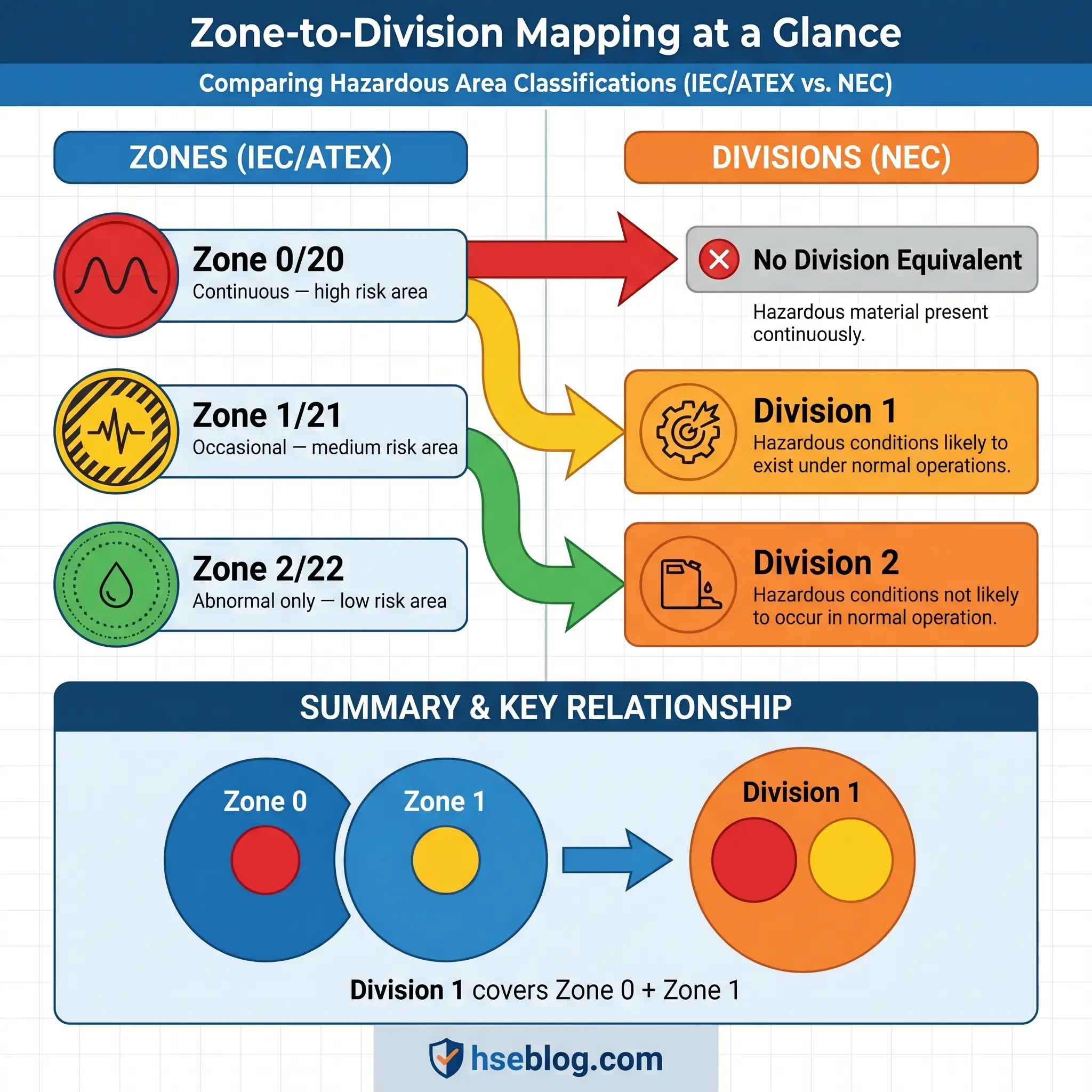
Zones Explained: Zone 0, 1, 2 (Gases) and Zone 20, 21, 22 (Dusts)
The Zone system provides the probability granularity that the Division system lacks. Six zone designations cover both gas/vapour and dust atmospheres, each with defined probability criteria.
- Zone 0 (gases) and Zone 20 (dusts) designate locations where an explosive atmosphere is present continuously, for long periods, or frequently. The interior of a storage tank containing a volatile liquid above its flash point, the inside of a powder hopper, or the headspace of a process vessel during normal operation — these are Zone 0 or Zone 20. Equipment installed here must offer the highest protection level. In practice, Zone 0 areas are kept as small as physically possible through design.
- Zone 1 (gases) and Zone 21 (dusts) designate locations where an explosive atmosphere is likely to occur occasionally during normal operations. The immediate vicinity of a fill point, the area around a frequently opened reactor manway, or the zone surrounding a dust bag-filter discharge — these are Zone 1 or Zone 21.
- Zone 2 (gases) and Zone 22 (dusts) designate locations where an explosive atmosphere is not expected during normal operations and, if it occurs, persists only briefly. These are abnormal-condition zones — gasket failures, relief valve lifts, accidental spills. Adequately ventilated areas surrounding closed process systems typically classify as Zone 2.
IEC 60079-10-1:2020 introduced the Zone 2 NE concept — “negligible extent.” Where the calculated zone is so small that any ignition would have negligible consequences, the location can be treated as non-hazardous for practical equipment selection purposes. This refined approach, part of the third edition’s updated ventilation assessment methodology, represents a significant step forward in proportionate risk management. Industry is still in the process of adopting these updated calculation methods, making Zone 2 NE a current point of practice discussion among classification specialists.
The mapping between systems is straightforward but asymmetric: Division 1 encompasses both Zone 0 and Zone 1; Division 2 maps to Zone 2. There is no Division equivalent for Zone 0 alone, which is precisely why the Zone system enables more targeted equipment specification.
Groups: Classifying the Hazardous Material
Within each Class or Zone, materials are further subdivided into Groups based on their ignition characteristics — specifically, auto-ignition temperature, MESG, and minimum ignition current (MIC) ratio. Equipment must be certified for the specific Group of the substance present.
Under the NEC system, gases and vapours are classified into Groups A through D, while dusts fall into Groups E through G.
| NEC Group | Material Type | Example Substances | IEC Equivalent |
|---|---|---|---|
| A | Gases with very small MESG | Acetylene | IIC |
| B | Gases with small MESG | Hydrogen, butadiene | IIC |
| C | Gases with moderate MESG | Ethylene, carbon monoxide | IIB |
| D | Gases with larger MESG | Propane, methane, toluene | IIA |
| E | Conductive metal dusts | Aluminium, magnesium | IIIC |
| F | Carbonaceous dusts | Coal dust, carbon black | IIIB |
| G | Non-conductive organic dusts | Grain, flour, wood, sugar | IIIA |
The IEC system uses Group I exclusively for mining applications (firedamp/methane), Group II for surface industries with gas hazards (subdivided IIA, IIB, IIC by increasing ignition sensitivity), and Group III for dust hazards (IIIA for combustible flyings, IIIB for non-conductive dusts, IIIC for conductive dusts).
A Group IIC/A–B rating is the most onerous. Equipment certified for Group IIC can be used in IIA and IIB atmospheres, but not vice versa. This hierarchy matters when multiple substances are present — the most easily ignited substance dictates the required Group rating.
Temperature Classification and Auto-Ignition Temperature
Every substance that can form an explosive atmosphere has an auto-ignition temperature — the minimum temperature at which it will ignite without a spark, flame, or other external ignition source. The temperature classification system ensures that no equipment surface within a hazardous area ever reaches this threshold.
Both the IEC and NEC systems use a T-class scale from T1 through T6, with T1 being the least restrictive and T6 the most.
| T-Class | Maximum Surface Temperature | Example Substance (AIT) |
|---|---|---|
| T1 | 450°C | Methane (595°C), Acetone (465°C) |
| T2 | 300°C | Butane (287°C — requires T3), Ethanol (363°C) |
| T3 | 200°C | Gasoline (280°C), Hexane (225°C) |
| T4 | 135°C | Acetaldehyde (175°C), Diethyl ether (160°C) |
| T5 | 100°C | — |
| T6 | 85°C | Carbon disulphide (90°C) |
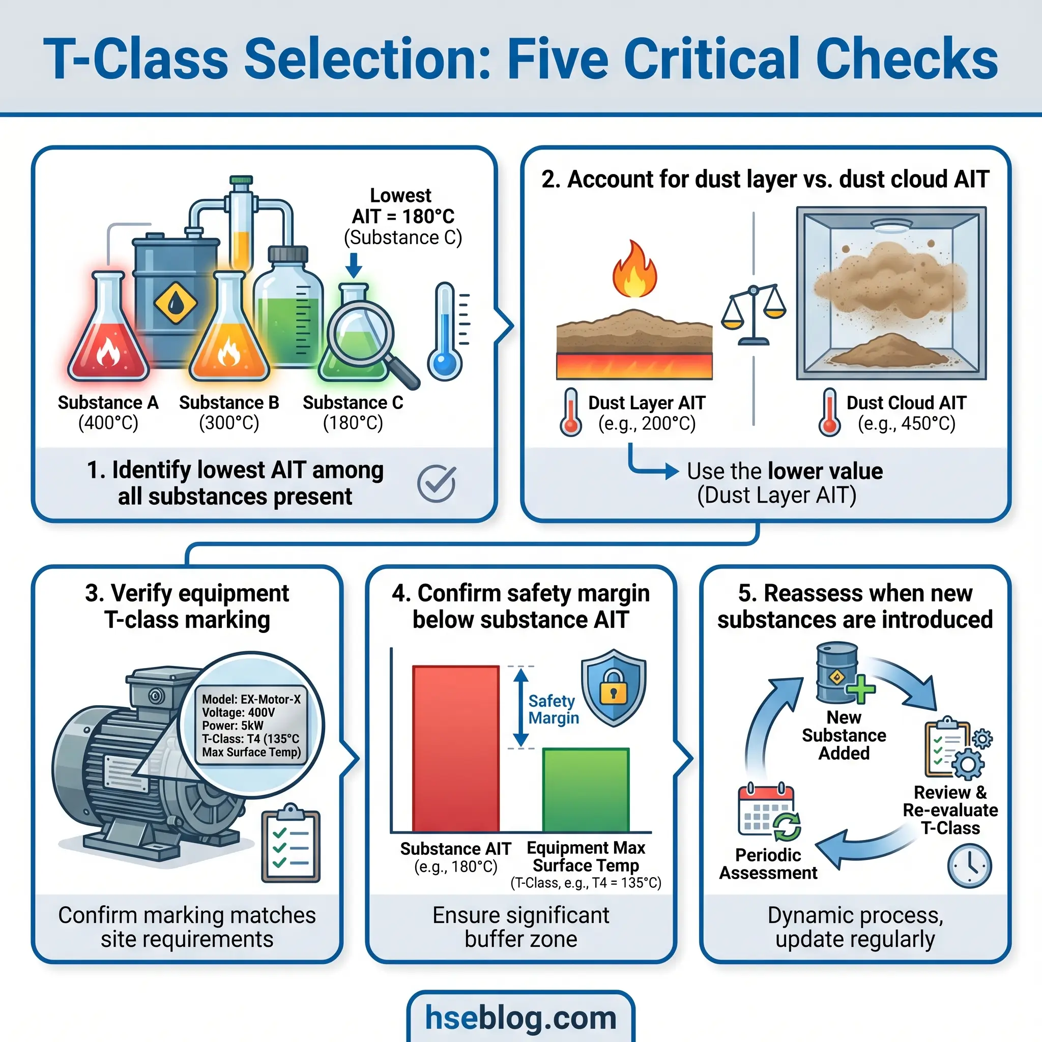
Equipment marked T3 guarantees its maximum surface temperature will never exceed 200°C. If the hazardous substance present has an AIT of 225°C, T3 equipment provides a sufficient safety margin. If multiple substances are present — common in chemical processing where solvents, intermediates, and cleaning agents coexist — the substance with the lowest AIT dictates the required T-class.
For combustible dusts, the analysis is more complex. Dust cloud AIT and dust layer AIT differ, and layer ignition temperature decreases as layer thickness increases. A 5 mm dust layer on a motor housing ignites at a lower temperature than the same dust suspended in air. This is why housekeeping — preventing dust accumulation on hot surfaces — is as critical as equipment certification in dust-classified areas.
Watch For: Dust layer accumulation on lighting fixtures, cable trays, and motor housings. A surface running well below the dust cloud AIT can still ignite a 12 mm layer. Check layer temperatures against IEC 60079-14 requirements, not just cloud AIT values.
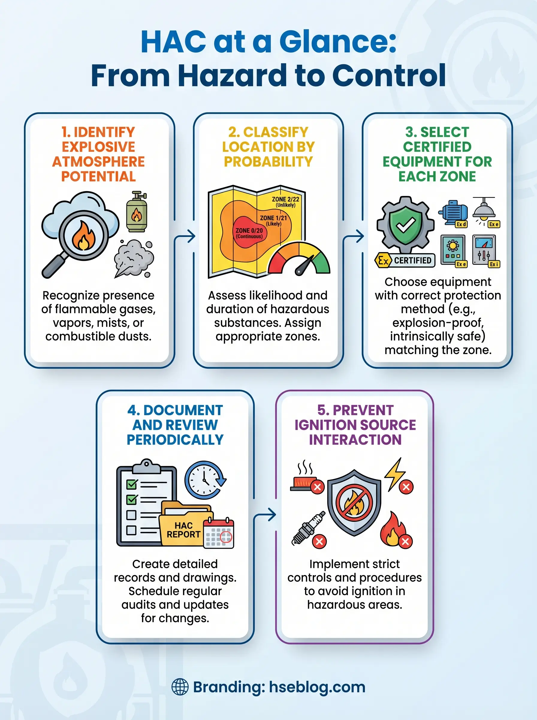
How to Conduct a Hazardous Area Classification Study
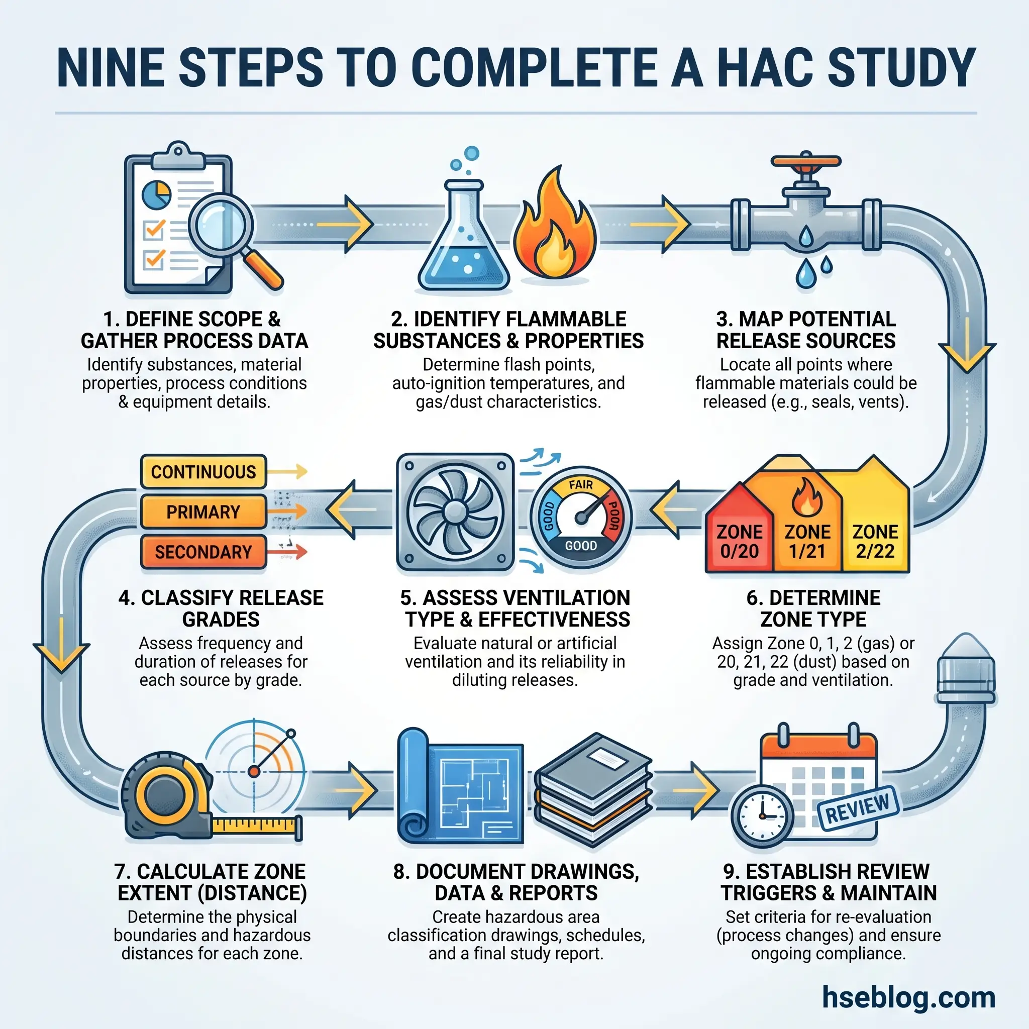
This is where theory meets engineering practice. A HAC study is not a desk exercise performed from a process flow diagram alone — it requires physical verification of every potential release source, ventilation condition, and material property. The methodology draws from IEC 60079-10-1:2020 for gas atmospheres and IEC 60079-10-2:2015 for dust atmospheres, supported by NFPA 497 and NFPA 499 in North American jurisdictions.
The following steps outline the workflow from data collection through to documentation and periodic review.
- Identify all flammable and combustible substances. Catalogue every raw material, process intermediate, by-product, waste stream, and cleaning agent present on site. Omitting a substance — such as a cleaning solvent used only during turnaround — is one of the most common classification errors. I once reviewed a classification study for a reactor suite that omitted the isopropanol used for equipment wipe-down between batches. The IPA had a flash point of 12°C and was used in open containers directly beside Zone 2-rated electrical panels.
- Determine material properties. For each substance, obtain flash point, AIT, LEL, UEL, vapour density (relative to air), MIE, MESG, and MIC ratio. Safety Data Sheets provide starting data, but published reference sources like NFPA 497 Annex B or IEC 60079-20-1 should be used for classification-grade values.
- Identify sources of release. A source of release is any point where flammable material can escape into the atmosphere. IEC 60079-10-1 grades these by frequency: continuous grade (release is continuous or expected for long periods — open liquid surfaces, vents), primary grade (release expected periodically during normal operations — pump seals, sample points, fill connections), and secondary grade (release not expected during normal operation — flange gaskets, relief valves, corroded fittings).
- Assess ventilation. Ventilation is the single most influential factor in determining zone type and extent. IEC 60079-10-1 evaluates three ventilation parameters: type (natural or artificial), availability (good, fair, or poor — reflecting uptime reliability), and effectiveness (high, medium, or low dilution capability). A well-ventilated outdoor installation can reduce zone extents dramatically compared to the same release source inside an enclosed building with poor air movement.
- Determine zone type. Using the release grade and ventilation assessment, apply the zone determination matrix from IEC 60079-10-1 (Table D.1 in the standard’s informative annexes). A continuous-grade release with adequate ventilation typically produces Zone 1 in the immediate vicinity. A secondary-grade release with good ventilation may produce Zone 2 or even Zone 2 NE.
- Determine zone extent. This is the spatial boundary of each zone — how far from the release source the explosive atmosphere can credibly extend. IEC 60079-10-1 provides calculation methods based on release rate, ventilation velocity, vapour density, and LEL. Computational fluid dynamics (CFD) modelling is used for complex geometries, but simplified calculations cover most standard configurations.
- Create area classification drawings. The study output must include plan views and elevation (section) views showing all zone boundaries overlaid on facility layout drawings. Every zone must be clearly labelled with its designation, the substance(s) driving the classification, the equipment group, and the required temperature class.
- Compile documentation. The complete classification package includes substance data sheets, release source identification, ventilation assessments, zone determination rationale, calculation records, reference standards used, and the classification drawings. This package forms the basis of the Explosion Protection Document required under ATEX 1999/92/EC and UK DSEAR.
- Establish a review cycle. Classification is not permanent. DSEAR mandates review every five years or whenever processes, materials, or ventilation change. OSHA requires documentation of all classified areas and ongoing compliance verification under 29 CFR 1910.307. Every Management of Change (MOC) procedure should include HAC review as a standard gate.
Audit Point: During compliance audits, inspectors frequently find that classification drawings have not been updated after process modifications. If your reactor suite was reclassified three years ago but a new solvent was introduced last year, the existing classification may be invalid — and every piece of equipment installed based on it is potentially non-compliant.
Equipment Selection and Protection Methods for Hazardous Areas
Once zone boundaries are established, every piece of electrical and mechanical equipment within those boundaries must carry certification appropriate to the zone, group, and temperature class. The principle is straightforward: match the equipment’s protection level to the zone’s hazard probability.
The IEC system defines Equipment Protection Levels (EPLs): Ga (very high protection, suitable for Zone 0), Gb (high protection, Zone 1), and Gc (enhanced protection, Zone 2) for gases. For dusts, Da, Db, and Dc serve the same hierarchy. ATEX mirrors this through Equipment Categories: Category 1 for Zone 0/20, Category 2 for Zone 1/21, and Category 3 for Zone 2/22.
Several protection concepts achieve these levels through fundamentally different engineering approaches.
- Flameproof enclosures (Ex d): The enclosure is strong enough to contain an internal explosion and cool the escaping gases through engineered flame paths so they cannot ignite the surrounding atmosphere. Common for motors, switchgear, and junction boxes in Zone 1.
- Intrinsic safety (Ex i): Electrical energy is limited — through barriers and circuit design — to levels below the minimum ignition energy of the atmosphere. No explosion occurs because ignition is physically impossible. This is the preferred protection method for Zone 0 instrumentation: transmitters, thermocouples, level sensors.
- Pressurised/purged enclosures (Ex p): Positive pressure of clean air or inert gas prevents the ingress of flammable atmosphere into the enclosure. Used for analysers, large control panels, and variable-speed drives in Zone 1 and Zone 2.
- Increased safety (Ex e): Construction eliminates arcing, sparking, and excessive temperatures through enhanced design margins on terminals, winding insulation, and conductor connections. Common for junction boxes, terminal housings, and certain motor types in Zone 1.
- Non-sparking (Ex n): Equipment designed not to produce sparks, arcs, or hot surfaces during normal operation. Suitable for Zone 2 only — it does not provide protection against fault conditions.
- Encapsulation (Ex m), oil immersion (Ex o), and powder filling (Ex q): Specialised methods enclosing ignition-capable components in compound, oil, or quartz powder respectively. Each has specific zone applicability.
“What’s the difference between explosion-proof and intrinsically safe?” — I’ve been asked this question by site electricians more times than I can count. The answer I give: explosion-proof assumes the explosion will happen inside the enclosure and contains it. Intrinsically safe ensures the explosion can never start. One builds a stronger box. The other removes the match.
| Protection Concept | Code | Principle | Suitable Zones (Gas) |
|---|---|---|---|
| Flameproof | Ex d | Contains internal explosion | 1, 2 |
| Intrinsic safety | Ex i | Limits energy below ignition | 0, 1, 2 (ia); 1, 2 (ib) |
| Pressurised | Ex p | Prevents gas ingress | 1, 2 |
| Increased safety | Ex e | Eliminates arcing/sparking | 1, 2 |
| Non-sparking | Ex n | Normal operation safe only | 2 |
| Encapsulation | Ex m | Seals ignition source in compound | 0, 1, 2 |
Understanding ATEX and IECEx Certification and Marking
Two certification frameworks govern equipment placed into hazardous areas globally. Understanding how to read equipment markings is a practical skill that many practitioners lack — and misreading a nameplate can result in installing the wrong equipment in a classified zone.
ATEX Directive 2014/34/EU is mandatory for equipment sold within the European Union for use in potentially explosive atmospheres. Its companion, ATEX Directive 1999/92/EC (often called ATEX 137), places obligations on employers to classify workplaces, assess explosion risks, and select equipment of the appropriate category for each zone.
The IECEx system is a voluntary international certification scheme based on the IEC 60079 series. It does not replace national regulations but facilitates global trade by providing a single set of test reports and certificates recognised across participating countries, eliminating duplicative testing.
A typical ATEX equipment marking reads: Ex II 2G Ex d IIB T4 Gb. Decoded: the Ex hexagon symbol confirms ATEX compliance; Group II indicates surface industry (not mining); Category 2 means suitable for Zone 1; G denotes gas atmosphere; Ex d specifies flameproof protection; IIB is the gas group; T4 is the temperature class (max 135°C); and Gb confirms the Equipment Protection Level.
In North America, equipment carries listings from nationally recognised testing laboratories — UL, FM Global, or CSA — certifying compliance with NEC requirements. The marking system differs in format but serves the identical purpose: confirming that equipment is certified for the specific Class, Division (or Zone), Group, and temperature code of its installed location.
Field Test: Pick any piece of Ex-certified equipment on your site and read its nameplate. Can you identify the protection type, gas group, temperature class, and EPL? If any of those parameters do not match the classification of the area where the equipment is installed, you have a compliance gap that needs immediate attention.
Key Regulatory Standards and Codes of Practice
The regulatory landscape for hazardous area classification spans international standards, regional directives, and national codes. The following references form the core framework practitioners must navigate.
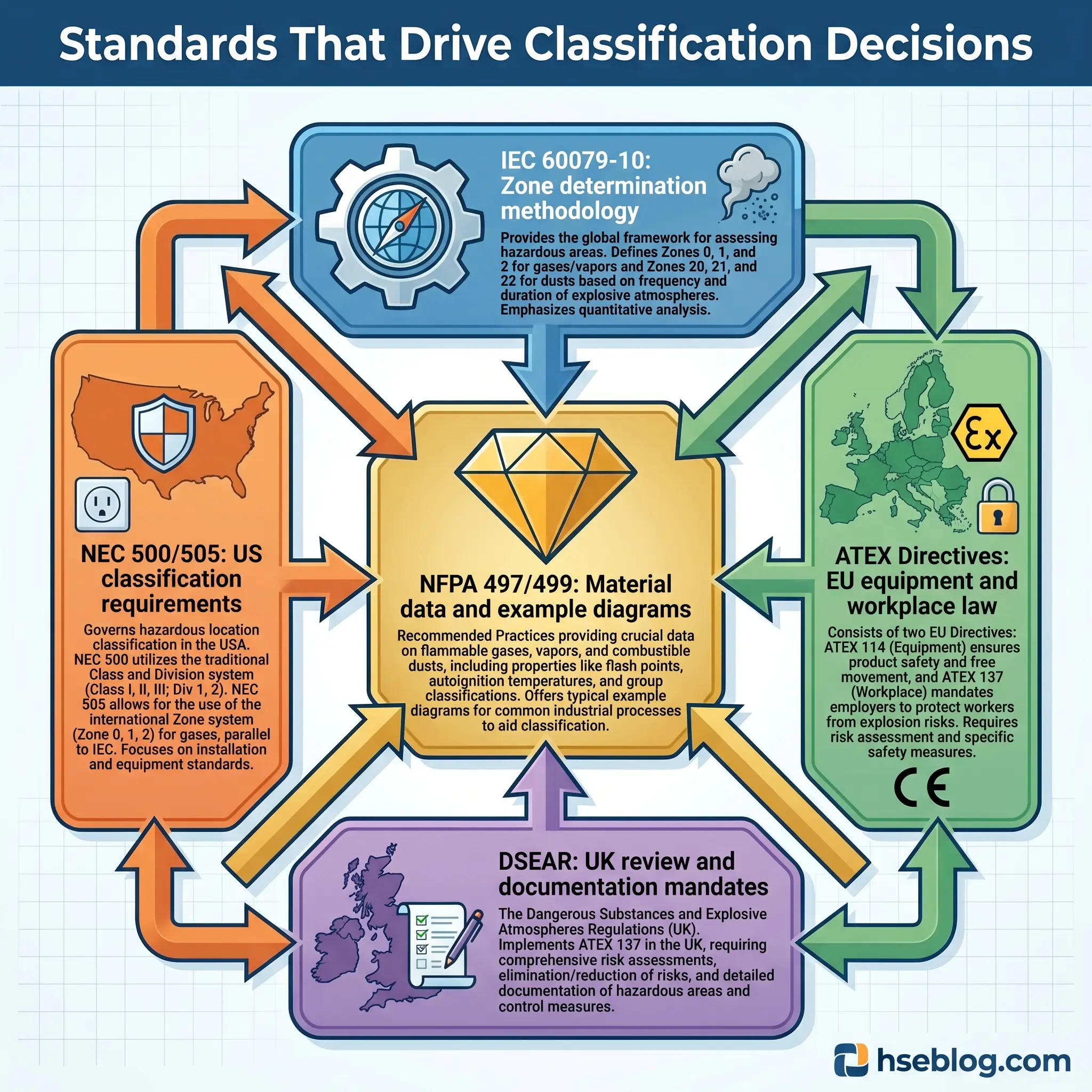
- NEC (NFPA 70) Articles 500–506 establish both the Class/Division and Zone classification systems for electrical installations in the United States. Article 500 codifies the traditional Class/Division framework; Articles 505 and 506 provide the Zone alternative aligned with international practice.
- NFPA 497 and NFPA 499 are recommended practices for classifying Class I (gas/vapour) and Class II (combustible dust) hazardous locations, respectively. They include material property tables, example classification diagrams, and recommended zone extents for common equipment configurations.
- IEC 60079-10-1:2020 is the current international standard for classifying explosive gas atmospheres. Its third edition introduced refined ventilation assessment methods and the Zone 2 NE concept. IEC 60079-10-2:2015 is the companion standard for combustible dust classification, defining Zones 20, 21, and 22.
- ATEX 2014/34/EU (Equipment Directive) mandates certification for equipment entering the EU market. ATEX 1999/92/EC (Workplace Directive) mandates employer obligations: risk assessment, area classification, equipment selection, and documentation.
- OSHA 29 CFR 1910.307 requires employers to classify hazardous locations, document all classified areas, and ensure equipment is approved for its location. All areas designated after August 13, 2007, must be documented and the documentation must be accessible.
- UK DSEAR (Dangerous Substances and Explosive Atmospheres Regulations 2002) requires classification for flammable dusts and gases, mandates creation of an Explosion Protection Document, and requires review at least every five years or upon material change.
- ISO 80079 series addresses non-electrical equipment for explosive atmospheres — a critical and often overlooked set of standards covering mechanical equipment, conveyor systems, and process machinery.
Common Industries Requiring Hazardous Area Classification
HAC applies wherever flammable gases, vapours, mists, or combustible dusts are stored, processed, handled, or generated as by-products. The following industries represent the primary sectors, though the list is not exhaustive.
- Oil and gas spans upstream drilling and production facilities (wellhead areas, separator vessels, tank batteries), midstream pipeline terminals and compressor stations, and downstream refineries and petrochemical complexes. Hydrocarbons from methane through heavy crude create Class I / Zone classification requirements at virtually every stage.
- Chemical manufacturing and processing involves bulk solvent handling, reactor charging, distillation, and product packaging — all generating vapour release points. Multi-product facilities face the additional complexity of changing substance properties between campaigns.
- Pharmaceutical production encounters both solvent vapours (ethanol, methanol, isopropanol used in granulation and coating) and combustible dusts (active pharmaceutical ingredient powders, excipients like lactose and starch). Dual gas-and-dust classification is common.
- Food and beverage processing creates combustible dust hazards in grain handling, flour milling, sugar refining, spray drying of milk powders, and starch processing. The 185 deaths and over 1,000 injuries from combustible dust incidents in the United States between 1980 and 2017 include multiple food industry explosions.
- Mining faces methane (firedamp) in underground coal operations — the only environment classified under IEC Group I — alongside coal dust explosion risks.
- Paint and coatings operations involve spray booths with atomised solvent mists, bulk solvent storage, and mixing areas. Spray application zones are typically Zone 1 or Division 1.
- Wastewater treatment handles biogas and methane from anaerobic digestion, requiring classification around digesters, gas holders, and biogas handling equipment.
- Hydrogen and energy storage represent the fastest-growing classification challenge. Fuel cell facilities, hydrogen refuelling stations, electrolyser plants, and battery charging rooms all require HAC. Hydrogen’s classification as Group B / IIC, its extremely wide flammability range of 4%–74%, and its near-invisible flame demand specialised classification approaches. The Hydrogen Tools portal provides emerging best practice guidance for these applications. The 2026 NEC introduced new Article 624 covering energy storage vehicles, reflecting the expanding regulatory footprint of alternative energy hazards.
Common Mistakes and Pitfalls in Hazardous Area Classification
Having reviewed classification studies across chemical, pharmaceutical, and food processing facilities over a decade, certain errors recur with uncomfortable regularity. These are not theoretical risks — each one has contributed to incidents, audit failures, or unnecessarily inflated project costs.
- Blanket zoning entire facilities as Zone 1. This is the most expensive mistake masquerading as conservatism. Classifying an entire building as Zone 1 when only specific release points warrant that designation inflates equipment costs dramatically — and it signals to regulators and auditors that the facility has failed to control explosive atmosphere formation at source. Proper classification should result in the smallest possible Zone 0 and Zone 1 areas, achieved through source control, containment, and ventilation.
- Ignoring non-electrical ignition sources. Traditional HAC focused on electrical equipment. Modern practice — reflected in ISO 80079 and ATEX requirements — demands assessment of hot surfaces, mechanical sparks from rotating equipment, friction, static electricity, electromagnetic radiation, and even ultrasonic energy. A classification study that addresses only electrical hazards is incomplete.
- Failing to reclassify after process changes. A reactor suite classified for ethanol-based processes may be reclassified entirely when the process switches to a diethyl ether-based formulation. The AIT drops from 363°C to 160°C, changing the required T-class from T2 to T4. Equipment previously compliant is suddenly under-rated.
- Overlooking combustible dust in non-traditional industries. Pharmaceutical companies often underestimate dust explosion risks because they don’t consider themselves “dusty industries.” Yet micronised API powders with particle sizes below 100 microns and MIE values below 10 millijoules are highly explosible.
- Using incorrect material data. Safety Data Sheet values are not always classification-grade. Mixtures, process conditions, and temperature can shift material properties significantly from published pure-substance values.
- Neglecting documentation maintenance. Approximately 286 natural gas explosions occur annually in the United States, and in the UK, approximately 41 gas explosions occur each year. In facilities where classification drawings have not been maintained, incident investigation routinely reveals that the installed equipment no longer matches the documented classification.
How Often Should Hazardous Area Classification Be Reviewed?
Classification is a living document. Its validity depends on the assumptions that underpinned it — the substances present, the release sources identified, the ventilation conditions assessed, and the process parameters in effect at the time of the study.
UK DSEAR mandates a formal review at least every five years. OSHA requires ongoing documentation of classified areas and verification that equipment remains compliant. But the calendar is only the backstop. Several conditions should trigger immediate reassessment.
Process modifications that introduce new substances, change operating temperatures or pressures, or alter flow paths create new or changed release sources. Equipment changes — replacing a canned pump with a mechanical seal pump, for instance — change the release grade from secondary to primary. Ventilation system modifications affect zone type and extent directly. Incident investigations that reveal undocumented release sources or atmospheric monitoring data showing concentrations above predicted levels indicate that the original classification assumptions were wrong.
The most effective approach integrates HAC review into the Management of Change process. Every MOC form should include a mandatory field: “Does this change affect the hazardous area classification?” If yes, the modification does not proceed until the classification is updated and equipment compliance verified.
OSHA has 1,802 inspectors covering 11.8 million workplaces — enough to inspect each workplace once every 185 years. Classification compliance, practically speaking, depends on self-regulation. The facility that treats its classification drawings as disposable paperwork is the facility that discovers the gap only after an incident.
Frequently Asked Questions
The trajectory of hazardous area classification is shifting under two forces that will reshape practice within this decade. The first is the hydrogen economy. Every new electrolyser plant, every refuelling station, every industrial facility converting from natural gas to hydrogen blending — all require fresh classification studies for a substance that sits at the extreme end of the ignition sensitivity spectrum. Classification specialists accustomed to Group IIA hydrocarbons are now confronting Group IIC challenges at scale, with zone extents that reflect hydrogen’s buoyancy, diffusivity, and near-zero minimum ignition energy.
The second force is the maturation of IEC 60079-10-1’s third edition methodology. The refined ventilation assessment framework and the Zone 2 NE concept are not just technical updates — they represent a philosophical shift toward proportionate classification. Rather than defaulting to conservative zone assignments driven by uncertainty, practitioners now have calculation tools to justify smaller zones where engineering controls demonstrably prevent explosive atmosphere formation. The facilities that adopt this approach first will see measurable reductions in capital expenditure on certified equipment without any compromise in safety performance.
Hazardous area classification has never been a one-time exercise. It is a living risk assessment that must evolve with every process change, every new substance, and every shift in the regulatory landscape. The classification drawing pinned to the control room wall is only as valid as the assumptions behind it — and in a world where energy sources, process chemistries, and regulatory expectations are all in motion, the assumption that last year’s classification still holds is itself a hazard.