
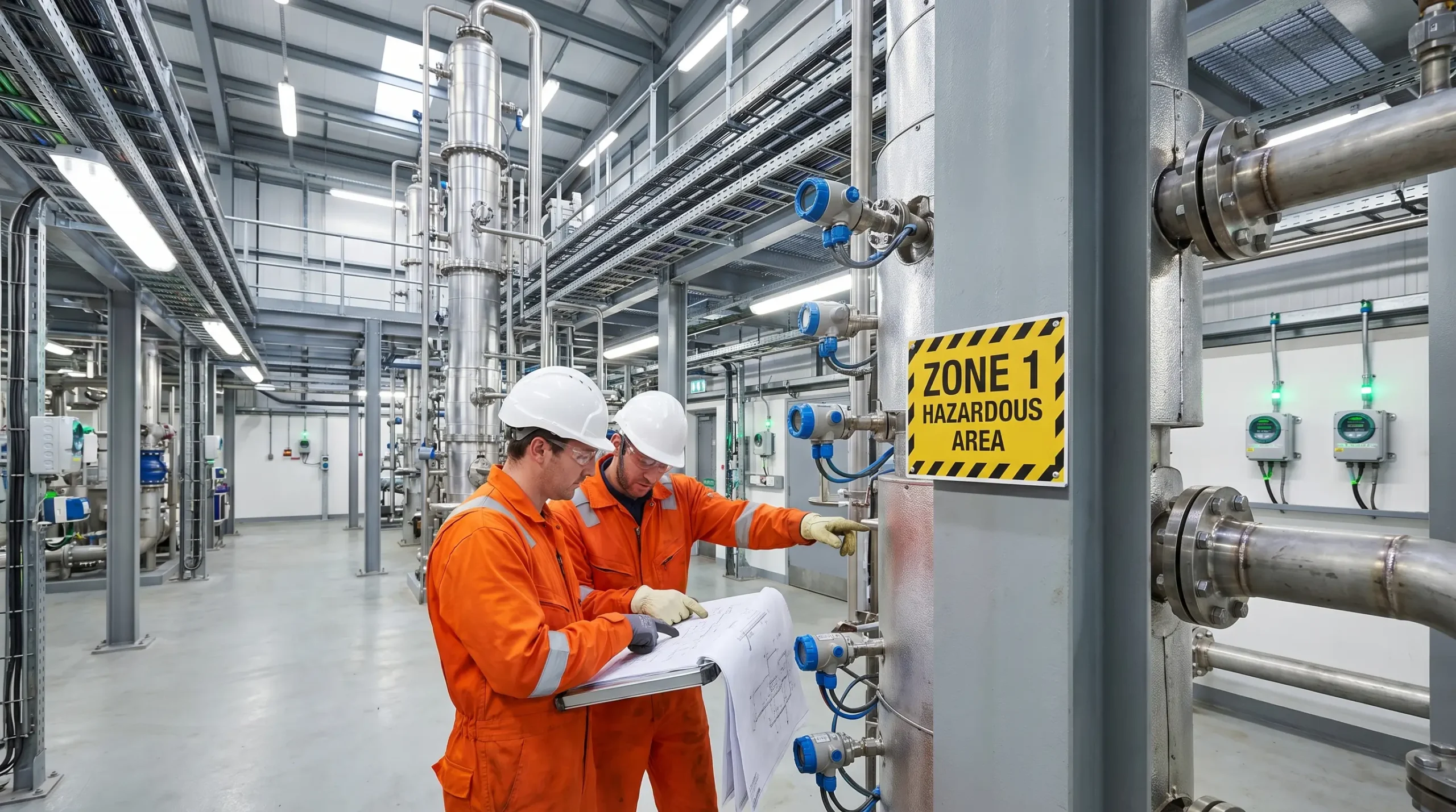
The vapor space inside a solvent recovery vessel is invisible. You cannot see the cyclohexane concentration climbing past its lower explosive limit. You cannot hear the gas-air ratio reaching stoichiometric balance. What you can see is the classification label bolted to the access hatch — Zone 0 — and the intrinsically safe transmitter wired into the level instrument, its circuit energy mathematically incapable of producing a spark with enough thermal energy to ignite what’s inside. That label and that transmitter are the end products of a classification decision made by an engineer months or years before any solvent entered the vessel. Every piece of electrical and non-electrical equipment within and around that vessel traces its specification back to a single determination: which zone?
The zone classification system exists because explosive atmospheres are not hypothetical in process industries — they are operational certainties. The question is never whether flammable gas or vapor will be present, but where, how often, and for how long. These three variables determine whether a location is classified as Zone 0, Zone 1, or Zone 2, and each zone carries fundamentally different requirements for equipment selection, installation practices, maintenance procedures, and human access. Misunderstanding the distinctions — or worse, misapplying them — is one of the most consequential engineering errors in explosion protection. This article breaks down every technical difference between the three zones, explains how zones are determined, maps the equipment requirements for each, and addresses the classification mistakes that persist across industries despite decades of regulatory guidance.
What Is Hazardous Area Classification?
Hazardous area classification is a systematic engineering method for identifying and categorizing locations where explosive atmospheres may form, so that every ignition source within those locations can be controlled. The purpose is not to prevent flammable substances from being present — in most chemical, pharmaceutical, and petrochemical operations, their presence is the entire point of the process. The purpose is to ensure that wherever a flammable gas, vapor, mist, or dust could mix with air in concentrations within the explosive range, no equipment or activity capable of providing an ignition source is permitted unless it has been specifically designed and certified to operate safely in that environment.
The foundational principle is the fire triangle: fuel, oxygen, and an ignition source must coexist for a fire or explosion to occur. In process facilities, fuel — the flammable substance — is a process material. Oxygen is ambient air. The only leg of the triangle that can be reliably eliminated through equipment specification is the ignition source. Hazardous area classification serves this objective by defining zones that represent the probability and duration of an explosive atmosphere being present, then dictating the level of ignition protection equipment must provide in each zone.
A critical distinction most practitioners internalize early in their careers: zones define likelihood, not severity. A Zone 2 explosion is not smaller or less violent than a Zone 0 explosion. If ignition occurs in any zone, the consequences can be equally catastrophic. The zone number tells you how often the explosive atmosphere is expected to be there — and therefore how rigorous the ignition protection must be. This classification framework applies across oil and gas production, chemical manufacturing, pharmaceutical processing, grain handling, paint and coating operations, mining, and any facility where flammable or combustible materials are stored, processed, or transferred.
How Zones Are Determined: Grade of Release and Ventilation
This is where most explanations of zone classification stop short. Competitors define the zones, list examples, and move on. But zone assignment is not a matter of professional opinion or conservative guessing — it follows a structured methodology prescribed by IEC 60079-10-1:2020, and the two inputs to that methodology are the grade of release and the ventilation conditions.
Grade of Release
The grade of release describes the expected frequency and duration of a flammable substance escaping from its containment. IEC 60079-10-1 defines three grades.
A continuous grade of release occurs when flammable material is released continuously or is expected to be present for long periods. The vapor space above an open-top solvent tank is a continuous release. So is the headspace inside a fixed-roof atmospheric storage tank containing a volatile liquid. A colleague once described it plainly during a classification workshop: “If you sealed the room and came back tomorrow, would the gas still be there? That’s continuous.”
A primary grade of release occurs periodically or occasionally during normal operation. Pump seals that weep during startup, sample points that vent briefly during routine sampling, pressure relief devices that lift during normal process upsets — these are primary releases. They happen as expected parts of the process cycle.
A secondary grade of release is not expected during normal operation and, if it occurs, will do so infrequently and for short periods. A flanged connection that only leaks if a gasket fails is a secondary release. So is a pipe fitting that would only release gas during an equipment malfunction.
Ventilation Assessment
Ventilation determines whether the released gas is diluted below its lower explosive limit — and how quickly. IEC 60079-10-1 assesses ventilation across two dimensions: availability (good, fair, or poor — reflecting how reliably ventilation operates) and effectiveness (high, medium, or low — reflecting how well it dilutes the release to below explosive concentrations).
When these two factors combine, the zone emerges. A continuous-grade release in a poorly ventilated enclosure produces Zone 0. A primary-grade release in a well-ventilated open area typically produces Zone 1 — or even Zone 2 if dilution is rapid and reliable. A secondary-grade release in an open, well-ventilated outdoor environment may result in Zone 2 of negligible extent, or may not require classification at all if dilution is sufficient to prevent any explosive concentration from forming.
IEC 60079-10-1 Table D.1 maps these combinations. I have yet to walk through a classification study where that table didn’t settle at least one disagreement among the assessment team.
| Grade of Release | Ventilation Effectiveness | Typical Zone Assignment |
|---|---|---|
| Continuous | Low / Poor availability | Zone 0 |
| Continuous | Medium / Good availability | Zone 1 (Zone 0 near source) |
| Continuous | High / Good availability | Zone 2 (Zone 1 near source) |
| Primary | Low / Poor availability | Zone 1 |
| Primary | Medium / Good availability | Zone 1 or Zone 2 |
| Primary | High / Good availability | Zone 2 or non-hazardous |
| Secondary | Low / Poor availability | Zone 1 or Zone 2 |
| Secondary | Medium / Good availability | Zone 2 |
| Secondary | High / Good availability | Zone 2 or non-hazardous |
The concept of “negligible extent” also sits within this framework. Where ventilation dilutes a release so rapidly that the explosive cloud never exceeds a volume small enough to cause harm, the area may be declassified entirely. This determination requires quantitative analysis, not assumption.
Zone 0: Continuous or Prolonged Explosive Atmosphere
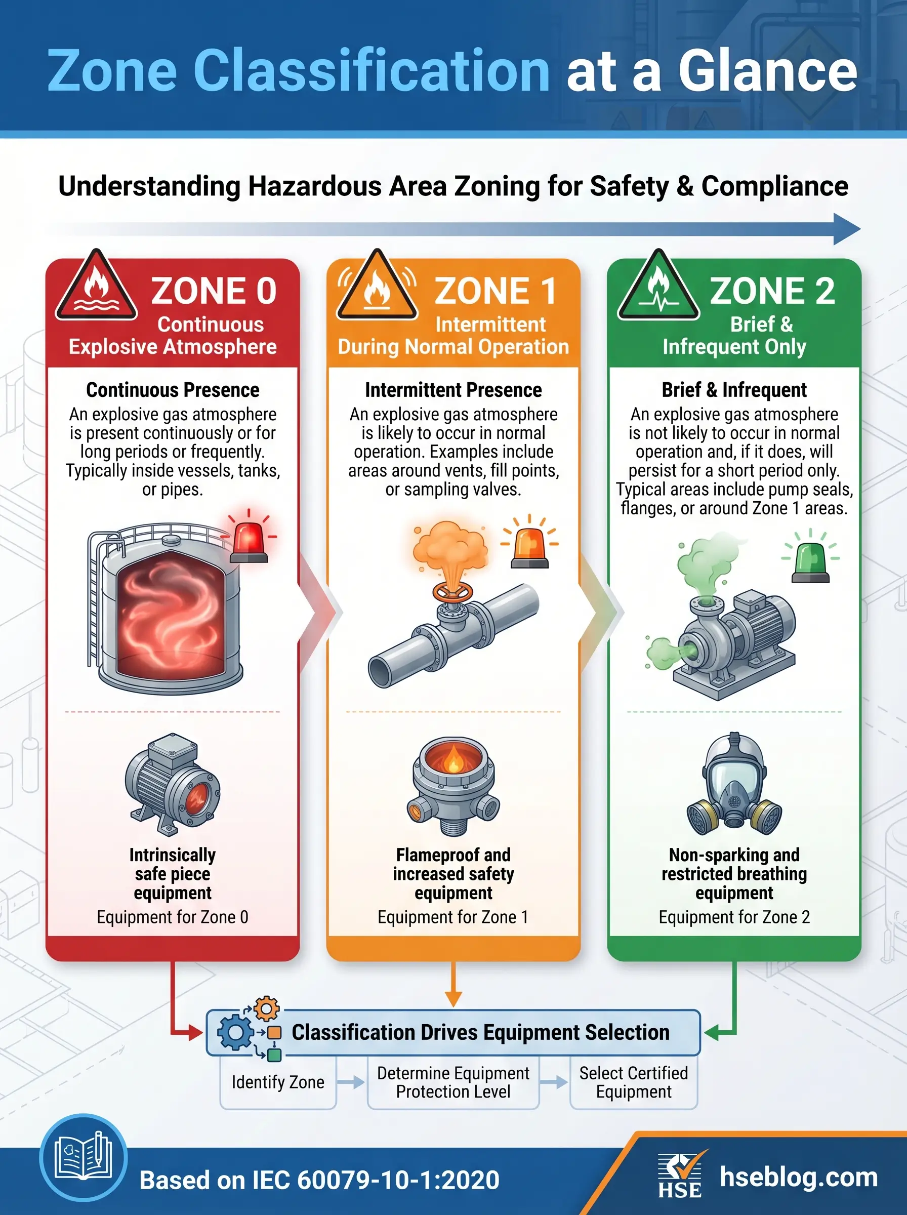
Zone 0 is the highest-risk classification in the zone system. It designates a location where an explosive gas atmosphere is present continuously, for long periods, or frequently. The UK HSE’s technical guidance sometimes applies an approximate quantitative threshold: a Zone 0 area is one where an explosive atmosphere exists for more than 1,000 hours per year.
In practice, Zone 0 areas are almost never occupied workspaces. They are the interiors of process vessels containing flammable liquids with headspaces at or above the lower explosive limit. They are the vapor spaces inside fixed-roof storage tanks holding volatile solvents. They are the interiors of pipelines transporting flammable gas. During a vessel entry classification review on a specialty chemical plant’s distillation column, the discussion was brief — the column internals are Zone 0 during operation, Zone 1 during gas-freeing procedures before entry, and unclassified only after gas testing confirms concentrations below the detection threshold. There was nothing to debate.
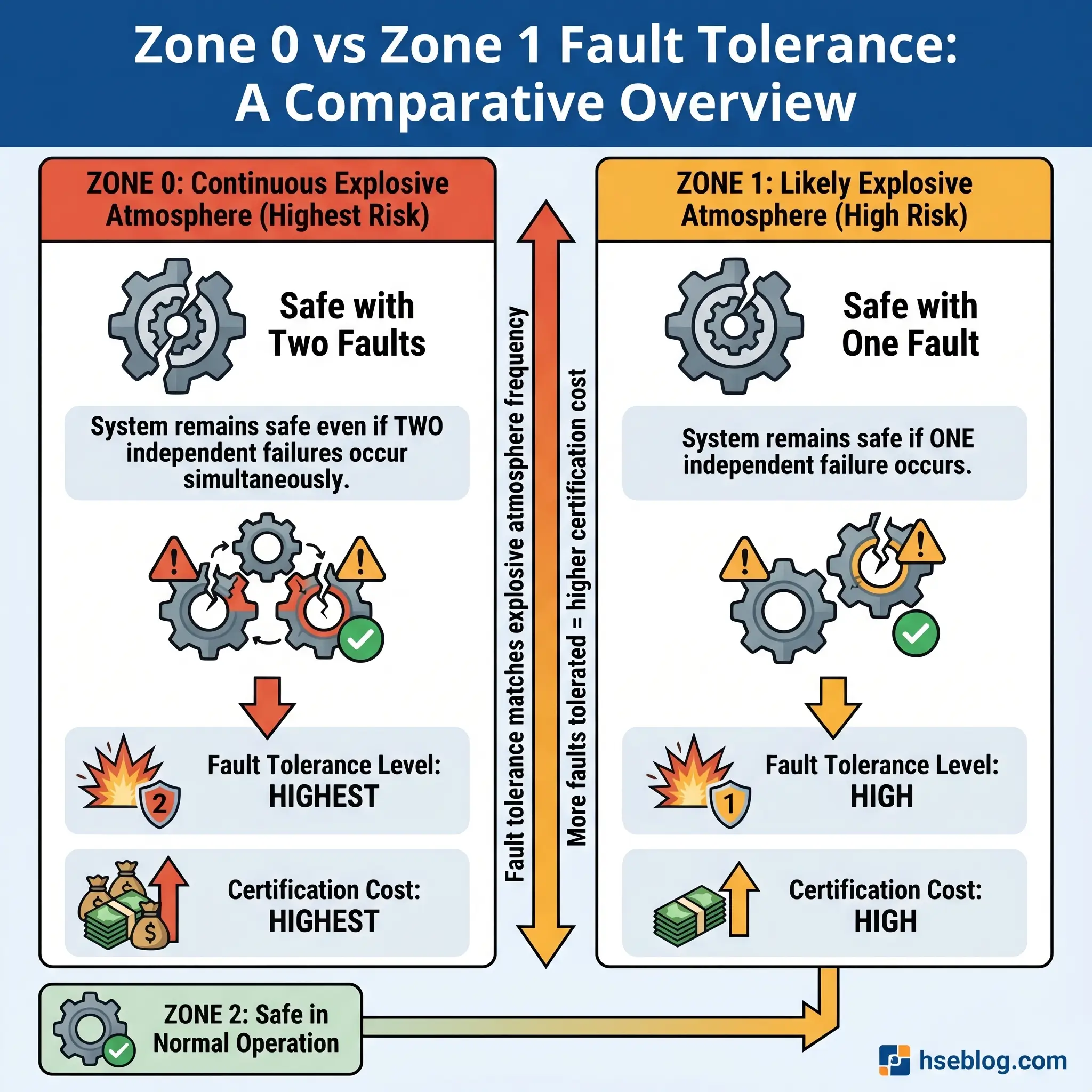
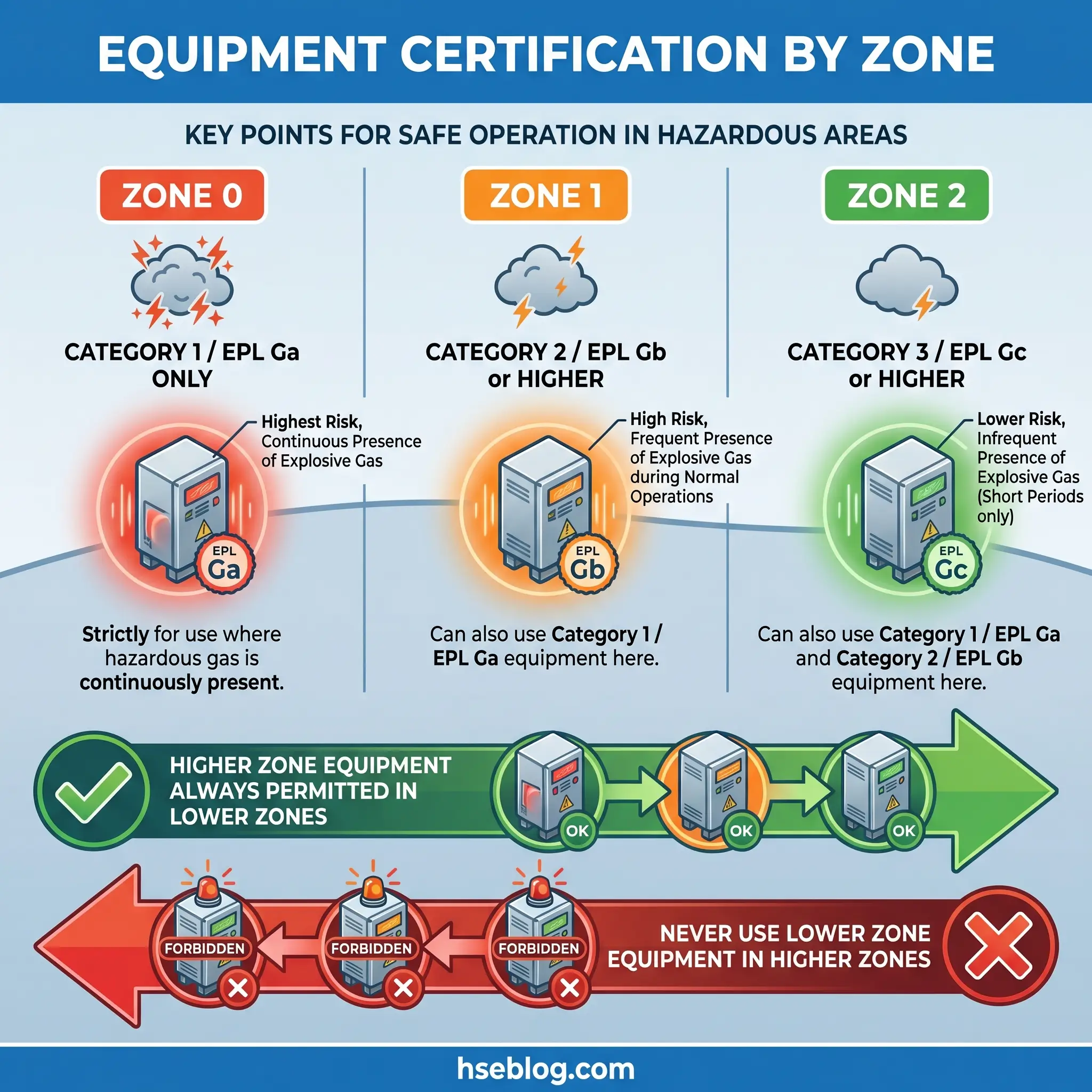
Equipment permitted in Zone 0 must meet the most demanding certification standard: ATEX Category 1 equipment, or IECEx Equipment Protection Level Ga. The dominant protection concept is intrinsic safety at its highest level — Ex ia — where the circuit design ensures that even with two simultaneous faults, the energy available in the circuit remains below the minimum ignition energy of the target gas. Zone 0 also permits encapsulated equipment rated Ex ma, where the potential ignition source is physically sealed within a compound that prevents contact with the explosive atmosphere.
The two-fault tolerance requirement is what separates Zone 0 from everything else. A Zone 0 device must remain incapable of ignition even when two independent safety barriers fail simultaneously.
Zone 1: Explosive Atmosphere Likely During Normal Operation
Zone 1 is the classification that occupies the most real estate on a typical hazardous area drawing — and the zone where the majority of industrial work activity in explosive atmospheres takes place. It designates a location where an explosive gas atmosphere is likely to occur occasionally during normal operations. The approximate time threshold: between 10 and 1,000 hours per year.
Zone 1 typically surrounds Zone 0 areas. It forms around pump seal faces, valve packing glands, flanged pipe connections, sample points, open drainage systems, and filling stations where liquid transfer creates localized vapor clouds. On the chemical processing facility I work in, the drum filling station is a textbook Zone 1 area — every fill cycle generates a brief solvent vapor release as the liquid stream breaks surface tension inside the drum. It happens during normal production. It is expected.
The familiar example most classification guides cite is a petrol station forecourt, where vehicle refueling creates intermittent gasoline vapor releases at the nozzle during every fill. That Zone 1 area is surrounded by Zone 2, which extends further from the dispenser into the open forecourt.
Equipment in Zone 1 must be certified to ATEX Category 2 or IECEx Equipment Protection Level Gb. The range of permitted protection concepts is broader than Zone 0: flameproof enclosures (Ex d), which contain an internal explosion and cool the gases before they escape; increased safety (Ex e), which eliminates arcs and hot surfaces through enhanced construction; pressurization (Ex p), which maintains a positive internal pressure of clean air or inert gas to prevent explosive atmosphere entry; intrinsically safe circuits at the Ex ib level; and encapsulation (Ex mb).
The distinction from Zone 0: Zone 1 equipment must remain safe with one fault condition. This is the one-fault tolerance requirement — one safety barrier may fail, and the equipment must still not become an ignition source.
Zone 2: Explosive Atmosphere Unlikely Under Normal Conditions
Zone 2 designates the lowest-risk hazardous classification — but it is still a classified hazardous area. Equipment that is safe for general-purpose use in a standard industrial setting is not safe for Zone 2. This is the mistake that experienced electrical engineers have described seeing repeated on commissioning punch lists more often than any other: standard junction boxes, lighting fixtures, or cable glands installed in Zone 2 because someone assumed “unlikely” meant “won’t happen.”
The IEC definition: a location where an explosive gas atmosphere is not expected to occur during normal operation, and if it does occur, it will persist only for a short period. The approximate threshold is fewer than 10 hours per year — but those hours are sufficient to require certified equipment.
Zone 2 areas typically form at the outer boundaries of Zone 1 regions in open, well-ventilated environments. They include the vicinity of flanged connections in outdoor pipe racks, areas surrounding Zone 1 boundaries on open-air pump skids, spaces near sealed containers in well-ventilated storage buildings, and the discharge areas around pressure relief valves where a brief release is possible only during abnormal overpressure events.
Equipment in Zone 2 must meet ATEX Category 3 or IECEx Equipment Protection Level Gc. The primary protection concept is type “n” protection — Ex nA (non-sparking), Ex nC (sparking contacts in sealed or encapsulated chambers), and Ex nR (restricted breathing enclosures). These are simpler and more cost-effective than Zone 1 methods, reflecting the lower probability of an explosive atmosphere being present.
A noteworthy regulatory detail: the ATEX Directive permits manufacturer self-certification for some Category 3 equipment. This contrasts with Category 1 and 2 equipment, which must be assessed by a notified body. The cost difference between Zone 0 and Zone 2 equipment can be substantial — in one facility retrofit project, the price differential between an Ex ia (Zone 0) and an Ex nA (Zone 2) junction box of similar size was nearly fourfold.
Watch For: The rare explosive atmosphere in Zone 2 has historically caused serious incidents precisely because complacency follows infrequency. A Zone 2 classification does not mean the atmosphere is safe — it means it is safe most of the time.
Zone 0 vs Zone 1 vs Zone 2: Side-by-Side Comparison
The search intent behind “Zone 0, Zone 1, Zone 2 differences explained” is answered most directly in a structured comparison. Every differentiating factor is summarized here for quick reference.
| Differentiating Factor | Zone 0 | Zone 1 | Zone 2 |
|---|---|---|---|
| Explosive atmosphere frequency | Continuous, prolonged, or frequent | Occasional during normal operation | Unlikely during normal operation; brief if it occurs |
| Approximate time threshold | >1,000 hours/year | 10–1,000 hours/year | <10 hours/year |
| Risk level | Highest | Intermediate | Lowest (still hazardous) |
| Typical locations | Inside vessels, tanks, pipelines | Around pump seals, valve glands, fill points | Outer perimeter of Zone 1, near sealed containers |
| ATEX equipment category | Category 1 | Category 2 | Category 3 |
| IECEx EPL | Ga | Gb | Gc |
| Primary protection methods | Ex ia, Ex ma | Ex d, Ex e, Ex p, Ex ib, Ex mb | Ex nA, Ex nC, Ex nR, Ex ic |
| Fault tolerance | Safe with 2 simultaneous faults | Safe with 1 fault | Safe in normal operation only |
| Certification body | Notified body required | Notified body required | Manufacturer self-certification permitted (some items) |
| Relative equipment cost | Highest | Moderate to high | Lowest among hazardous zones |
| Human access | Typically restricted during operation | Routine work conducted with controls | Standard operational access with certified equipment |
One principle governs equipment interchangeability across zones: equipment certified for a higher-risk zone may always be used in a lower-risk zone, but never the reverse. An Ex ia (Zone 0) transmitter is fully compliant in Zone 1 and Zone 2. An Ex nA (Zone 2) junction box placed in Zone 1 is a compliance violation and an ignition risk.
Dust Zones: Zone 20, Zone 21, and Zone 22
The zone classification system for combustible dusts mirrors the gas zone system in logic but is governed by a separate standard — IEC 60079-10-2:2015. Practitioners searching for Zone 0, 1, and 2 information frequently also need to understand their dust equivalents, particularly in facilities that handle powders, granules, or fibrous materials alongside flammable gases.
Zone 20 is the dust equivalent of Zone 0 — a location where a combustible dust cloud is present continuously, for long periods, or frequently. The interior of a grain silo during filling, the inside of a dust collector during operation, and the containment space of a powder milling machine are typical Zone 20 environments.
Zone 21 parallels Zone 1 — occasional dust clouds during normal operation. Powder transfer stations, bag-tipping areas, and the immediate vicinity of conveyor discharge points fall here. Zone 22 corresponds to Zone 2 — dust clouds are not expected during normal operation and persist only briefly if they do form. Areas near sealed duct connections, the periphery of well-maintained extraction systems, and spaces adjacent to Zone 21 boundaries are common Zone 22 locations.
| Dust Zone | Gas Equivalent | ATEX Category | Typical Locations |
|---|---|---|---|
| Zone 20 | Zone 0 | 1D | Inside silos, dust collectors, mills |
| Zone 21 | Zone 1 | 2D | Powder transfer, bag dumping stations |
| Zone 22 | Zone 2 | 3D | Near ducts, sealed handling areas |
Hybrid environments — where both flammable gas and combustible dust coexist — require engineering assessment beyond standard zone tables. IEC 60079-10-1 and 60079-10-2 do not provide a combined methodology for hybrid mixtures. In pharmaceutical granulation areas where solvent vapors and active ingredient dust are simultaneously present, the classification study must address both hazards independently and apply the more restrictive outcome at each location.
How Zones Relate to the North American Class/Division System
The IEC zone system and the NEC Class/Division system serve the same purpose — controlling ignition sources in areas where explosive atmospheres may occur — but they carve the probability spectrum differently. This cross-reference is consistently missing from competitor articles, yet it matters for any organization operating across jurisdictions or sourcing equipment internationally.
The NEC Class/Division system, used throughout the United States and Canada, divides hazardous locations into two levels of probability. Class I, Division 1 encompasses locations where explosive gas atmospheres are expected during normal operation or during frequent maintenance activities. Class I, Division 2 covers locations where explosive atmospheres occur only during abnormal conditions — equipment failure, accidental rupture, or unusual operation.
The zone system provides finer granularity by splitting Division 1 into two levels:
- Zone 0 + Zone 1 combined roughly corresponds to Class I, Division 1
- Zone 2 roughly corresponds to Class I, Division 2
The practical advantage of the zone system is that it distinguishes between continuous explosive atmospheres (Zone 0) and intermittent ones (Zone 1). In the Division system, both conditions receive the same classification — and therefore the same equipment requirements. This means a Division 1 location pays for Division 1 equipment everywhere, even in areas where the continuous Zone 0 level of protection was never necessary.
OSHA 29 CFR 1910.307 permits the zone system as an alternative to the division system for Class I locations in the United States, and NEC Article 505 provides the corresponding installation requirements for zone-classified locations. However, equipment certified under one system cannot be automatically used under the other without cross-certification or mutual recognition — a point that procurement teams encounter regularly when sourcing equipment from international manufacturers.
| Zone System | Division System | Probability Level |
|---|---|---|
| Zone 0 | Class I, Division 1 (partial) | Continuous or prolonged |
| Zone 1 | Class I, Division 1 (partial) | Intermittent, normal operation |
| Zone 2 | Class I, Division 2 | Abnormal conditions only |
Equipment Selection and Protection Methods by Zone
Moving from classification theory to practical application — the zone determines not only the equipment protection level required but the specific protection concepts permitted. Each concept addresses ignition prevention through a different engineering principle.
Intrinsic safety (Ex i) limits circuit energy — voltage, current, and stored energy — below the minimum ignition energy of the target gas. Ex ia is the highest level, providing two-fault safety for Zone 0. Ex ib provides one-fault safety for Zone 1. Ex ic is permitted in Zone 2 only.
Flameproof enclosures (Ex d) accept that an internal explosion may occur but contain it within a robust enclosure. Flame paths machined to precise tolerances cool escaping gases below their ignition temperature. This concept applies primarily in Zone 1.
Increased safety (Ex e) eliminates sparks, arcs, and excessive surface temperatures through enhanced construction standards — wider creepage distances, higher-quality terminals, temperature-monitored windings. Permitted in Zone 1 and Zone 2.
Pressurization (Ex p) maintains positive internal pressure with clean air or inert gas, preventing explosive atmosphere from entering the enclosure. Used in Zone 1 and Zone 2, often for large motors or analytical equipment that cannot be made intrinsically safe.
Type “n” protection (Ex n) is exclusive to Zone 2. It provides basic non-sparking construction (Ex nA), sealed or encapsulated contacts (Ex nC), or restricted breathing enclosures (Ex nR). These methods cost less because they need only prevent ignition during normal operation — no fault tolerance is required.
Encapsulation (Ex m) seals potential ignition sources in a compound that prevents gas contact. Ex ma is permitted in Zone 0, Ex mb in Zone 1.
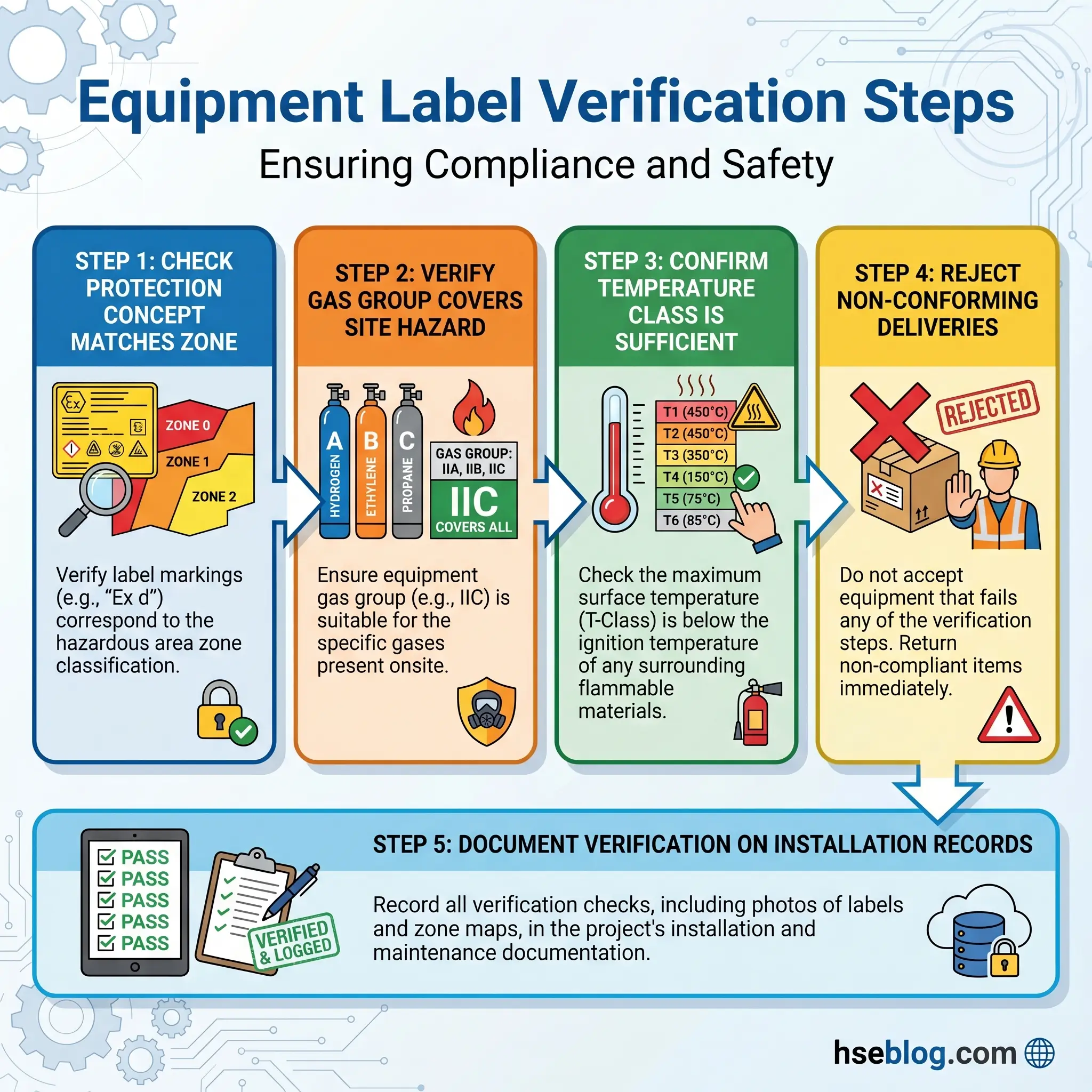
Beyond the protection concept, two additional parameters must match the specific hazard: the gas group and the temperature class. Gas groups — IIA (propane and similar), IIB (ethylene and similar), IIC (hydrogen and acetylene) — reflect the minimum ignition energy and maximum experimental safe gap of the target substance. Temperature classes — T1 through T6 — define the maximum permissible surface temperature of the equipment relative to the gas’s auto-ignition temperature.
Field Test: Before accepting any equipment delivery for a hazardous area, check three things on the certification label: protection concept (matches the zone), gas group (matches or exceeds the site’s classified gas), and temperature class (matches or exceeds the site’s classified temperature requirement). If any one of the three is wrong, reject the delivery. I watched a commissioning team install IIB-rated junction boxes in an area classified for hydrogen — a IIC gas. The boxes looked identical. The labels did not.
How to Conduct a Hazardous Area Classification Study
The classification study is the engineering process that produces the zone drawings and data sheets a facility operates under. It is not a desktop exercise completed by a single person — it requires a multidisciplinary team including process engineers, electrical engineers, and HSE professionals with competence in flammable substance properties, ventilation assessment, and the relevant IEC, ATEX, or NEC standards.
The following steps reflect the methodology prescribed by IEC 60079-10-1:2020.
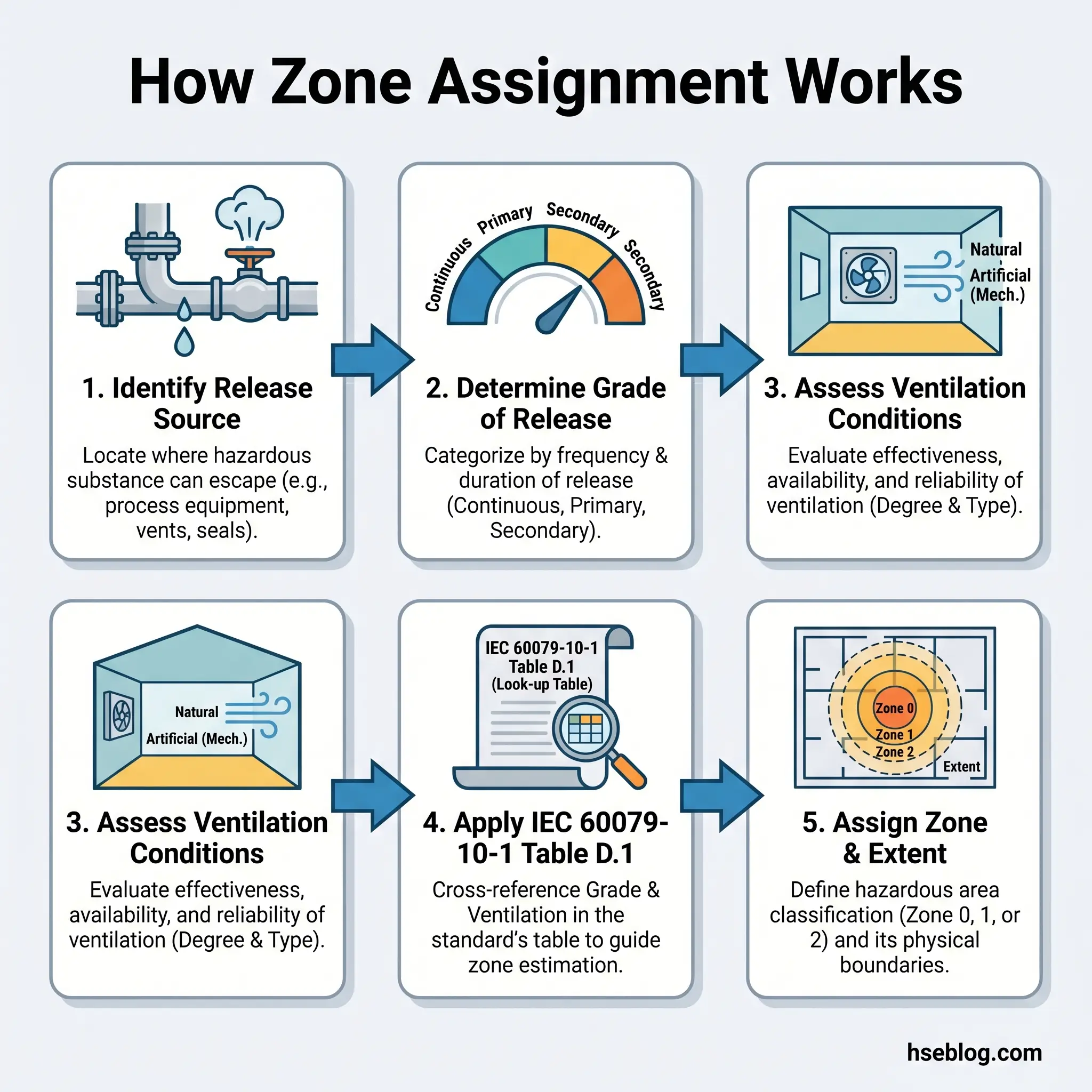
- Identify all sources of flammable release. Walk the facility — every vessel, pipe connection, valve, pump, compressor, storage container, loading point, and drainage path that contains, processes, or transfers a flammable substance is a potential release source. A comprehensive source register is the foundation.
- Determine the grade of release for each source. Classify each identified source as continuous, primary, or secondary. This determination is based on the source’s operating pattern — does it release during normal operation, only periodically, or only during abnormal conditions?
- Assess ventilation conditions. Evaluate the availability and effectiveness of ventilation at each release location. Outdoor, open-air locations with consistent wind flow will have different ventilation characteristics than enclosed pump rooms with mechanical extraction.
- Assign zone classification. Apply IEC 60079-10-1 methodology — including Table D.1 — to determine the zone for each area based on the grade of release and ventilation combination.
- Determine the extent of each zone. Define the physical boundaries — how far does each zone extend from the release source? IEC 60079-10-1 provides methods for calculating zone extent based on release rate, ventilation velocity, and gas properties. The extent defines the volume of space that requires classified equipment.
- Document findings. Record the classification on hazardous area drawings and data sheets. These documents are living records — they form the basis for equipment specification, installation verification, and regulatory compliance audits.
Under the UK’s Dangerous Substances and Explosive Atmospheres Regulations (DSEAR 2002), classification must be reviewed at least every five years, or sooner if there is any change to process materials, operating conditions, plant layout, or ventilation systems.
Audit Point: “Blanket classification” — classifying an entire facility or large area as Zone 1 to avoid the effort of detailed assessment — is a practice auditors recognize immediately. It inflates capital expenditure on over-specified equipment, and it implicitly accepts that explosive atmospheres can form everywhere. Accurate classification is both safer and more cost-effective.
Common Mistakes in Zone Classification
Classification errors persist across industries because the process sits at the intersection of process engineering, electrical engineering, and safety management — and miscommunication between these disciplines is common. The following mistakes appear repeatedly in classification audits and incident investigations.
- Over-classification (blanket Zone 1) treats entire operating areas as Zone 1 regardless of actual release probability. Capital costs rise dramatically. On one facility expansion project, a reclassification study downgraded 40% of the blanket Zone 1 area to Zone 2, reducing the equipment budget for that area by an estimated 30%.
- Under-classification (marking Zone 1 as Zone 2) creates serious safety and compliance risk. If intermittent releases during normal operation occur in an area classified as Zone 2, the installed Ex n equipment lacks the fault tolerance to prevent ignition during a coincident release and equipment fault.
- Failing to account for ventilation changes after plant modifications. A wall added to shelter a pump skid, a louvre sealed to reduce noise, a mechanical ventilation fan decommissioned during cost reduction — each changes the ventilation assessment and may shift the zone classification. If the zone drawings are not updated, the installed equipment may no longer be appropriate.
- Installing equipment rated for the wrong gas group. Gas group IIB equipment installed in a hydrogen (IIC) environment is a certification mismatch that existing visual inspections can miss if the inspector is checking only the protection concept and not the full label. Hydrogen’s minimum ignition energy is approximately one-tenth that of propane.
- Neglecting non-electrical ignition sources. Zone classification often focuses exclusively on electrical equipment, but hot surfaces, static discharge, mechanical friction, and adiabatic compression are all capable ignition sources. ATEX Directive 1999/92/EC (ATEX 153) specifically requires employers to consider all ignition sources — not only electrical ones.
- Not updating zone drawings after process changes. A new product, a new solvent, a rerouted pipeline, or a changed operating temperature can alter both the grade of release and the properties of the released substance. Zone drawings that do not reflect the current process state are compliance liabilities.
Why Correct Zone Classification Matters: Safety and Cost Implications
Accurate zone classification sits at the intersection of two organizational priorities that are often framed as competing: safety performance and capital efficiency. In reality, they are aligned. Over-classification wastes resources. Under-classification risks lives.
On the safety side, correct classification ensures that ignition sources are controlled in proportion to the probability of an explosive atmosphere being present. Zone 0 areas receive the most rigorous protection because they need it continuously. Zone 2 areas receive lighter — but still certified — protection because the explosive atmosphere is a rare event. This proportionality is not a cost-saving shortcut; it is the engineering logic that makes explosion protection sustainable and focused.
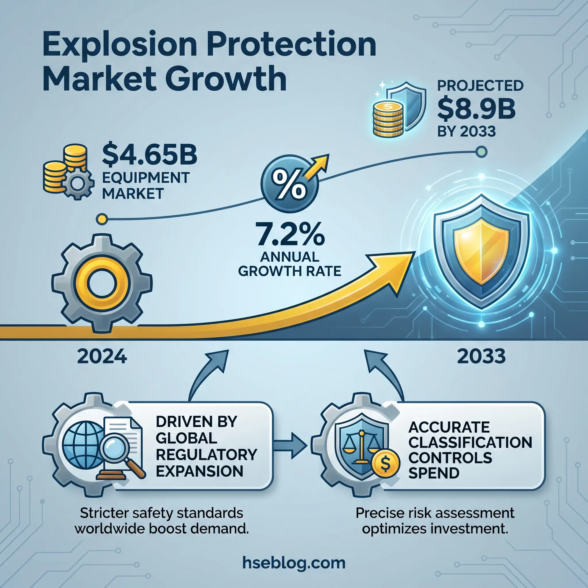
On the cost side, the financial implications are significant. The global explosion-proof equipment market generated approximately $4.65 billion in 2024 — a figure that reflects how much industry invests in certified hardware. The industrial explosion protection solution market is projected to reach $8.9 billion by 2033, growing at a 7.2% CAGR, driven by intensifying global regulatory enforcement and the expansion of ATEX and IECEx frameworks into emerging industrial markets. When a facility over-classifies, it absorbs unnecessary shares of that cost. When it classifies accurately, every dollar spent on certified equipment is a dollar spent where the risk actually exists.
From a compliance perspective, regulatory enforcement is explicit. DSEAR in the UK, OSHA 29 CFR 1910.307 in the United States, and the ATEX workplace directive (1999/92/EC) across the European Union all require documented hazardous area classification. Failure to classify — or failure to maintain current classifications — is an enforceable violation. Insurance implications parallel the regulatory ones: proper classification and documented compliance can positively influence premium assessments, while undocumented or inaccurate classifications undermine coverage positions.
The current edition of IEC 60079-10-1 — Edition 3.0, published in 2020 — replaced the 2015 Edition 2.0 with technical revisions to ventilation assessment methodology, zone extent calculations, and recognition of alternative classification approaches. As of 2025, no further major revisions have been issued, and NEC Article 505 now fully aligns with the IEC zone system for US installations. This stability confirms that the classification framework described throughout this article represents the current international standard of practice.
Frequently Asked Questions
Conclusion
The pattern the industry consistently gets wrong is not the definitions — most engineers can recite what Zone 0, Zone 1, and Zone 2 mean. The failure point is in the methodology: treating zone classification as a labeling exercise rather than an engineering analysis. When classification is done properly — release sources identified, grades assigned, ventilation assessed, extent calculated, and drawings maintained as living documents — the zone system delivers exactly what it was designed to deliver. Equipment spending targets genuine risk. Ignition sources are controlled where explosive atmospheres actually exist. Documentation withstands regulatory scrutiny.
The single highest-impact change any facility can make to its explosion protection program is to stop accepting inherited classifications and blanket zones as permanent fixtures. Challenge the zone drawings. Ask when the classification study was last reviewed. Verify that the process described on paper matches the process running in the plant today. IEC 60079-10-1:2020 provides the methodology. ATEX, OSHA, and DSEAR provide the legal obligation. What remains is the engineering discipline to apply them accurately — because the consequences of getting the zone wrong are measured in equipment failures at the mild end and body counts at the severe end.
Every zone on a hazardous area drawing represents a decision. Make certain it was the right one.