
Thirty-two people went to work in our industry in 2024 and did not come home. The IOGP Safety Performance Indicators 2024 Data report records those 32 fatalities across 21 separate incidents — more than the 27 recorded the year before. Set against the decade-long picture, where the fatal accident rate has dropped by roughly 36%, the 2024 number is both an improvement story and a warning. The fatal accident rate of around 0.89 per 100 million hours worked is the lowest the industry has ever posted. It is also still, by US Bureau of Labor Statistics data, more than six times the all-industry average for fatal injuries.
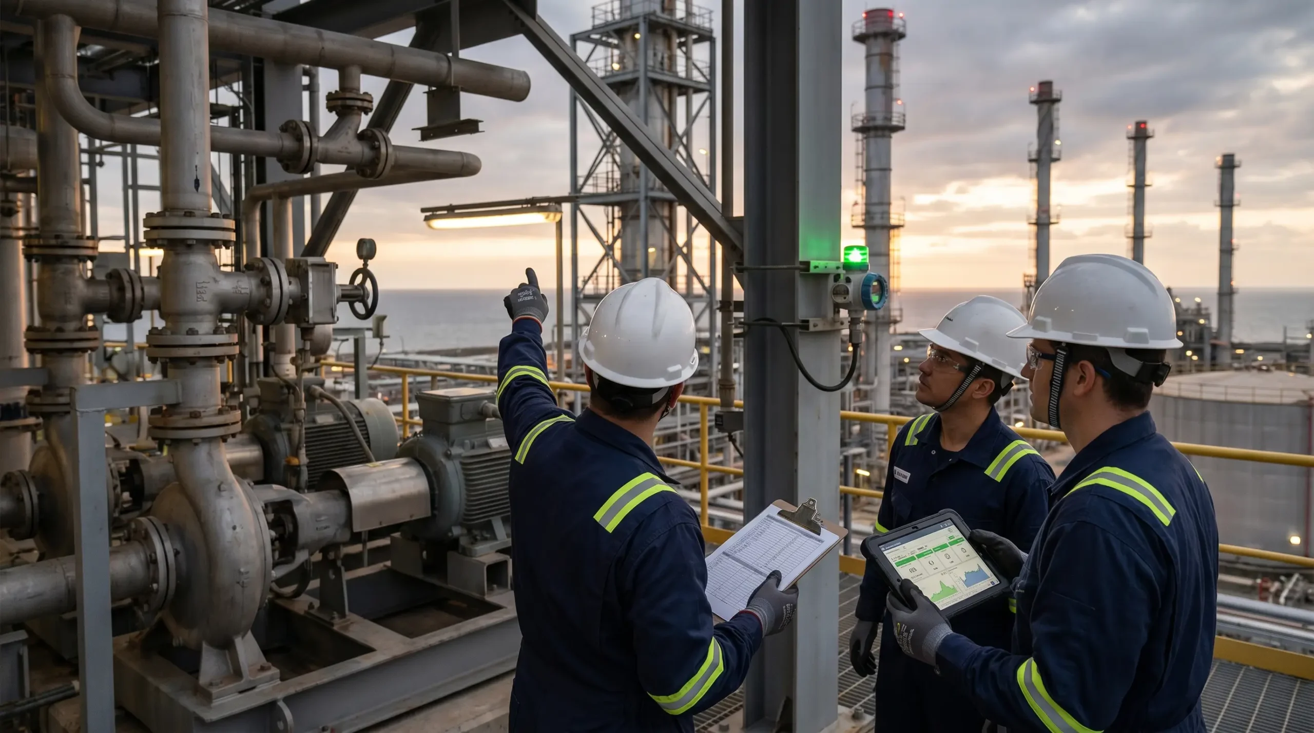
That tension — measurable progress alongside persistent catastrophic potential — is exactly why a disciplined look at the industry’s top hazards still matters. On our refinery’s east-side control room wall, there is a framed print of the IOGP causal factors list. Every new engineer looks at it on their first day. Not because the hazards are new, but because every major incident investigation — from Piper Alpha forward — has found the same handful of causes hiding behind different faces.
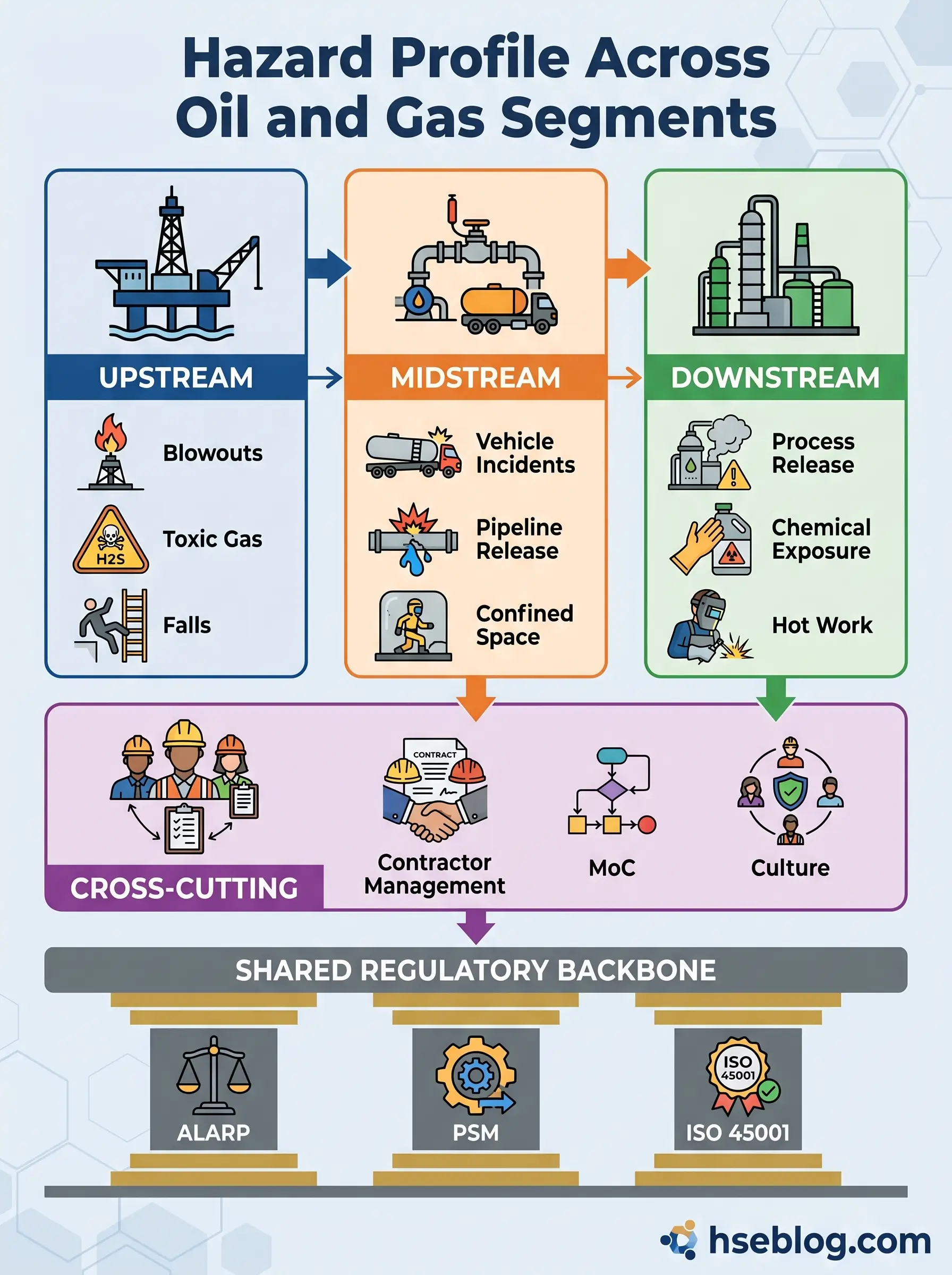
The industry operates across three broadly different worlds. Upstream covers exploration, drilling, and production — the rigs, platforms, and well pads where hydrocarbons are pulled out of the ground. Midstream moves the product through pipelines, rail, road, and tankers. Downstream is refining, petrochemical conversion, and distribution to end users. The hazards overlap heavily but the dominant risks shift. A drilling crew thinks about blowouts first; a refinery shift supervisor thinks about hydrocarbon release and runaway reactions; a pipeline operator thinks about third-party damage and dispersion modelling. This article applies one consistent framework — the hierarchy of controls — across all three segments.
The Framework: How Oil and Gas Operators Actually Control Hazards
Before working through the ten hazards themselves, it’s worth being explicit about the control logic that the rest of the article applies. Most top-10 listicles skip this step and the result is a catalogue of problems with no organising principle behind the solutions.
The hierarchy of controls sits at the heart of every credible oil and gas safety management system. Five layers, in descending order of effectiveness:
- Elimination — remove the hazard entirely. Designing a facility so that hot work is not required for a tank inspection is elimination.
- Substitution — replace the hazardous material or process with something less dangerous. Using a non-flammable solvent in place of a flammable one.
- Engineering controls — physical barriers, ventilation, interlocks, relief systems, hazardous area classification. The hardware that protects people without asking them to remember anything.
- Administrative controls — procedures, permits, training, supervision. Works only when people follow them, and under pressure people sometimes don’t.
- Personal protective equipment — the last line, not the first.
The common mistake across the industry is treating PPE and procedures as if they were on equal footing with engineered barriers. They are not. A properly designed relief valve does not forget. A fire-and-gas detection system does not skip a step because the job is running late.
Running parallel to the hierarchy is the ALARP principle — reducing risk to a level that is As Low As Reasonably Practicable. ALARP, central to the UK’s Offshore Installations (Safety Case) Regulations 2015 and adopted by most internationally regulated operators, asks a harder question than “have we complied?”. It asks whether the residual risk is grossly disproportionate to the cost of further reduction. Duty holders must demonstrate, not assert, that it is.
A third distinction every oil and gas practitioner has to carry is between occupational safety hazards — slips, trips, manual handling, hand injuries — and process safety hazards, which are major accident hazards with the potential for multiple fatalities, asset destruction, and community impact. Both categories are measured, managed, and reported separately. API RP 754 defines Tier 1 through Tier 4 process safety events precisely so that operators cannot mask a loss-of-containment record by pointing to a strong TRIR.
Underneath all of this sits the safety case or its equivalent management system — a structured demonstration, approved by a competent regulator, that major accident hazards have been identified, that barriers are in place, and that those barriers are being maintained. It is what separates an operator who understands their hazards from one who simply lists them.
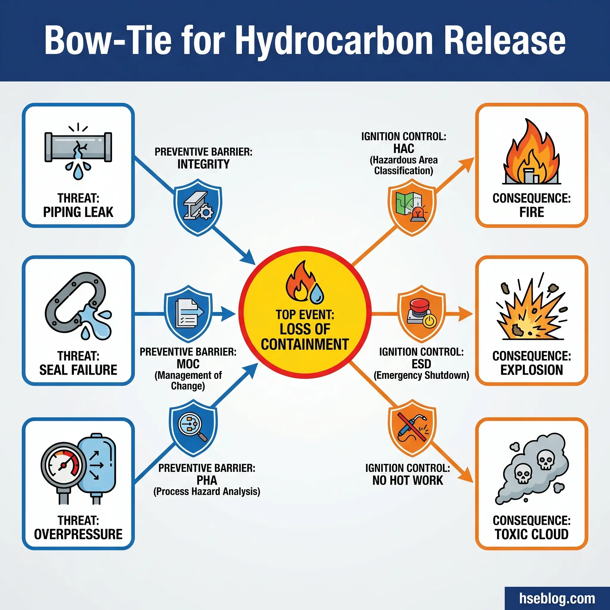
Finally, the mental model that appears in every hazard section below: bow-tie analysis. On the left, threats. In the centre, the top event (usually loss of containment or loss of control). On the right, the consequences. Between threats and top event sit preventive barriers; between top event and consequences sit mitigative barriers. If you can draw the bow-tie for a hazard, you can manage it. If you cannot, you are guessing.
Hazard 1: Fire and Explosion from Hydrocarbon Release
Every fatality inquiry into Buncefield (2005), Texas City (2005), and Jaipur (2009) reaches the same reading of the bow-tie: a release that should have been contained, an ignition source that should not have been live, and barriers that had quietly degraded long before the event. Fire and explosion from hydrocarbon release is the defining hazard of the industry because it owns the catastrophic tail of the risk distribution.
The release side of the bow-tie is dominated by a small number of mechanisms. Piping and flange leaks during maintenance or restart are the single most common initiating event across downstream incident databases. Mechanical seal failure on rotating equipment — centrifugal pumps in particular — runs a close second. Overpressure events from relief system undersizing or isolation errors account for the most consequential single releases. Atmospheric tanks develop flammable vapour spaces under unplanned operating conditions. Between May 1992 and June 2007, the US petroleum refining industry alone logged 36 fatal or catastrophic incidents involving hazardous chemical releases, resulting in 52 deaths and 250 injuries.
The ignition side, as enumerated by OSHA’s Oil and Gas Extraction Hazards guidance, is depressingly unimaginative: static electricity, electrical equipment, open flames, lightning strikes, hot surfaces, frictional heat, welding and cutting. On a congested process unit, eliminating every ignition source is impossible. The strategy is to engineer the area so that the ignition sources that remain cannot reach a flammable atmosphere.
Hazardous area classification explained for non-specialists
Hazardous area classification is the discipline that makes this separation engineered rather than lucky. Under IEC 60079, plant areas are zoned by the probability of a flammable atmosphere being present:
- Zone 0 — flammable atmosphere present continuously or for long periods (inside a fuel tank vapour space, for example)
- Zone 1 — flammable atmosphere likely to occur in normal operation
- Zone 2 — flammable atmosphere unlikely in normal operation, and if present, only briefly
The older North American Class/Division system maps broadly onto the same logic. Any electrical equipment — motors, switchgear, instruments, junction boxes, torches — installed in a classified area must carry certification for that zone. Ex d (flameproof), Ex e (increased safety), Ex i (intrinsically safe) and the other protection concepts each solve the ignition problem differently, but the rule is absolute: uncertified equipment in a classified area is a prosecutable offence under DSEAR in the UK and an immediate write-up in any functioning safety management system.
The control architecture for fire and explosion therefore runs across the full hierarchy. Engineering controls include fixed gas and flame detection tied to executive action, hazardous area classification and certified equipment, emergency shutdown (ESD) systems, inerting and purging of vapour spaces, bunding and secondary containment, passive fire protection, deluge and foam systems, and overpressure relief sized per API 520/521. Administrative controls begin with the process safety management standard itself — OSHA 29 CFR 1910.119 in the United States and equivalent regimes under SCR 2015 and COMAH elsewhere. Hot work permits under 1910.119(k), management of change, mechanical integrity programmes, and process hazard analyses using HAZOP and LOPA are not optional extras. They are the administrative layer that keeps the engineered barriers honest. PPE — flame-resistant coveralls certified to NFPA 2112 or equivalent, and task-appropriate respiratory protection — is the last thing standing between a worker and a flash fire, and it must never be the first thing relied upon.
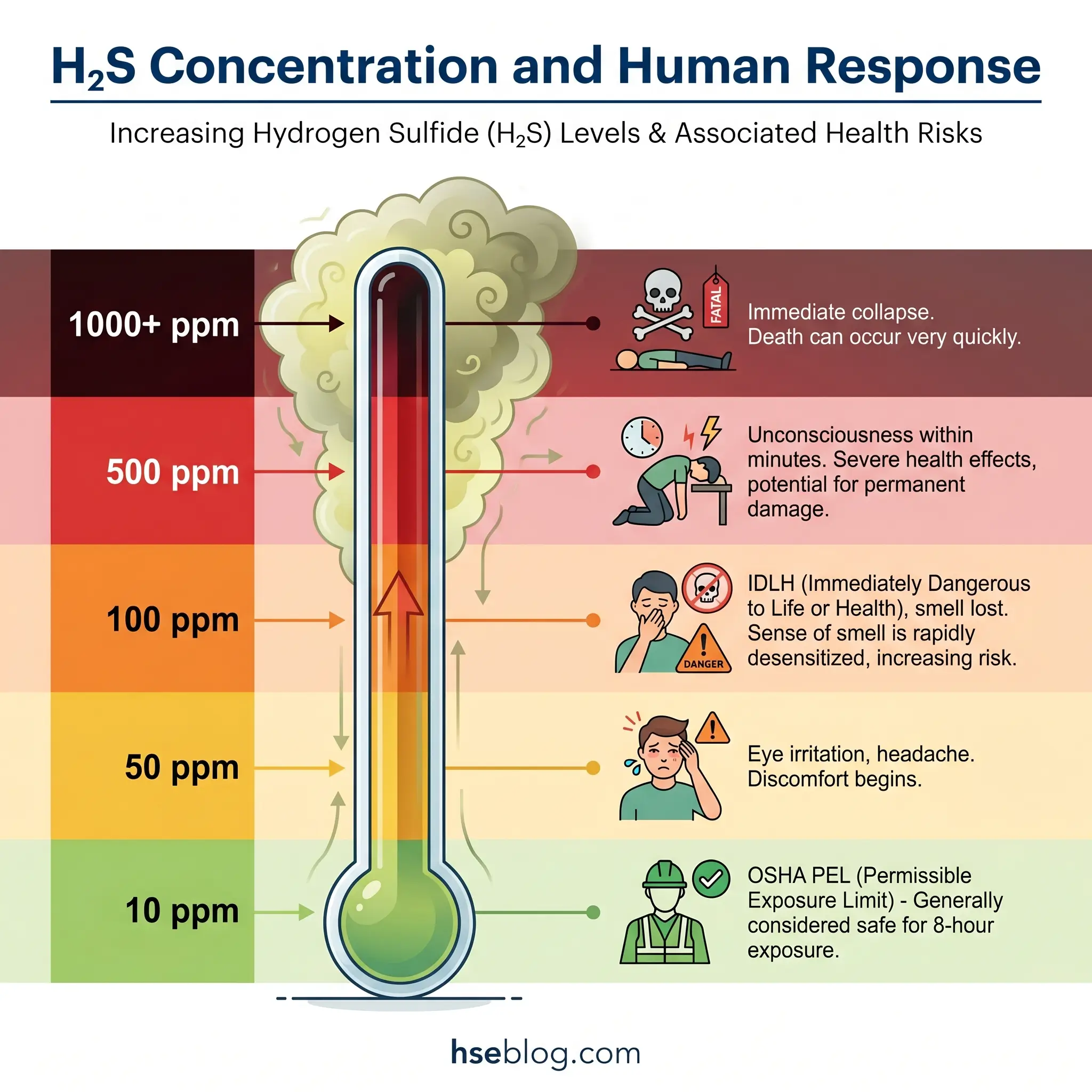
Hazard 2: Hydrogen Sulfide (H₂S) and Toxic Gas Exposure
H₂S earns its own hazard section because its lethality profile is unlike any other toxic gas on an oil and gas site. OSHA’s permissible exposure limit sits at 10 ppm. NIOSH’s Immediately Dangerous to Life or Health level is 100 ppm. Above 500 ppm, unconsciousness occurs in seconds and death follows in minutes without intervention. What makes H₂S genuinely dangerous, though, is the biology: at concentrations around 100 ppm the olfactory nerves are paralysed within a few breaths, and the characteristic “rotten egg” warning smell vanishes. Workers have walked into lethal atmospheres convinced the gas had cleared because they could no longer smell it.
Sour service — gas streams containing significant H₂S — is common across drilling, production, gas processing, and certain refining units. On a sour gas plant, the entire design basis shifts. Metallurgy changes, relief headers are sized differently, and the operating philosophy treats H₂S as a primary design hazard rather than a co-contaminant.
The engineering layer is dense. Fixed continuous monitors at process unit and perimeter locations feed both the control room and plant-wide alarm systems. Personal four-gas monitors, calibrated daily and worn at the breathing zone, give each worker their own atmospheric alarm. Process systems are enclosed and vented through scrubbers or flares rather than to atmosphere. Ventilation is engineered for a gas heavier than air — extraction at low level, not at ceiling level, because H₂S will accumulate in sumps, pits, and basements.
On the administrative side, ANSI/ASSE Z390.1 sets the baseline training standard for H₂S-exposed workers. Pre-job briefings for sour service make clear where the wind is coming from, where the muster points are, and who the buddy is. Atmospheric monitoring sequences before any entry — lower explosive limit first, then oxygen, then toxics — are drilled until they become habit. The single rule that saves the most lives: if a monitor alarms, you leave the area, upwind, immediately. You do not lift your mask to check if the reading looks plausible.
PPE for H₂S is split between working protection and escape protection. Self-contained breathing apparatus is worn for any entry where atmospheres may exceed the threshold limit value. Escape respirators — typically five- or fifteen-minute hoods — are issued to workers in low-concentration sour zones so they can reach fresh air if concentrations climb unexpectedly. Muster points are always upwind, and the wind sock location is a non-negotiable design feature.
Hazard 3: Blowouts and Loss of Well Control
Macondo 2010 remains the reference case for blowouts because it condensed every lesson the industry had accumulated since Piper Alpha into a single, visible event. Eleven people died. The blowout preventer did not seal. The cement job had not been verified. The negative pressure test had been misread. The bow-tie failed comprehensively, front to back.
Well control is built on a two-barrier philosophy. The primary barrier is drilling fluid — mud weight calculated to exceed the formation pore pressure and hold back hydrocarbons. The secondary barrier is the blowout preventer stack: a stacked arrangement of annular preventers, pipe rams, shear rams, and blind rams sitting on the wellhead, ready to close the well if the primary barrier is lost. Neither barrier is sufficient alone. Both must be demonstrably functional before drilling resumes after any change.
The sequence that turns a well control event into a blowout is a kick — unplanned influx of formation fluid into the wellbore — that goes undetected until hydrocarbons reach surface. Early kick detection is the single most important skill on a drilling rig. Pit volume changes, mud return flow anomalies, drilling break (sudden increase in rate of penetration), and gas units on the mud logger’s chart are all warning signs a competent driller reads continuously.
Engineering controls are the BOP stack itself, specified and tested under API RP 53, plus choke and kill manifolds, mud gas separators, and real-time pore pressure and downhole condition monitoring. BOP stack testing — weekly function tests, periodic full pressure tests — is not a paperwork exercise. A BOP that fails its pressure test has to be pulled and repaired before drilling continues, regardless of schedule impact.
Administrative controls begin with well control certification. Every driller, toolpusher, and rig manager holds current certification through IWCF or IADC WellCAP, with recertification on a defined cycle. Management of change procedures cover any deviation from the approved well design. API RP 59 covers well control operations practices. API RP 75 establishes the safety and environmental management programme structure that sits above well-specific procedures.
Emerging practice is shifting the bow-tie further to the left through inherent risk reduction. Managed pressure drilling maintains bottom-hole pressure within a narrow window by controlling surface backpressure — the kick becomes physically harder to take in the first place. Automated kick detection systems using real-time drilling data analytics are cutting detection time in drilling trials from minutes to seconds.
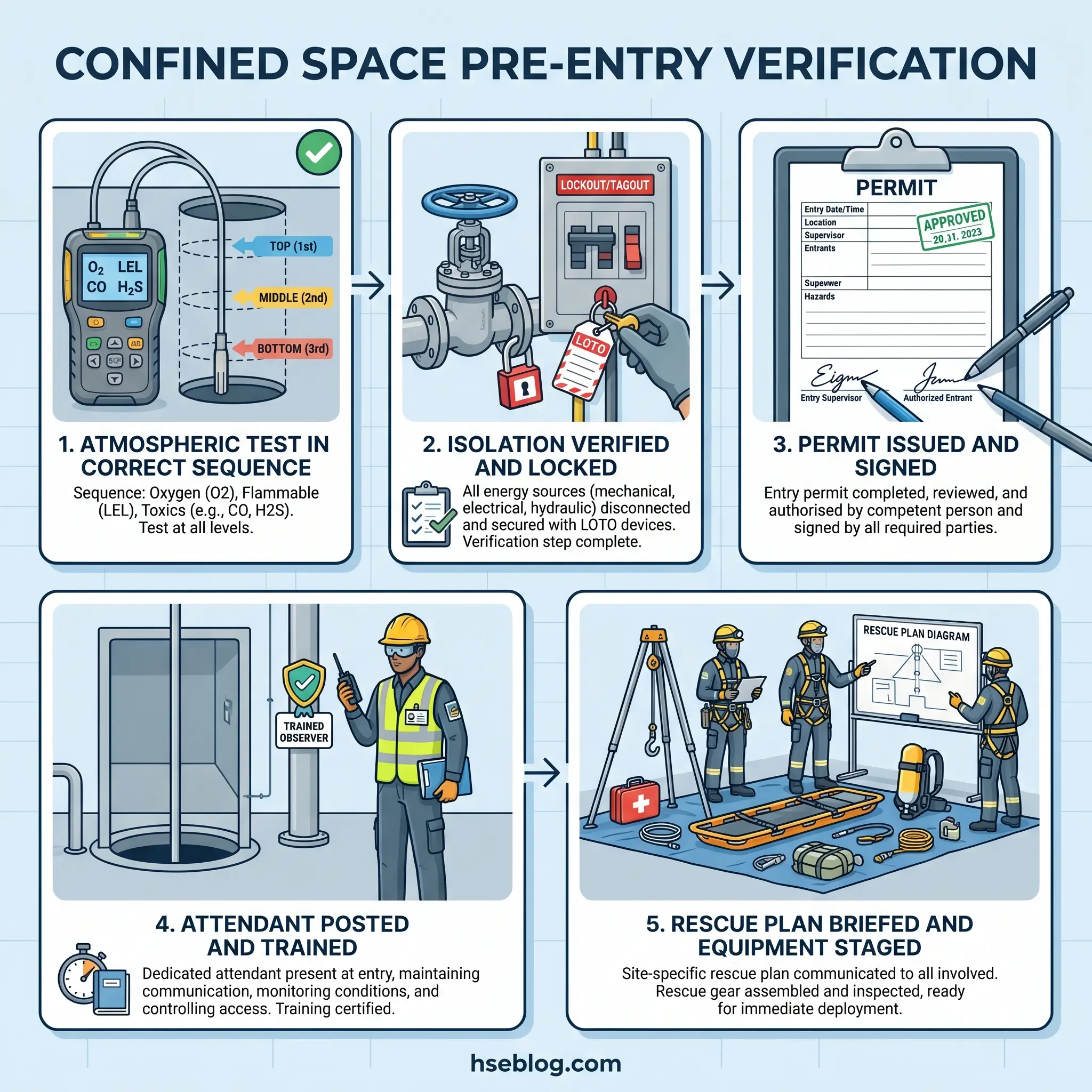
Hazard 4: Confined Space Entry Incidents
Oil and gas has more permit-required confined spaces than almost any other industry. Storage tanks, reserve pits, mud tanks, separators, vessels, sumps, excavations deeper than four feet, and the interiors of process columns and exchangers all qualify. The fatality pattern that haunts this hazard is the rescuer fatality — an entrant goes down, a coworker sees it, enters without respiratory protection, and the incident count doubles. NIOSH data on confined space fatalities has shown for decades that roughly half of confined space deaths are would-be rescuers.
Confined space hazards fall into three categories. Atmospheric hazards — oxygen deficiency below 19.5%, flammable atmospheres above 10% of the LEL, and toxic concentrations above the PEL — are the leading killers. Engulfment hazards include loose product in a storage tank, water in an excavation, or sludge in a separator. Configuration hazards arise from converging walls, sloped floors, or restricted access points that trap a worker or impede rescue.
The control architecture is tight and well defined. Engineering: forced ventilation, atmospheric monitoring with data logging, mechanical isolation of feed lines, de-energisation of agitators and internal equipment. Administrative: a written permit-required confined space programme under OSHA 29 CFR 1910.146 (or the Confined Spaces Regulations 1997 in UK operations), pre-entry atmospheric testing in the correct sequence, a trained attendant stationed outside who cannot be reassigned, entrants with defined identification and duration limits, and — critically — a written rescue plan that does not rely on improvised response.
Rescue is the barrier most commonly weakened by reality. A rescue plan that says “call emergency services” is not a rescue plan. A compliant programme has either an in-house rescue team drilled on the specific entry or a contracted rescue provider pre-mobilised on site with the appropriate equipment. The standing rule on every site worth working on: no entry begins until rescue capability is present, tested, and briefed.
PPE for confined space work is driven by the atmospheric test results. Supplied-air respirators are required whenever atmospheres cannot be verified safe for the full duration of the work. Full-body harnesses with retrieval lines allow non-entry rescue where space geometry permits. Communication — radio or hard-wired — is continuous between the entrant and the attendant.
Hazard 5: Motor Vehicle and Transportation Incidents
Most HSE professionals new to the sector underestimate this hazard until they see the fatality data. Highway vehicle crashes cause roughly four of every ten oil and gas extraction worker fatalities in the United States — the single leading cause of on-the-job death in the upstream segment. CDC and OSHA data have held steady on this figure for more than a decade. A worker is far more likely to die driving between a well site and a crew change than doing any task at the well site itself.
The contributing factors are specific to the industry’s operating pattern. Remote locations mean long drives, often on unfamiliar rural roads with inconsistent surface conditions. Shift patterns push fatigue into the driving leg of the day — the most dangerous hours are the commute after a twelve-hour tour. Heavy loads, trailer-towing, and vehicles poorly maintained by the contractor crew add mechanical risk. Weather exposure in drilling regions is unforgiving.
Engineering controls on vehicle risk have matured rapidly. In-vehicle monitoring systems record speed, harsh braking, harsh acceleration, seat belt use, and driver hours. Rollover protection and electronic stability control are now baseline specifications. Collision avoidance and driver fatigue detection systems — originally aerospace technology — are on new fleet vehicles across major operators.
Administrative controls rest on the IOGP journey management standard, which remains the most developed framework in the industry. Every journey above a threshold distance or risk tier is planned, registered, and monitored. Hours-of-service compliance under DOT FMCSA (or the equivalent in other jurisdictions) is enforced through driver logs. Defensive driving certification is mandatory for any employee driving on company business. Fatigue management programmes set maximum tour lengths and minimum rest periods between driving legs.
The organisational layer is often the missing one. A fatigue policy that exists on paper but is undermined by schedule pressure does nothing. In my experience, the sites that have genuinely cracked vehicle safety are those where the operations manager will delay a rig move rather than let a fatigued driver start a six-hour journey. Culture eats procedure whenever the two disagree.
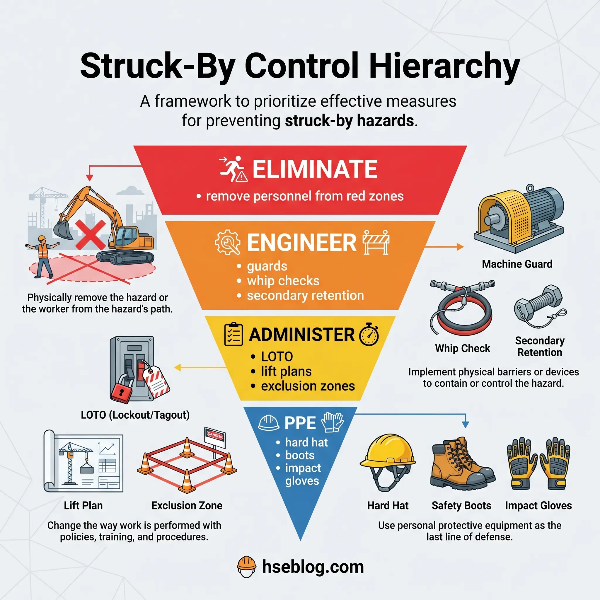
Hazard 6: Struck-by, Caught-in, and Caught-between Incidents
OSHA’s IMIS database is clear: three of every five on-site fatalities in oil and gas extraction come from struck-by, caught-in, and caught-between mechanisms. This hazard cluster is the on-site equivalent of what vehicles are to the commute.
The sources are everywhere on a rig floor or process unit. Rotating wellhead equipment — top drives, kelly drives, rotary tables, mud pumps, agitators. Pipe handling — drill pipe, casing, tubulars being racked, laid down, or made up. High-pressure lines — mud lines, choke lines, hydraulic lines where failure converts stored energy into kinetic energy in milliseconds. Lifting operations — crane loads, derrick loads, cathead-powered lifts. Dropped objects — anything from a tool to a stand of drill pipe falling from height onto the working floor below.
Engineering controls start with machine guarding under OSHA 29 CFR 1910.212 — fixed guards on belts, pulleys, gears, and any rotating component accessible to a worker. Whip checks on high-pressure hoses prevent the hose end from becoming a projectile if the connection fails. Secondary retention for tools at height — lanyards, tethers, tool buckets — prevents the dropped object scenario. Crane load paths are engineered and enforced; lifting operations over live process units require a documented lift plan and a dedicated lift supervisor.
Administrative controls are anchored by the lockout/tagout programme under 29 CFR 1910.147, the red zone concept that defines exclusion zones around rotating equipment and lifting operations, and lifting plans that identify the load, the path, the crew, and the emergency stop procedure. The DROPS (Dropped Objects Prevention Scheme) industry initiative has produced the Reliable Securing guidance used across the majority of rigs and platforms globally.
PPE is both expected and limited: hard hats to ANSI Z89.1 Type II, steel-toe boots, impact-rated gloves, and safety glasses. None of it stops a dropped stand of drill pipe or a whipping hose. The engineered and administrative barriers have to hold.
Hazard 7: Falls from Height
Derrick monkey boards, racking platforms, tank tops, process unit platforms, exchanger structures, and crown blocks create a continuous fall exposure profile across oil and gas work. The distinction that separates mature fall protection programmes from weak ones is the ordering of controls: fall prevention first, fall arrest second. Fall arrest is a mitigative barrier, not a preventive one. A worker hanging from a lanyard has already had a serious incident — the next thirty minutes decide whether it becomes a fatality.
Engineering controls prioritised correctly: permanent guardrails around elevated work areas, engineered access platforms for routine work locations, fall-through protection on grating where a worker could otherwise drop to a lower level, and travel-restraint systems that physically prevent a worker from reaching an unprotected edge. Only when these are not feasible does fall arrest enter the conversation.
Administrative controls follow jurisdiction. OSHA 29 CFR 1926 Subpart M covers construction at heights above six feet; 29 CFR 1910 Subpart D covers general industry at four feet. The UK’s Work at Height Regulations 2005 require a hierarchical approach explicitly — avoid the work at height if possible, then prevent falls, then mitigate the consequences. Harness inspection is a specific gap on many sites. A full-body harness has a fall rating that assumes it is in good condition; visible damage, a dropped-object impact, or a previous arrest event all take it out of service.
Rescue from suspension is the control point most commonly missed. Suspension trauma — orthostatic intolerance caused by pooled blood in the legs while hanging motionless in a harness — can cause loss of consciousness within minutes and fatality shortly after. A competent rescue plan defines who performs the rescue, what equipment is staged, and what the time window is — typically no more than six minutes from arrest to recovery.
PPE consists of full-body harnesses certified to ANSI Z359.11 or EN 361, shock-absorbing lanyards sized for the available clearance, self-retracting lifelines for variable-height work, and, increasingly, trauma relief straps built into the harness for use if rescue is delayed.
Hazard 8: Uncontrolled Hazardous Energy and Electrical Faults
“Hazardous energy” covers more than electricity. Any energy source capable of causing harm when released unexpectedly qualifies: electrical (stored in capacitors, live circuits, induced current), hydraulic (pressurised fluid systems), pneumatic (compressed air and gas), pressurised process (live hydrocarbon lines), thermal (hot surfaces, steam systems), stored mechanical (springs under compression, raised loads), chemical (reactive materials), and gravitational (any raised mass that can fall).
Lockout/tagout under 29 CFR 1910.147 is the foundational procedure, but a competent LOTO programme has to identify and isolate every applicable energy source. A pump that has its electrical supply locked out but still has pressure on the discharge side is not isolated. A hydraulic line that has been de-energised at the HPU but has an accumulator downstream is not isolated. The verification step — attempting to start the equipment and confirming it does not operate — is where shortcut cultures get exposed.
Engineering controls include positively-isolating valves (double block and bleed for hydrocarbon systems), lockable disconnects on electrical systems, pressure bleed points at isolation boundaries, and physical removal of spool pieces for long-duration shutdowns. For electrical work in classified areas, equipment must carry appropriate Ex certification. Installation in a Zone 1 area without intrinsically-safe or flameproof protection is both an electrical violation and a DSEAR/ATEX violation.
The overlap between electrical safety and hazardous area classification is a grey zone where incidents happen. An electrician replacing a luminaire in what they think is a Zone 2 area, but which has drifted into Zone 1 because of a process upset, creates an ignition source at exactly the wrong moment. Control-of-work systems have to tie permits to current hazardous area classification drawings, not to drawings that are three revisions out of date.
Administrative controls include LOTO programmes themselves, electrical safe work practices under NFPA 70E (or IEC 60364-4 and its derivatives internationally), arc flash risk assessments for switchgear work, and hazardous area drawing control.
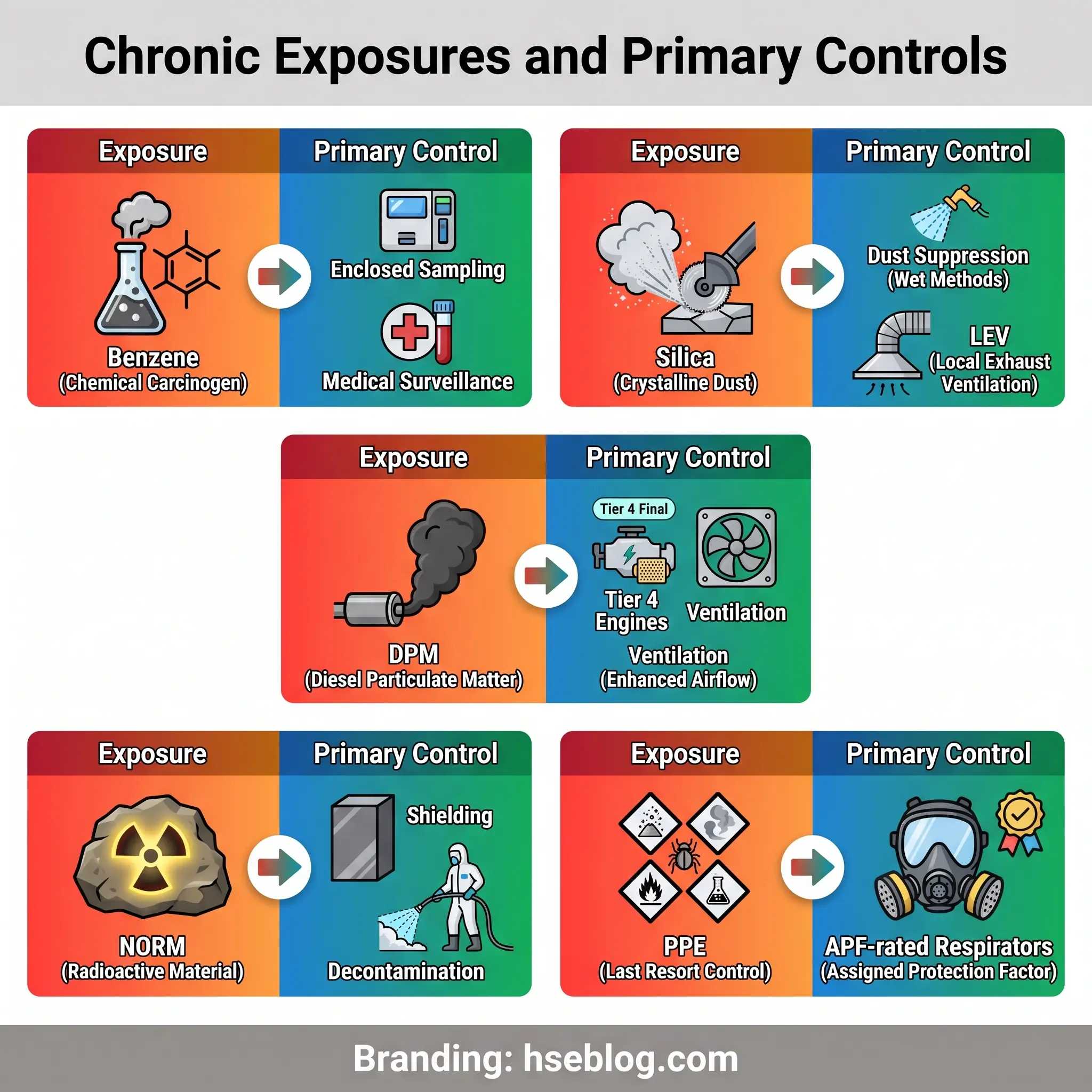
Hazard 9: Chemical and Occupational Health Exposures
Beyond H₂S, oil and gas workers face a chronic exposure profile that causes disease rather than acute injury. The health consequences often manifest years or decades after exposure, which is why the administrative rigour around chemical control is disproportionate to the visible risk at any single shift.
- Benzene is present in crude oil, produced water, and a range of refining streams. OSHA 29 CFR 1910.1028 sets a 1 ppm PEL, with mandatory medical surveillance above the action level. Refinery tank gauging, produced water handling, and certain lab analyses are the commonly-cited exposure scenarios.
- Respirable crystalline silica emerged as a major hazard with the growth of hydraulic fracturing. Frac sand transfer, thief hatch operations, and sand movers in high-wind conditions generate respirable dust far above the OSHA 29 CFR 1910.1053 PEL of 50 µg/m³ as an 8-hour TWA. Engineering controls — enclosed transfer systems, dust suppression, local exhaust ventilation — are the primary response, with respiratory protection as the last layer.
- Diesel particulate matter exposure in field operations comes from generators, drilling engines, and support vehicles. Emerging research increasingly classifies DPM as a Group 1 carcinogen, which has pushed operators towards Tier 4 engines, electric drilling packages, and enclosed cab positive-pressure ventilation.
- NORM — naturally occurring radioactive material — concentrates in scale, sludge, and deposits inside production equipment. Pipe rattlers, tank cleaners, and scale disposal workers can accumulate significant exposure without controls. Management follows jurisdiction-specific radiation protection requirements and ALARP dose reduction.
Across all of these, the administrative framework is the COSHH regime in the UK (or its international equivalents under OSHA 29 CFR 1910.1200 Hazard Communication, GHS-aligned), underpinned by safety data sheet management, written exposure assessments, biological monitoring where applicable, and health surveillance programmes tied to exposure history. Engineering controls — enclosed processes, local exhaust ventilation, wet methods for dust — are the primary defence. PPE is last: appropriate-APF respirators, chemical-resistant gloves matched to the specific chemical rather than generic nitrile, face shields for splash exposure.
Hazard 10: Environmental Releases, Spills, and Atmospheric Emissions
Safety and environmental protection are inseparable in oil and gas. A spill is a regulatory event, a community exposure event, and — depending on the scenario — a fire or toxic event. The same barriers that prevent a fatality usually prevent a release, which is why the ten-hazard list cannot be closed without this category.
Scenarios span the segments. Upstream: well-site releases, produced water spills, storage tank overflows. Midstream: pipeline ruptures, marine transfer spills, rail derailments. Downstream: tank farm releases, process unit flaring events, fugitive emissions from valves, flanges, and seals. Atmospheric releases include methane leaks — now a central ESG concern — volatile organic compound fugitives, and flare inefficiency where incomplete combustion releases unburned hydrocarbons.
Engineering controls are the heart of environmental protection. Secondary containment — bunds around storage tanks sized to hold 110% of the largest tank volume — is the single most effective control on catastrophic spill consequences. Leak detection and repair (LDAR) programmes use optical gas imaging cameras, Method 21 detectors, and increasingly satellite and drone-based methane monitoring to find fugitive emissions. Vapour recovery units capture hydrocarbons that would otherwise vent. Automated shut-off valves close pipelines remotely if pressure anomalies indicate a rupture. Spill containment booms and pre-staged response equipment sit at every marine transfer point.
Administrative controls in US operations centre on Spill Prevention, Control, and Countermeasure plans under 40 CFR 112, reinforced by Oil Pollution Act 1990 requirements for facility response plans at significant storage sites. UK offshore operations work to Oil Pollution Emergency Plans under the OPRC regime and, for the North Sea region, OSPAR convention requirements. Methane emissions are increasingly regulated in their own right — EPA’s OOOOb/c rules, EU methane regulation, and voluntary commitments under the Oil and Gas Methane Partnership 2.0 all tighten the reporting and control expectations.
The ESG dimension has lifted methane from a housekeeping concern to a board-level issue. Satellite monitoring now makes every major emitter publicly visible, and investor scrutiny on methane intensity is reshaping capital allocation across the sector. What was a safety-and-environment issue five years ago is now a safety, environment, and license-to-operate issue.
Integrating the Top 10: A Barrier-Based Approach to Control
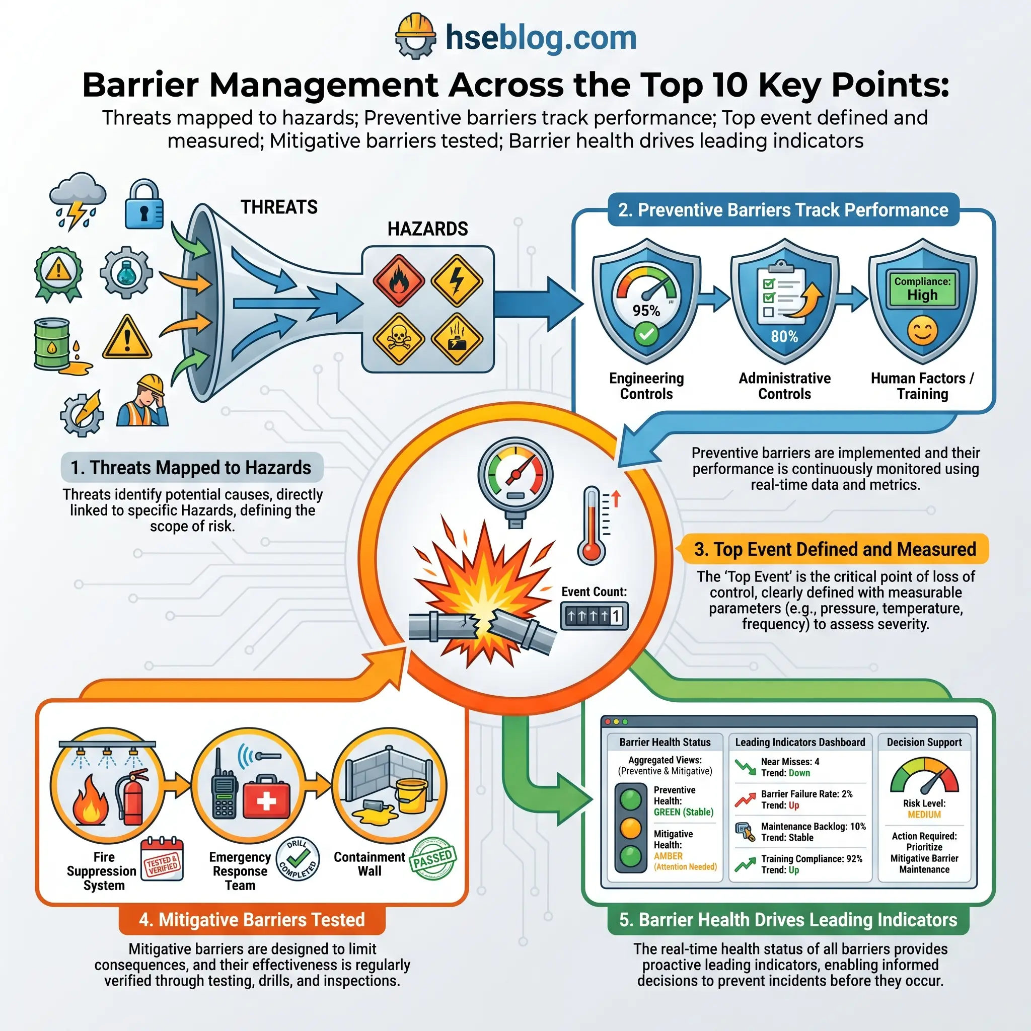
Ten hazards addressed in isolation is a hazard catalogue. Ten hazards managed together is a safety management system. The bridge between the two is barrier management, and the most widely-adopted expression of it is the bow-tie method.
The bow-tie forces three disciplines. First, it separates preventive barriers (threat-to-top-event) from mitigative barriers (top-event-to-consequence) — you cannot substitute one for the other. Second, it makes barrier degradation visible: if a barrier is missing, weakened, or compromised, the bow-tie shows exactly which threat paths are now exposed. Third, it assigns ownership: every barrier has a performance standard and a named accountable person.
Barrier management is measurable in a way that control lists are not. A barrier health indicator tracks the condition of critical barriers over time — gas detector availability, ESD function test pass rates, relief valve test intervals, competency assurance coverage. A declining barrier health indicator is a leading signal of rising risk long before it shows in incident data.
This is where leading and lagging indicators become more than jargon. API RP 754 defines Tier 1 (most severe process safety events) and Tier 2 (less severe) as lagging indicators — they tell you what has already happened. Tier 3 (challenges to the safety system — relief valve activations, safe overrides) and Tier 4 (operating discipline and management system indicators) are leading. IOGP Report 456 built on this framework with a structured set of process safety KPIs. Operators who track leading indicators and act on them see fewer Tier 1 events. Operators who only track Tier 1 events learn after the fact.
Above the barrier layer sits the operating management system — IOGP Report 510 is the reference framework — which integrates risk management, competency, MoC, asset integrity, emergency response, and performance monitoring into a single auditable structure. Beneath all of it sits safety culture: the layer that determines whether the system works on a Tuesday afternoon when the crew is tired and the job is behind schedule.
How AI, Digital Twins, and Connected Workers Are Reshaping Control in 2025–2026
Technology is not a new hazard control layer. It is a way of making the existing layers more reliable, more visible, and faster to act on. The 2025–2026 operating reality is notably different from the pre-digital HSE paradigm, and the gap is widening.
AI-driven predictive maintenance for rotating equipment is moving from pilot to mainstream. Vibration, temperature, and acoustic sensors feed machine learning models that predict bearing and seal failures days to weeks before they occur. The safety implication is straightforward: a seal that is replaced on a scheduled shutdown is a seal that did not release hydrocarbons on a Tuesday afternoon. Unplanned outages fall, which removes a major precursor to release incidents — the chaotic restart after unexpected shutdown.
Digital twins — high-fidelity virtual models of process units, platforms, or complete facilities — are projected to reach roughly 50% adoption among oil and gas operators by 2026, with over 70% currently running pilot programmes. Beyond operational optimisation, the safety applications are significant: process hazard analysis runs against a live model rather than a P&ID, MoC simulation tests the impact of a proposed change before implementation, and emergency response training happens in a virtual replica of the actual facility.
Connected worker platforms are the most visible change on the ground. Mobile permit-to-work systems replace paper permits with geofenced, version-controlled digital records. Digital job safety analyses walk crews through the risk assessment at the worksite rather than behind a desk. Real-time gas monitors tie directly into control room dashboards — an alarm at a worker’s harness triggers response before the worker has finished reacting. Lone-worker alarms combine GPS, motion detection, and man-down sensing to cut rescue time in remote operations.
Computer vision applied to CCTV feeds provides continuous monitoring of PPE compliance and red-zone intrusion, raising alerts when a worker enters an exclusion zone or lifts a hard hat in a designated area. The technology is not perfect — false positives remain an issue — but the direction of travel is clear.
Methane monitoring has moved from LDAR cameras on the ground to drone-mounted OGI, aircraft surveys, and satellite-based monitoring that can detect point-source emissions from orbit. Operators now learn about super-emitter events from third-party satellite data before their own ground teams identify them — a dynamic that is reshaping emissions accountability.
The caveat that matters: every one of these technologies sits on top of the hierarchy of controls, not as a replacement for it. A predictive maintenance algorithm does not eliminate the hazard — it makes the engineering layer more reliable. A digital twin does not substitute for a real HAZOP — it makes the analysis better. The technology layer amplifies the quality of the underlying management system. Applied to a strong system, it raises performance significantly. Applied to a weak system, it produces high-definition visibility of continued failure.
Building and Auditing a Robust Oil and Gas Hazard Management Program
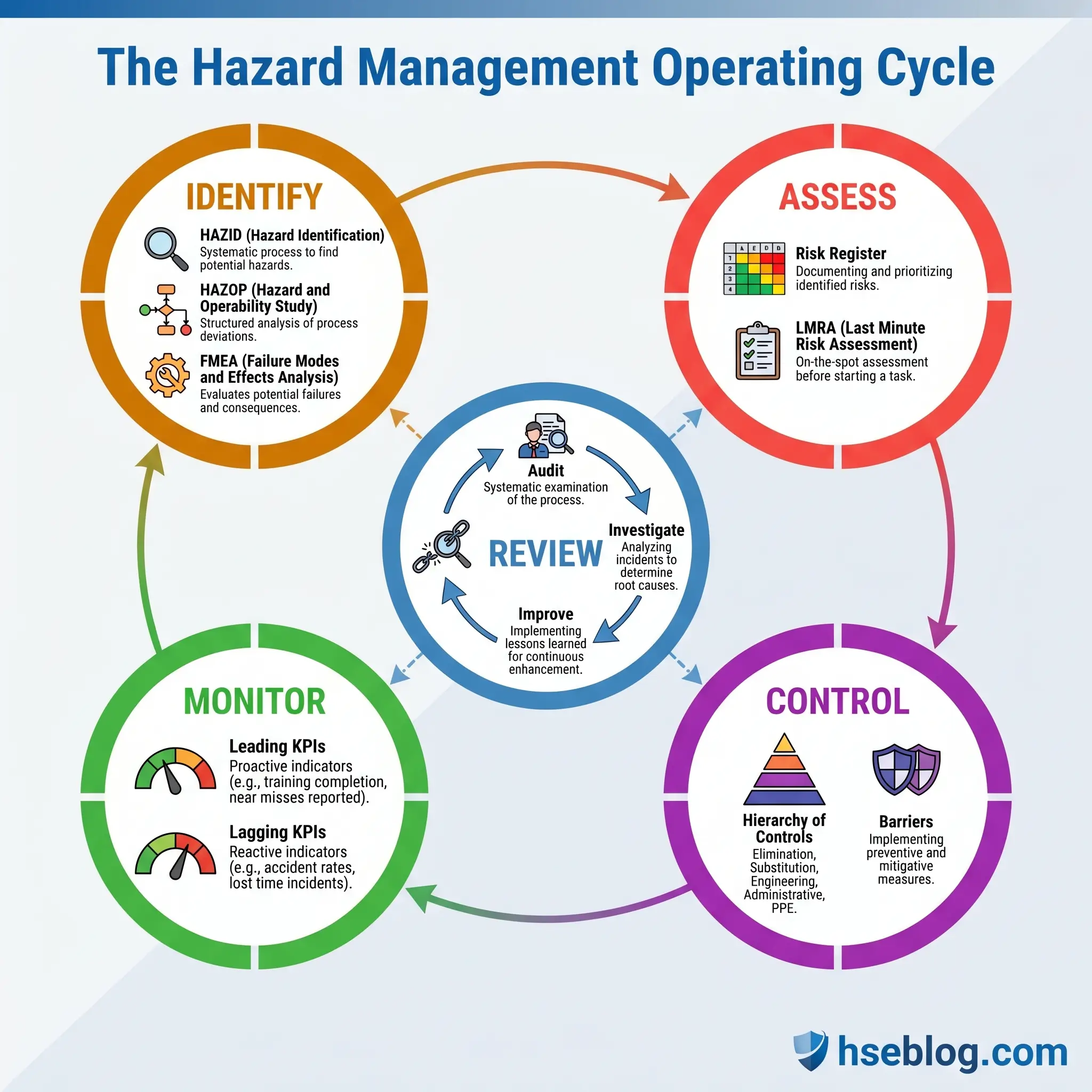
A practitioner framework pulls all ten hazards and their controls into a single operating cycle. The HSE management system lifecycle — identify, assess, control, monitor, review — is the organising principle every operator ultimately converges on.
Hazard identification uses a mix of techniques matched to lifecycle stage. HAZID (Hazard Identification) is used early in project design to surface major hazards. HAZOP (Hazard and Operability) is the workhorse for process plant design reviews. FMEA (Failure Mode and Effects Analysis) targets equipment-level failure mechanisms. What-If reviews are used for modifications and smaller systems. Checklist-based reviews cover standardised, known hazard sets.
Risk assessment works at two levels. Strategic risk assessments populate the corporate risk register and drive resource allocation. Job-level risk assessments — JSA, LMRA (Last Minute Risk Assessment), Take 5 — apply at the worksite and catch the hazards that changed since the permit was issued.
Competence assurance is the causal factor that appears most consistently in IOGP incident analysis and is most often treated as an afterthought. A competent worker knows the hazard, knows the control, and has the authority to stop work when the control is missing. Competence is verified through demonstration, not assumed from certification.
Contractor HSE management is the other dominant gap in IOGP data — contractor fatalities consistently outnumber employee fatalities across reporting operators. Pre-qualification, site-specific induction, integration into the operator’s permit-to-work system, and visible leadership presence at contractor toolbox talks are the minimum controls.
Incident investigation follows structured methodologies. Tripod Beta, Bowtie XP, and ICAM are the three most widely used in oil and gas. The goal is not to find a name to blame; it is to find the failed barriers, the failed management system, and the learning that prevents repetition. Learning loops fail most often at the “implementation” step — recommendations are made, not all are closed out, and the same incident recurs at a different site eighteen months later.
Audit cycle spans self-assessment (daily and weekly), internal audits (typically quarterly to annual), external third-party audits (often against ISO 45001 or operator-specific standards), and regulatory inspections. The audit that finds nothing is usually not a good audit. The audit that finds the right things, at the right depth, with clear closure tracking, is what keeps the management system honest.
Frequently Asked Questions
The Next Decade in Oil and Gas Hazard Control
The direction of regulatory travel across the major jurisdictions is toward tighter process safety expectations, more detailed barrier management requirements, and explicit integration of climate and emissions performance into the safety case. EPA’s methane rules, the EU’s methane regulation, revisions to UK SCR and COMAH guidance, and the slow-building momentum toward a revised US PSM standard all point the same way. An operator building a hazard management programme to the 2019 standard will find themselves short of the 2028 expectation.
The technology curve reinforces that regulatory direction. Digital twins projected to reach roughly 50% operator adoption by 2026, satellite methane monitoring, connected worker platforms, and AI-driven predictive maintenance are converging on a model where barrier health is continuously visible rather than periodically audited. The operators who will lead the next decade are the ones building management systems that can absorb this data without drowning in it — systems that use digital visibility to strengthen the underlying hierarchy of controls rather than as a substitute for it.
The enduring reality, across all of this change, is that the ten hazards in this article will still define the industry’s risk profile in 2035. The tools will improve. The standards will tighten. The causal factors — inadequate hazard identification, weak supervision, degraded barriers, rushed MoC — will remain recognisable to anyone who worked through the investigations of the 2000s. Disciplined attention to oil and gas hazards and control measures, section by section, barrier by barrier, remains the work. The thirty-two people who did not come home in 2024 are the reason it is worth doing well.