
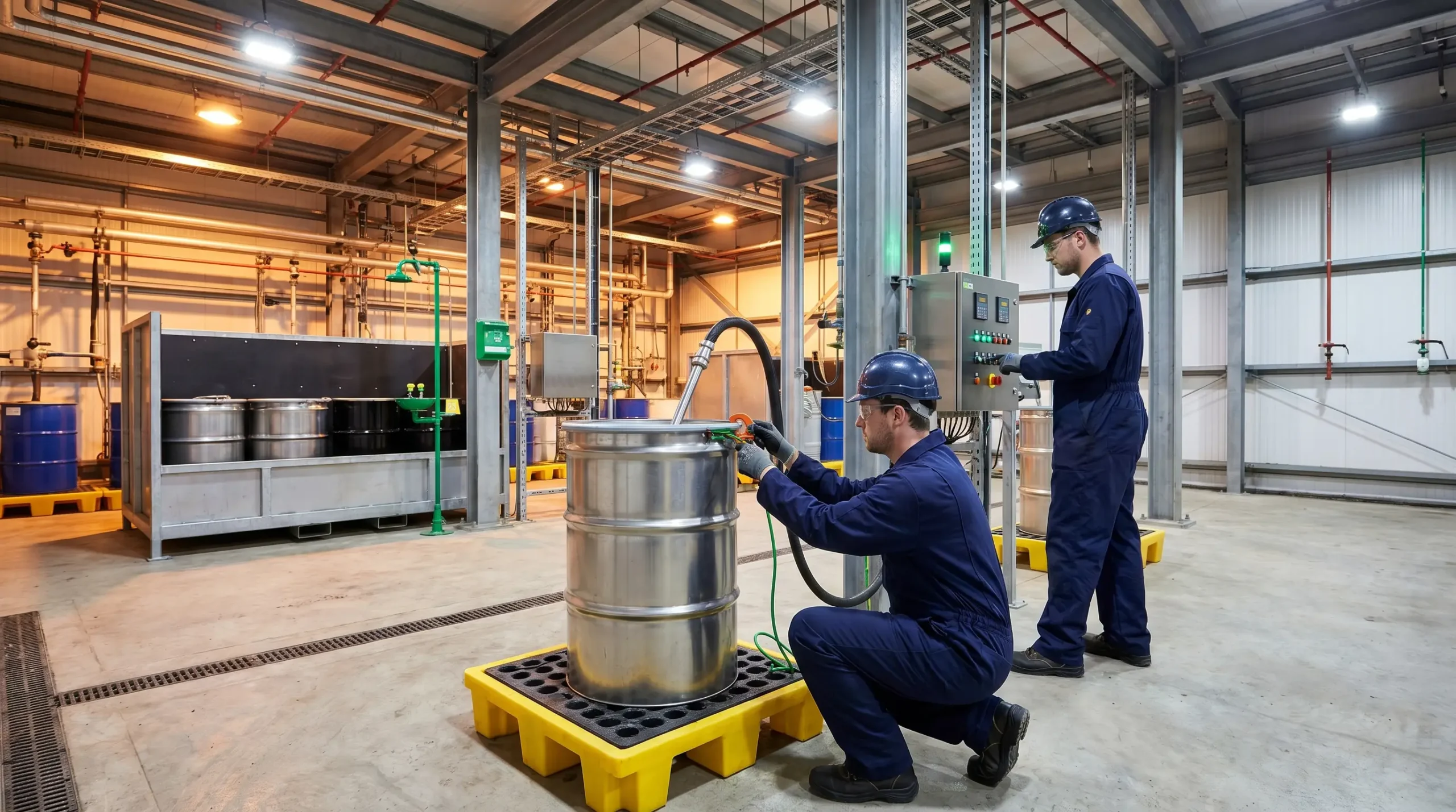
A 200-litre steel drum sits on a scale in the filling bay. A half-conductive hose is lowered through a dip pipe to the bung. When toluene starts moving at four metres per second through thirty metres of pipework, positive and negative charges separate as the fluid shears past the pipe walls. Within seconds the drum’s surface potential climbs past 10,000 volts. Static electricity in flammable environments accumulates exactly this way — quietly, unmeasured, and visible only at the moment it discharges. If the bonding clamp has slipped onto painted metal, the next spark between drum and nozzle carries enough energy to ignite every drop of solvent in the room.
Static electricity rarely appears on the top line of a process hazard analysis. It hides inside operations crews perform a hundred times a day — decanting, blending, filling, sieving, pneumatic transfer. Yet NFPA figures cited in Occupational Health & Safety indicate fire departments respond to roughly 280 industrial incidents involving static electricity each year, and a decade-long analysis of South Korean industrial records in the Journal of the Korean Society of Safety attributes approximately 80 fires and 20 accidents annually to electrostatic causes.
This guide covers what you need to control static electricity in flammable environments: how charges are generated, how they discharge, how their energies compare to the minimum ignition energy of common atmospheres, and which controls actually stop ignition. It also integrates the 2024 revision of NFPA 77 — a reorganization of bonding and grounding requirements that most older guidance has not caught up with.
Why Static Electricity Is a Serious Ignition Hazard
After a near-miss investigation on a solvent blending skid — a flashback through a funnel during the manual decanting of methyl ethyl ketone into a 20-litre pail because the operator had skipped a tangled bonding clip — I started asking audit teams how often they actively searched for electrostatic ignition sources in their routine hazard reviews. The answer was nearly always “rarely, unless the line is non-conductive.” That gap is exactly where this hazard lives.
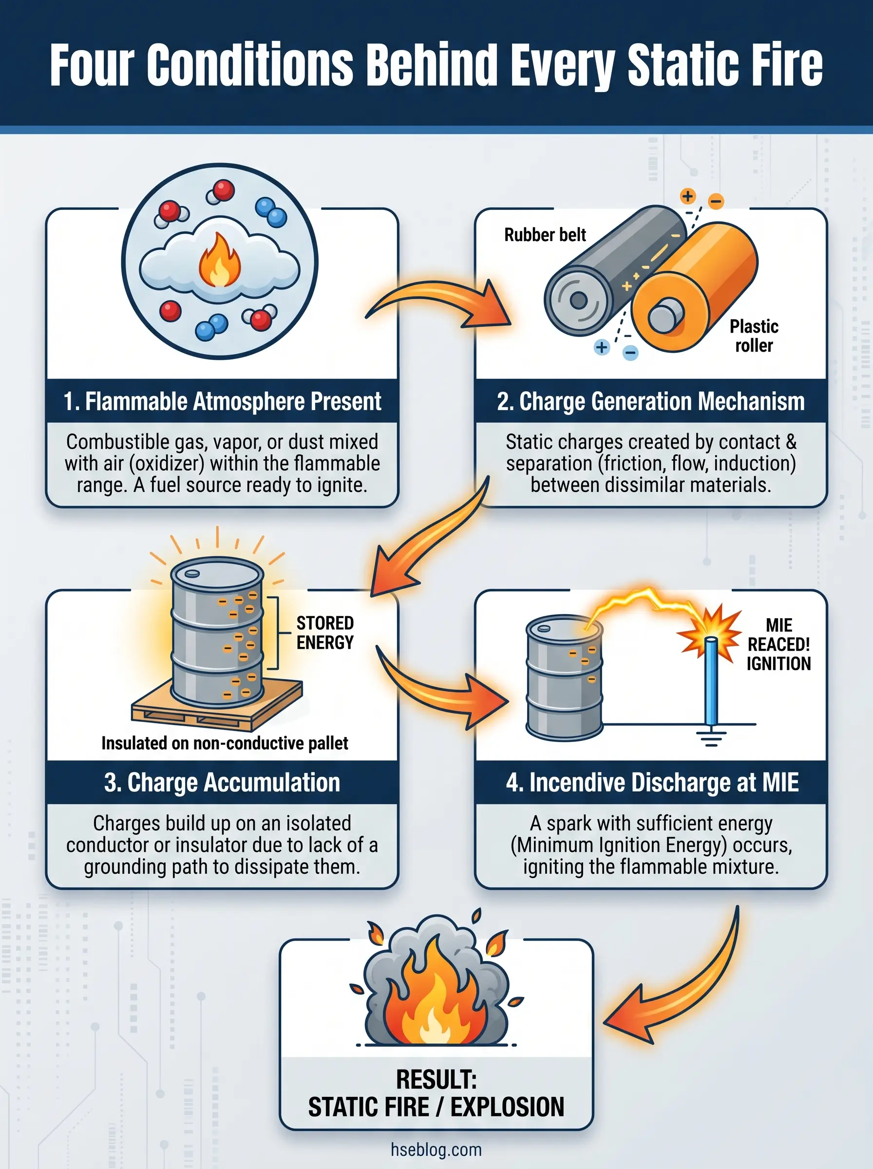
Four conditions must coincide before static electricity produces a fire or explosion:
- A flammable atmosphere within its explosive range — vapor, mist, or dust cloud between its lower and upper flammable limits.
- Charge generation — a mechanism that physically separates positive and negative charges.
- Charge accumulation — an insulated or ungrounded conductor, or a poorly dissipating insulator, that holds the charge instead of draining it.
- An incendive discharge — a release of electrical energy at or above the atmosphere’s minimum ignition energy, at a location where the flammable gas, vapor, or dust is present.
Remove any one and the incident cannot happen. Every control measure in this article rests on that foundation. Dry conditions amplify the problem: relative humidity below 60 percent sharply increases charge retention on most surfaces, and NOAA data cited in Occupational Health & Safety indicates 89 percent of the United States experiences at least seasonal drops into that range — which is why static incidents cluster in the cold, dry months. Static charges also generate no heat, noise, or odor until they release. By the time an operator senses a problem, the decision window has already closed.
How Static Electricity Is Generated in Industrial Processes
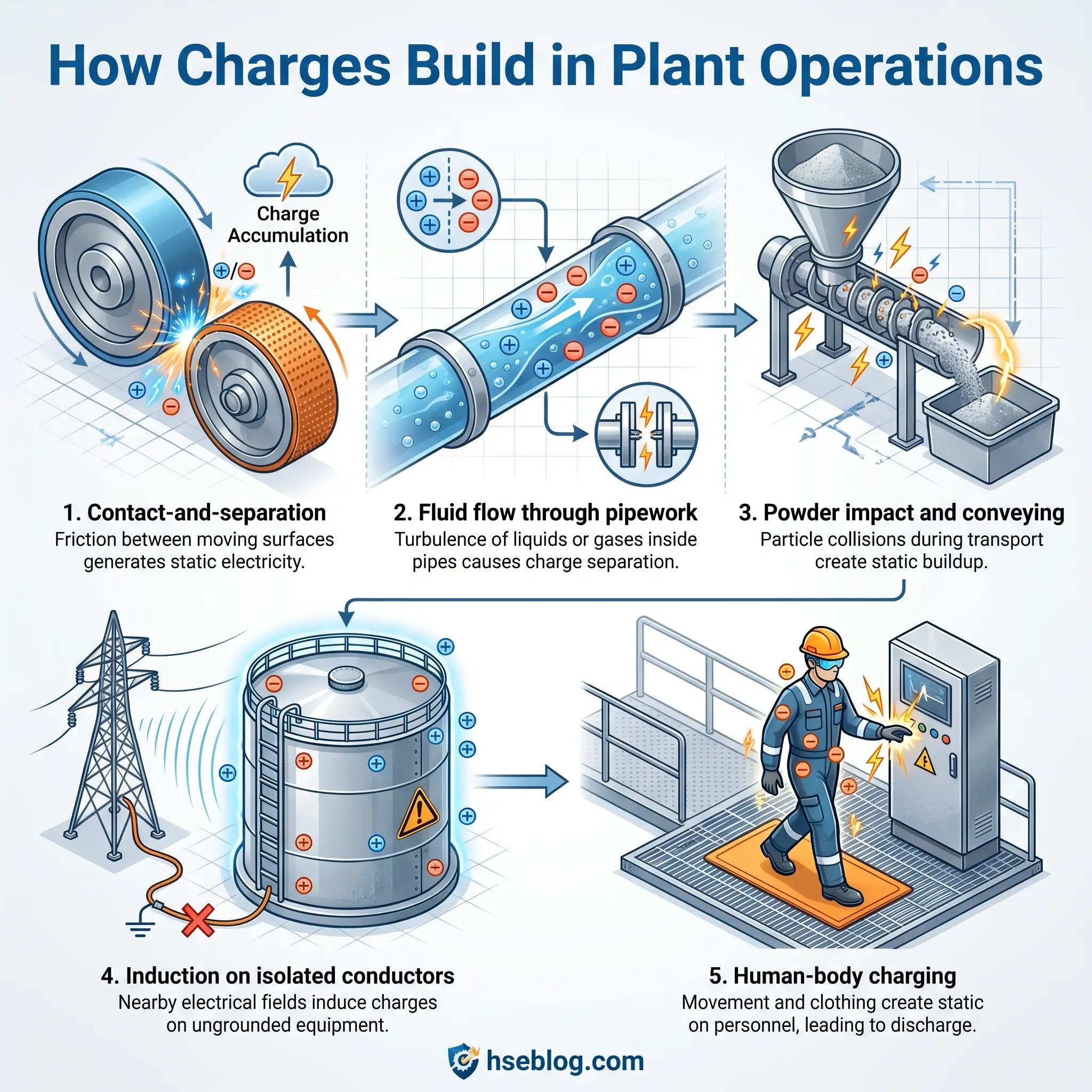
What the physics textbook describes and what happens on the plant floor converge very quickly once you recognize the mechanisms. Charge generation does not require unusual conditions — it rides along with almost every normal material movement. Five mechanisms account for the majority of industrial static problems.
| Operation | Charging Mechanism | Typical Risk Level |
|---|---|---|
| Belt or conveyor on steel pulleys | Contact-and-separation | Moderate (grounded) to high (insulated) |
| Low-conductivity liquid through piping | Flow charging | High — scales with velocity and length |
| Pneumatic powder conveying into silo | Contact, separation, impact | Very high — cone discharges likely |
| Filter element retaining solvent | Flow charging | High — charge on media persists for minutes |
| Operator walking on vinyl flooring | Human-body charging | High if atmosphere MIE <30 mJ |
| FIBC discharge into hopper | Bulking and brush discharge | Very high for Type A/B FIBCs |
Contact-and-separation charging occurs whenever two dissimilar materials touch and part — a polypropylene film unwinding from a roll, a rubber hose sliding out of a coupling, a plastic liner separating from a bulk bag. Flow charging dominates in liquid transfer: non-conductive liquids such as toluene, hexane, kerosene, and most solvents carry charge with them, and the effect grows with flow velocity, pipe length, and the presence of filters or narrow orifices. Powder handling charging is often the most intense, because every particle collision transfers electrons; pneumatic conveying, sieving, micronizing, and silo loading all generate high charge densities. Induction charging builds on an ungrounded conductor — a metal pail sitting on a plastic stool near a charged drum — without direct contact. Human body charging develops when a person walks on insulating floors, slides along upholstery, or removes synthetic garments in dry conditions.
The Five Types of Electrostatic Discharge and Their Ignition Energies
A 10,000-volt potential on a drum tells you nothing about whether an ignition will actually occur. What matters is the type of discharge that releases that potential and how much energy it delivers. Five discharge types dominate industrial incidents, and their energies span nearly four orders of magnitude.
| Discharge Type | Typical Energy | Atmospheres at Risk | Where It Occurs |
|---|---|---|---|
| Spark | 1–10 mJ and above | Almost all gases, vapors, and most dusts | Between ungrounded conductors |
| Brush | Up to ~4 mJ | Gases and vapors; some sensitive dusts | From charged insulating surfaces to grounded conductors |
| Propagating brush | Up to ~1,000 mJ | Nearly all gases, vapors, and dust clouds | On thin insulating coatings over grounded metal |
| Corona | <0.1 mJ | Generally non-incendive | Intentionally used in static eliminators |
| Cone (bulking) | 10–100 mJ | Sensitive organic dusts and hybrid atmospheres | Inside silos during powder filling |
Spark discharges come from ungrounded conductive objects — an isolated metal drum, a disconnected nozzle, a tool in an operator’s hand. Because all stored energy releases through a single low-resistance path, even a modest charge produces an incendive spark. Brush discharges are limited to roughly four millijoules because they originate on insulating surfaces and only release the charge in the small area around the approach point — still enough to ignite low-flash-point solvents such as acetone, toluene, or methanol, well above their MIE of about 0.25 mJ. Propagating brush discharges are the rarest and the most dangerous; they require a thin insulating layer (paint, plastic lining, or coating) bonded to a grounded conductor, and they can release up to a thousand millijoules in a single flash, enough to ignite nearly any gas, vapor, or dust cloud. Corona discharges bleed charge slowly through sharp points — the principle behind static eliminators — and carry energies too low to ignite most atmospheres. Cone discharges, also called bulking brush discharges, occur inside filling silos as the charged powder heap redistributes; they are the primary ignition concern for combustible dust operations.
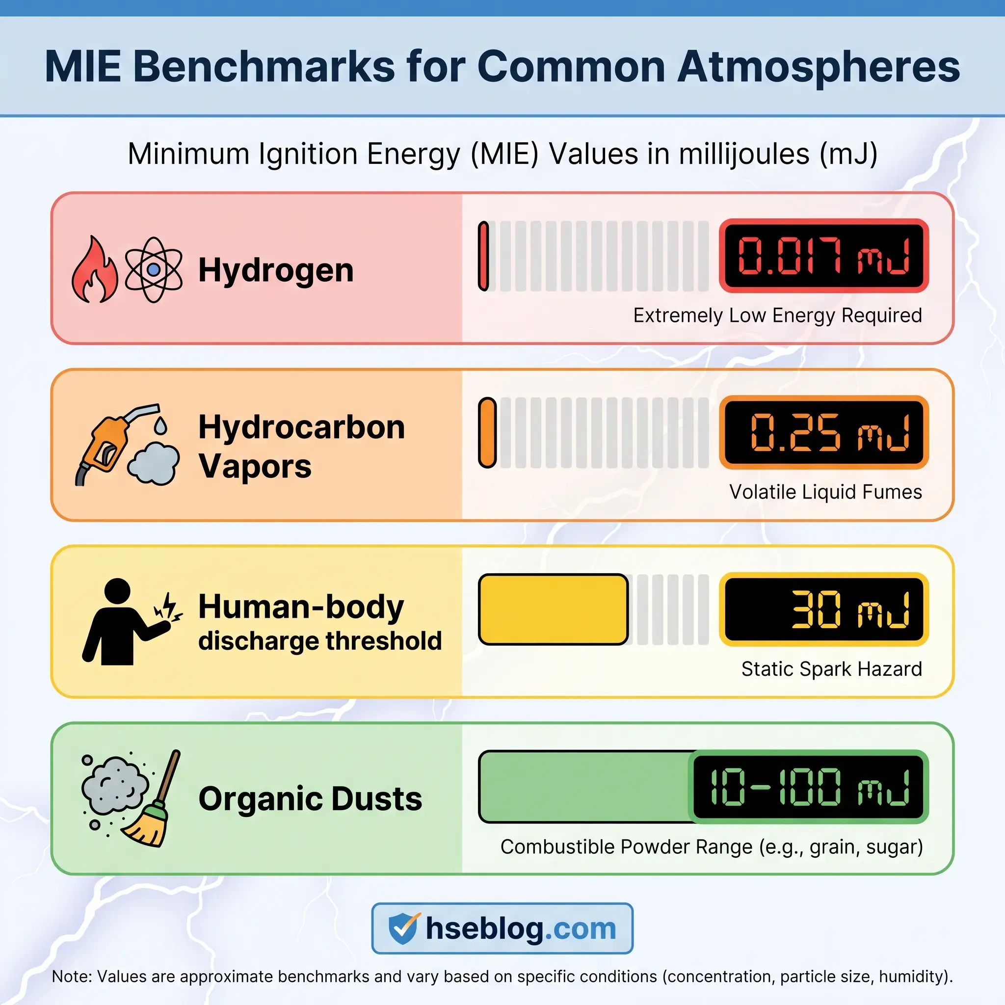
Minimum Ignition Energy (MIE): The Metric That Determines Real Risk
Ignition credibility reduces to a single comparison: does the expected discharge energy exceed the atmosphere’s minimum ignition energy? MIE is measured in millijoules per ASTM E582 for gases and vapors and ASTM E2019 for dust clouds; values are published in safety data sheets and standards, or determined by laboratory testing for novel materials. A representative MIE table clarifies why some atmospheres are forgiving and others are not.
| Atmosphere | Approximate MIE | Notes |
|---|---|---|
| Hydrogen | ~0.017 mJ | Ignited by almost any discharge |
| Acetylene | ~0.019 mJ | Extremely sensitive |
| Saturated hydrocarbon vapors (hexane, heptane, toluene) | ~0.25 mJ | Spark discharges always incendive |
| Diethyl ether, carbon disulfide | 0.2–0.5 mJ | Near-universal ignition risk |
| Typical organic dusts (sugar, flour, wood) | 10–100 mJ | Cone and propagating brush discharges problematic |
| Plastic dusts (polyethylene, polypropylene) | 30 to several hundred mJ | Generally less sensitive |
| Metal dusts (aluminum, magnesium) | 1–50 mJ | Highly variable; hazardous in fine form |
The 30 mJ line matters for a specific reason: human-body discharges cluster below it. Any atmosphere with an MIE under 30 mJ can be ignited by a person wearing insulating footwear on a dry floor. That single threshold drives most of the personnel controls later in this article.
MIE varies with oxygen concentration, temperature, and — for dusts — particle size distribution. Finer particles consistently lower the MIE. Elevated temperatures can drop a dust’s MIE by half or more. Relying on a single literature value without checking the actual process conditions is a common assessment error.
High-Risk Operations Where Static Ignition Most Often Occurs
Most static-related fires trace back to a predictable set of operations. Walk a plant with this list in hand and you will identify the high-probability ignition points before the paperwork catches up.
- Splash filling of flammable liquids above 20 litres — the free-falling stream develops substantial charge and sprays mist into the headspace.
- Tank truck and rail car loading or unloading — high flow rates, long hose runs, and repeated disconnection cycles.
- Drum and IBC filling — especially without dip pipes or when plastic containers are used for Class I liquids.
- Pneumatic conveying and silo filling of combustible powders — cone and bulking brush discharges are almost certain during large transfers.
- Filtration of low-conductivity liquids — charge on the filter medium persists for minutes, and a downstream grounded fitting can trigger a spark.
- Spraying, coating, and paint mixing — atomization generates charge in a mist that is already within flammable limits.
- Vacuum truck operations in petroleum service — historically a disproportionate source of loading-rack fires per API investigation records.
- Tank cleaning with water jets or steam — droplet shearing generates significant charge in an atmosphere that may still hold vapors near the LFL.
- FIBC (bulk bag) emptying — Type A bags retain and then discharge surface charge at the hopper rim.
- Manual decanting from metal to plastic containers — the plastic isolates and accumulates charge the operator cannot dissipate.
One blending facility I supported kept a laminated version of this list on the inside of every filling bay door. When I asked operators why they trusted it more than the SOP, one of them said it told him when to stop and think. That is the point — it names the ten minutes in every shift when static turns from theoretical to imminent.
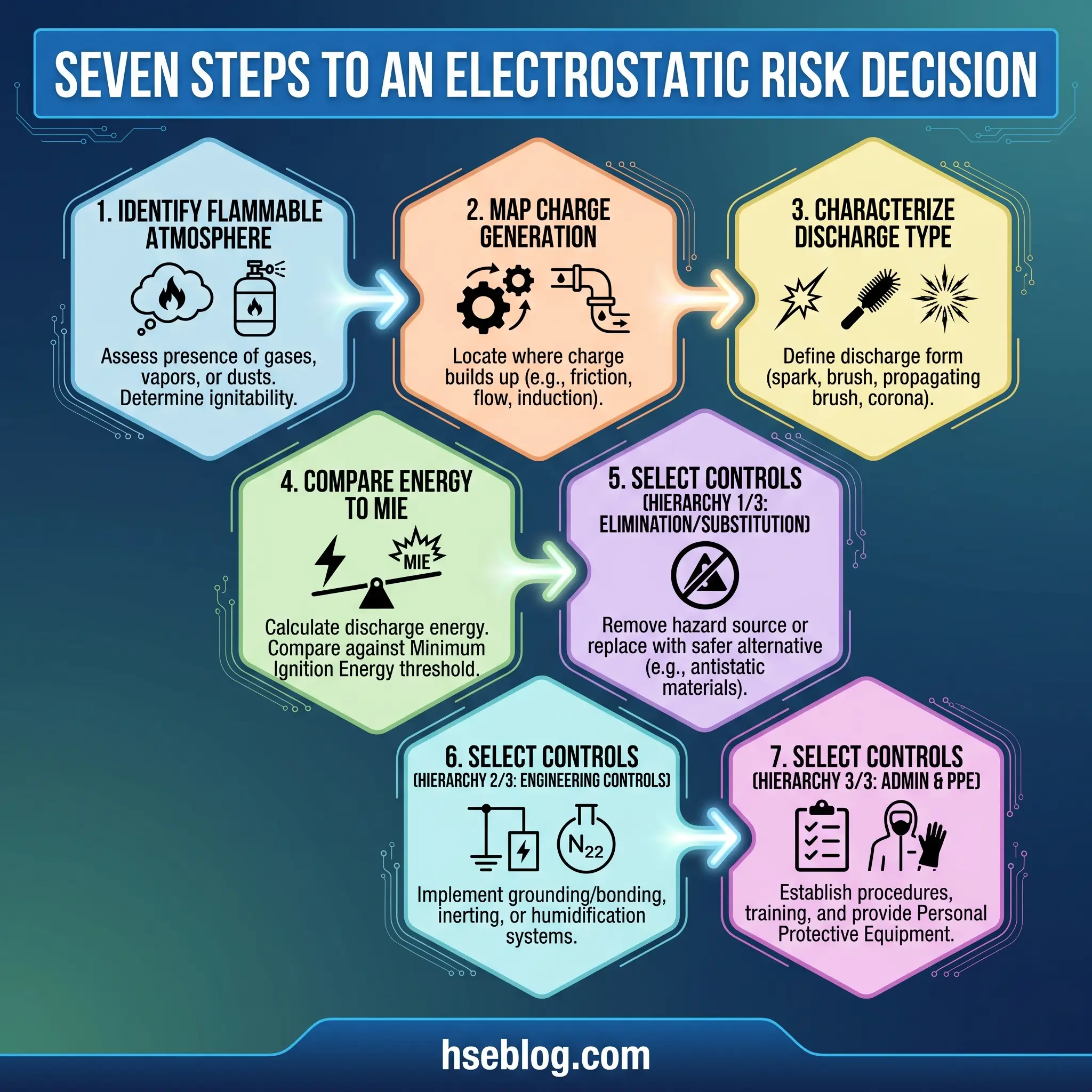
Electrostatic Hazard Assessment: A Step-by-Step Approach
Awareness without a method produces the same result as no awareness at all. A repeatable assessment sequence turns “we thought about static” into “here is how we evaluated it and here is what we did.” The sequence below follows the logic of IEC 60079-32-1 and the NFPA 77-2024 framework.
- Identify where flammable atmospheres can exist. Anchor this to your hazardous area classification drawings; if a location is not classified as Zone 0/1/2 or Zone 20/21/22, an electrostatic ignition there is not credible.
- Map where charges are generated and where they can accumulate. Walk the process and mark every charging mechanism — flow, contact-separation, powder impact, human movement. For each, note whether the charged object is a conductor, an insulator, or an isolated conductor (the most dangerous case).
- Characterize the likely discharge type. A conductive but ungrounded object will produce a spark. A charged plastic surface will produce a brush. A thin insulator on metal will produce a propagating brush. A powder heap in a silo will produce cone discharges.
- Estimate the discharge energy. Use the ranges from the discharge table or, for critical cases, commission laboratory measurement of the actual geometry and materials.
- Obtain the MIE of the atmosphere from the SDS, from authoritative databases, or — for novel powders and blends — from laboratory testing.
- Compare discharge energy against MIE. If credible discharge energy is at or above the MIE, ignition is credible and controls are mandatory.
- Select controls in hierarchy order. Eliminate the atmosphere (inerting), eliminate the ignition source (bonding, grounding, flow control, material substitution), or limit the consequence (explosion venting, suppression).
Documenting each step in the PHA or DSEAR assessment creates the audit trail regulators expect. Missing Step 4 — the energy-versus-MIE comparison — is the single most common deficiency I find in existing assessments.
When to Commission Specialist Testing
Most plants can complete the assessment above using published values. Specialist testing is warranted in four scenarios: the SDS does not provide an MIE, a novel powder blend or new solvent system has been introduced, the geometry creates unusual accumulation risk (long non-conductive ducts, unusual FIBC configurations), or a near-miss suggests the existing controls are not working. Competent providers hold IEC 60079-32-1 testing capability, ASTM E2019/E582 instrumentation, and demonstrable hazardous-area assessment experience. Plain-language reference material from the Canadian Centre for Occupational Health and Safety pairs well with these formal standards for onboarding operations staff.
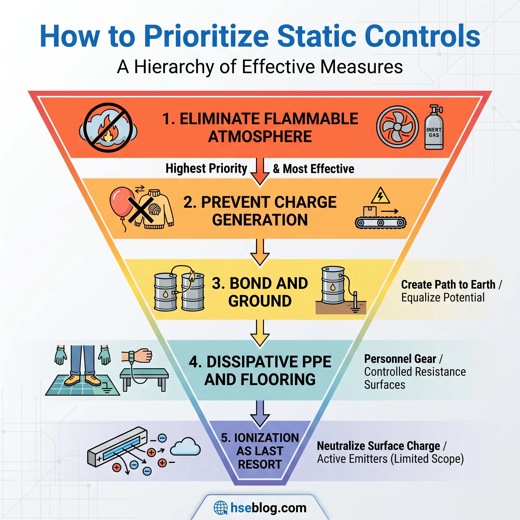
Control Measures: Eliminating or Managing Static Charge
Every effective static control does one of three things: it prevents charge from separating in the first place, it provides a fast path to ground before accumulation becomes dangerous, or it removes the flammable atmosphere so discharges no longer matter. The common mistake is mixing these approaches without understanding which problem each one actually solves.
Preventing charge generation
- Reduce flow velocity of flammable liquids to ≤1 m/s during the splash phase of filling; increase only after the fill pipe is submerged.
- Use dip pipes that reach the bottom of the receiving vessel to eliminate splash and mist generation.
- Avoid unnecessary free-falling streams and atomization near flammable atmospheres.
Providing a path to ground
- Bonding equalizes potential between conductive objects. It does not, by itself, dissipate charge.
- Grounding drains accumulated charge to earth; total resistance should not exceed 10 ohms per IEC 60079-32-1.
- Dissipative flooring and footwear combined provide a controlled path from personnel to earth.
- Conductive or dissipative hoses, piping, and Type C FIBCs replace insulating components that would otherwise accumulate charge.
Removing the atmosphere
- Inerting with nitrogen keeps oxygen below the limiting oxygen concentration and the vapor space below 25 percent of the LFL, per NFPA 69.
- Ventilation and extraction in charging areas reduces the probability of a flammable atmosphere at the discharge location.
Secondary measures
- Humidification above 60–65 percent RH reduces accumulation on some surfaces but is unreliable as a primary control — powder and plastic systems still accumulate dangerous charge at high humidity.
- Air ionization (static eliminators) is effective for continuous web operations — films, paper, plastic — where bonding cannot reach the insulator, but has limited use in enclosed flammable atmospheres.
No single measure covers every scenario. The competent assessment identifies which combination applies to each operation.
Bonding and Grounding: Practical Rules
The distinction between bonding and grounding causes more field confusion than any other electrostatic topic. Bonding connects two conductive objects so they rise and fall in potential together — no spark can jump between them because there is no potential difference. Grounding drains that shared potential to earth. For flammable liquid transfer you usually need both: bond the nozzle to the receiving container, and ground the receiving container to a verified earth point.
Practical rules that hold up in the field:
- Make metal-to-metal contact. A spring-clamp clipped onto painted, oxidized, or coated surfaces may read continuity on a meter and still arc under load. Scrape a bright spot or use a piercing clamp.
- Use braided bonding cables, not coiled wires. Coiled cables hide broken strands; braided cables flex without fatigue and fail visibly.
- Maintain one dedicated electrostatic ground. Share-a-ground arrangements with electrical equipment may meet code for safety grounding but introduce noise and corrosion that degrade the low-resistance path required for charge dissipation.
- Verify continuity before every transfer. On a drum line I supported, adding an active bond monitor reduced documented bonding deviations from roughly 14 percent of transfers to under 1 percent within a quarter.
- Inspect, test, and record. Resistance across the full bonding and grounding path should be tested at intervals matched to the environment — quarterly for outdoor loading racks, annually for indoor filling stations in clean service.
On older installations using a single stainless bolt driven into a concrete floor as the “ground,” I have logged resistance readings north of 200 ohms — electrically useless for electrostatics. A dedicated copper earth rod bonded to the building’s grounding grid, tested with a calibrated earth-tester, is the benchmark.
Controlling Static During Flammable Liquid Transfer
OSHA 29 CFR 1910.106(e)(6)(ii) requires that when Class I flammable liquids (flash point below 100°F / 37.8°C) are transferred by pouring from one container to another, both containers shall be electrically interconnected. This is the law in the United States; ATEX 1999/92/EC and DSEAR 2002 impose equivalent obligations across Europe and the UK. The practical sequence for safe decanting:
- Verify the atmosphere. Confirm the area is zoned appropriately and that the equipment in use meets the zone rating.
- Position and bond the receiving container before opening the source container. Clamp bonding cables to bare metal on both.
- Verify the ground on the receiving container with an active bond monitor or handheld tester.
- Insert a dip pipe or use the manufacturer’s fill tube so the outlet reaches the container bottom.
- Start the transfer at reduced flow (≤1 m/s) until the pipe is submerged, then step up to normal flow.
- Avoid switching tools, opening other containers, or disconnecting cables mid-transfer.
- Break the bond last, after the transfer is complete and the container is sealed.
For Class II and Class III liquids handled at or above their flash points — mineral oil loaded through a heated filter, for example — the same precautions apply because the effective flash point is reached in service. A common audit finding is “unheated” Class II solvents being bonded while the identical product flowing through a steam-jacketed transfer line next door is not.
Hazardous Area Classification and Its Role in Static Control
Static control and hazardous area classification are often treated as separate disciplines; in practice they converge at the equipment-selection level. A Zone 1 specification means ATEX- or IECEx-certified equipment appropriate to that zone, but it also means specific electrostatic restrictions. IEC 60079-32-1:2015 limits the surface area of exposed insulating plastic in Zone 1 to small values — typically under 100 cm² for group IIB atmospheres and under 20 cm² for group IIC — because larger areas can accumulate enough charge to produce an incendive brush discharge.
Zone reference
- Gas and vapor zones: Zone 0 (continuous or long-term presence), Zone 1 (likely in normal operation), Zone 2 (unlikely and short-duration).
- Dust zones: Zone 20 (continuous cloud), Zone 21 (likely in normal operation), Zone 22 (unlikely and short-duration).
Conductive or dissipative flooring, antistatic footwear, and antistatic workwear are required in any zone where the atmosphere’s MIE is below approximately 30 millijoules — which includes essentially every Class I hydrocarbon vapor zone. An area classification drawing that does not include a note on electrostatic requirements is incomplete.
The Human Body as an Ignition Source
A person walking across vinyl flooring in winter conditions can reach a surface potential of 10,000 to 15,000 volts and carry a discharge energy of roughly 10 to 30 millijoules. Compared with the 0.25 mJ MIE of toluene vapor, that is orders of magnitude above the ignition threshold. This is why operators igniting solvent atmospheres as they approach or touch a grounded object is not rare — it is the predictable outcome when personnel controls fail.
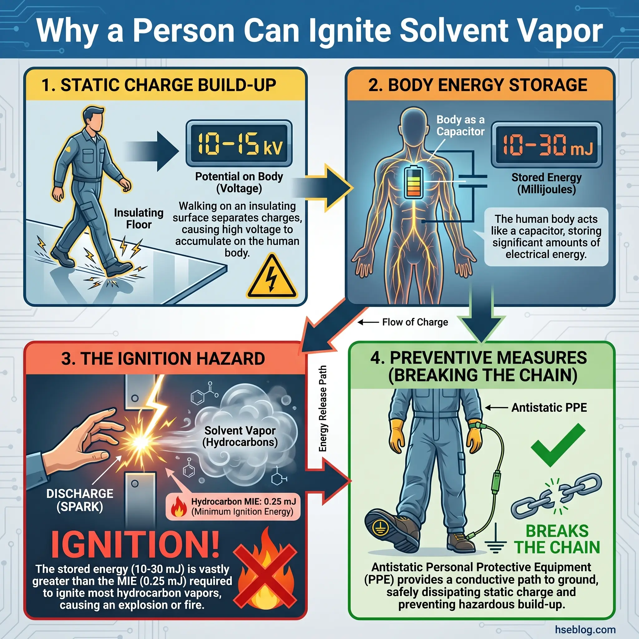
During a safety stand-down at a paint manufacturing line, an operator asked me why I insisted on antistatic coveralls when the fill pumps and drums were already grounded. I walked him to a static voltmeter, had him shuffle across the floor in his regular boots, and touched the probe — the meter read 8.2 kV. Then I asked him to repeat it in the dissipative footwear kept by the entry door. The meter read under 500 V. The lesson landed faster than a briefing slide would have.
Personnel controls that actually work:
- Antistatic or dissipative footwear per EN ISO 20345/20346 combined with dissipative flooring. Boots alone are insufficient if the floor is insulating.
- Antistatic workwear per EN 1149 — no polyester, nylon, or fleece garments inside zoned areas.
- Touch-a-metal-plate stations or personal grounding posts at the entry to filling rooms.
- No clothing changes inside the zone. Removing a fleece over a flammable atmosphere has ignited incidents documented by both HSE UK and NFPA.
- No synthetic container linings or disposable plastic scoops that could isolate a charged operator from ground.
The human body is a credible ignition source for almost every atmosphere handled in a solvent or powder plant. Controls that assume grounded equipment is sufficient — without addressing people — leave the most common path to ignition open.
Regulatory Framework: What the Law and Standards Require
Regulators rarely write prescriptive electrostatic rules; they enforce through general duties and by adopting consensus standards as the benchmark for reasonable precautions. The table below summarizes what applies where.
| Standard / Regulation | Jurisdiction | Key Requirement |
|---|---|---|
| OSHA 29 CFR 1910.106 | United States | Bonding of Class I liquid transfers; precautions against static ignition |
| NFPA 77-2024 | US (consensus; OSHA benchmark) | Recommended practice on static; 2024 revisions to Chapter 7 |
| NFPA 30 | United States | Liquid classification (I, II, III) driving control requirements |
| NFPA 69 | United States | Inerting and explosion prevention systems |
| NFPA 660 (2025 consolidation) | United States | Dust hazard analysis must address electrostatic ignition |
| ATEX 2014/34/EU | European Union | Equipment certification for explosive atmospheres |
| ATEX 1999/92/EC | European Union | Employer duty to assess and control; antistatic PPE |
| DSEAR 2002 | United Kingdom | Regulation 6 risk control; Regulation 7 zoning; Schedule 1 ignition sources |
| IEC/BS EN 60079-32-1:2015 | International | Definitive technical guidance on electrostatic hazards |
| API RP 2003 | International (petroleum) | Tank loading, vehicle grounding, vacuum truck operations |
| IEC 61340 series | International | Resistivity measurement methods for antistatic materials |
NFPA 77-2024, released with a completely reorganized Chapter 7, now distinguishes bonding conductors, grounding conductors, and active bond-monitoring systems as separate technical elements — a change that affects how compliance is documented in the United States. It also adds specific provisions for powder charge relaxation time and expanded guidance on FIBC usage, and any audit relying on the 2019 edition should be updated. Falling short of NFPA 77 guidance without documented justification has supported OSHA citations following incidents. The UK Health and Safety Executive maintains its ATEX and DSEAR guidance as the primary regulatory reference for European operations, and the full NFPA 77 document is accessible via the NFPA standards portal.
The 2025 consolidation of multiple combustible-dust standards into NFPA 660 has brought a related shift: dust hazard analyses must now specifically evaluate electrostatic ignition sources, ending a long pattern in which static control was treated as a footnote to dust-handling safety.
Training and Competency Requirements
Most static-related incidents I have investigated trace back to a trained operator who failed to execute a known control — the bonding clip that was clipped to paint, the fill rate that was opened to full speed too early, the plastic scoop that was used to save a minute. Training matters less for imparting new knowledge than for building the habits that keep existing knowledge in front of the hands.
A competent training structure has three levels:
- Awareness training for all personnel entering hazardous zones — what static is, why they cannot feel it, what clothing and footwear to wear, what to do if bonding cables are missing or damaged.
- Competency training for operators performing flammable liquid transfers, decanting, FIBC handling, or powder charging — practical demonstrations of bonding, flow control, dip-pipe use, and atmosphere checks, with formal sign-off.
- Specialist training for persons conducting DSEAR/ATEX assessments or electrostatic hazard reviews — usually a multi-day program aligned with IEC 60079-32-1, often involving external accreditation.
Annual refreshers are the common standard; mandatory refreshers after process changes or relevant near-misses are more valuable than the calendar-driven ones. Competency records should identify the specific operations each person is authorized for, not generic “static electricity trained” entries.
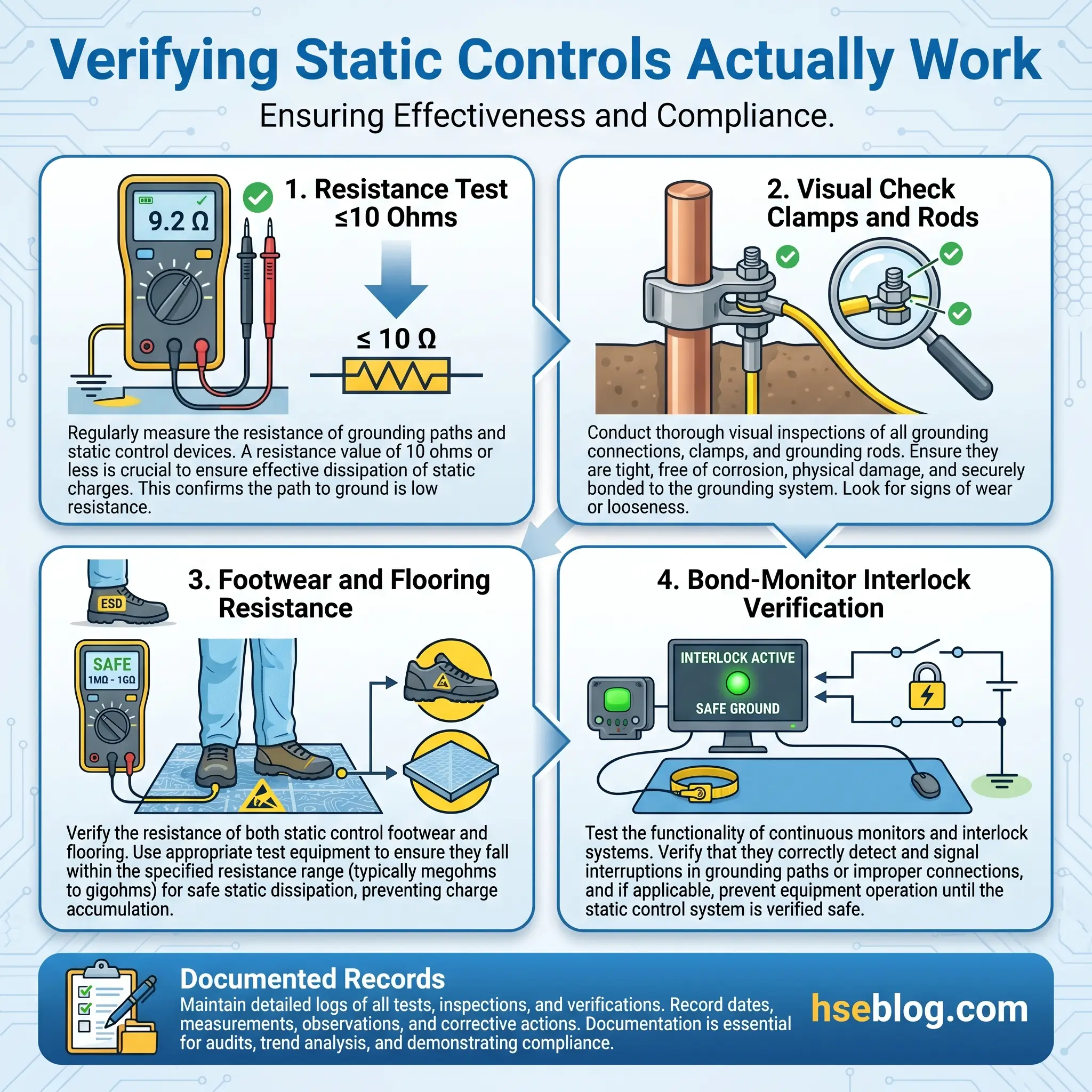
Inspection, Maintenance, and Verification of Static Control Systems
Control systems fail silently. A bonding cable with three broken strands reads continuity until it fails under vibration. An earth rod corrodes inside a concrete floor and no one notices until an annual test reveals 400 ohms. A colleague supervising a solvent-blending facility once found that his building’s entire “grounding grid” was a single copper strap that had separated from its rod three years earlier — every static measurement taken that quarter had been against an open earth.
A working verification program includes:
- Periodic resistance testing of every bonding and grounding path, with pass/fail criteria of ≤10 ohms per IEC 60079-32-1.
- Visual inspection of clamps, cables, and earthing points for paint, corrosion, and mechanical damage — at a frequency matched to the environment (monthly for outdoor loading, quarterly indoors in clean service).
- Footwear and flooring resistance testing per IEC 61340 for sites that rely on them as an ignition source control.
- Active bond-monitor verification on tank truck racks, drum filling stations, and FIBC discharge points, with interlocks that prevent pump start if bonding fails.
- Record-keeping aligned with DSEAR/ATEX documentation requirements — without written evidence, an inspector has no way to accept that the system is maintained.
The inspection program is where compliance either becomes real or stops at the cover page of the binder.
Frequently Asked Questions
Conclusion
Static electricity in flammable environments is moving from a specialist subtopic into the core of modern process safety practice. The 2024 revision of NFPA 77 reorganized how bonding, grounding, and active monitoring are specified, responding to decades of field data showing that “connected the cable” was too vague a standard. The 2025 consolidation of combustible-dust requirements into NFPA 660 now forces dust hazard analyses to address electrostatic ignition directly, ending a long pattern of treating static as a footnote to other process risks.
Expect further movement in two directions over the next several years. Active bond-monitoring — once an oil-and-gas terminal technology — is migrating into smaller chemical, pharmaceutical, and paint operations as the cost of the hardware falls; what was a best-practice recommendation three years ago will be the de facto audit expectation shortly. At the same time, electrostatic assessment is being integrated into digital PHA and HAZOP tools, which is raising the quality of MIE-versus-discharge-energy comparisons that most plants used to approximate or skip.
The short version for any site handling Class I liquids, combustible dusts, or flammable gas mixtures: treat static as an ignition source that is always present and never visible, and build your controls on the hierarchy that actually works — eliminate the atmosphere where you can, drain the charge where you cannot, and never assume a bonded clamp you did not verify this shift is still electrically connected.