
TL;DR
- ~100 psi (7 bar) — the pressure at which hydraulic fluid injection injuries become possible, per HSE-cited research (UK Health and Safety Executive, 2014). Most industrial systems operate 20–50× higher.
- 3 of 5 attempts — the rate at which hydraulic oil at 3,000 psi penetrated welding gloves in a manufacturer-conducted demonstration cited in industry training literature (Construction Equipment magazine).
- 3rd most-cited federal OSHA standard, FY2024 — Control of Hazardous Energy (29 CFR 1910.147), the rule governing hydraulic stored-energy release (US Occupational Safety and Health Administration, 2024).
- 20 January 2027 — the date EU Machinery Regulation 2023/1230 becomes fully binding, replacing Directive 2006/42/EC and adding requirements for cybersecurity and AI-based safety functions (European Commission, 2023).
Hydraulic system safety is the engineering and procedural discipline of preventing injuries from pressurised fluid systems — including high-pressure injection through pinhole leaks, burns from hot fluid, impact from whipping hoses, and crushing from dropped loads. It combines failure-mode prevention, lockout/tagout for stored energy, and emergency medical response for injection injuries.
A hydraulic line carrying 3,000 psi holds an extraordinary amount of energy in a small volume. Sever a half-inch hose at that pressure and the fluid jet will travel several metres before it disperses. Sever it through a pinhole the diameter of a pencil lead, and the jet becomes invisible — narrow enough to slip past a glove and through skin without leaving a wound bigger than an insect bite. The system does not announce its danger. It simply continues to do what it was engineered to do: convert stored pressure into mechanical work, regardless of whether the work is moving a cylinder or perforating a hand.
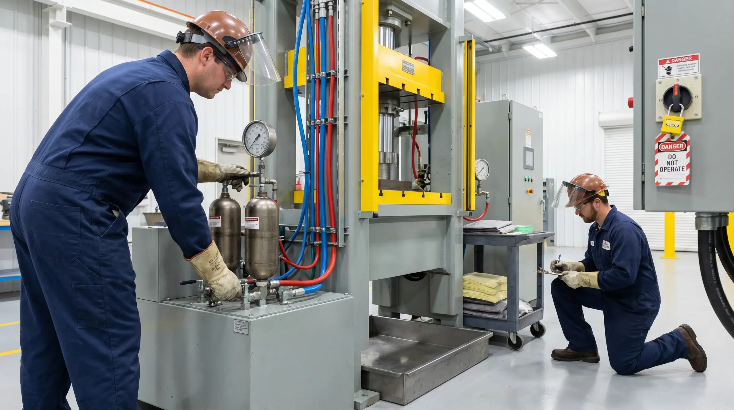
Most plant equipment becomes safe when the power is off. Hydraulic systems do not. Accumulators hold pressure for hours after shutdown. Vertical cylinders hold loads against gravity. Isolated line segments retain charge after disconnection. A worker who treats hydraulic system safety as a sub-section of general machine safety — rather than a discipline with its own energy-control logic — will eventually be wrong about what “safe to service” means. The sections that follow walk through the common failure modes, the controls that interrupt them, the regulatory anchors governing hydraulic work in the US, UK, EU, and globally, and the medical response standard for injection injuries — because the injury that defines this hazard class cannot be managed by prevention alone.
Competent-person caveat: This article provides general HSE knowledge. Life-critical work on hydraulic systems — accumulator servicing, pressure testing, energy isolation, and fitting replacement on charged lines — must be planned and supervised by a competent person with relevant training, jurisdiction-specific authorization, and site-specific risk assessment. The information here does not replace that.
Medical advice disclaimer: Content covering hydraulic injection injuries is for HSE practitioner reference. It is not medical advice. Any worker with a suspected high-pressure injection injury should seek immediate emergency care and request a hand surgeon — even if the wound looks trivial.
Why Hydraulic System Safety Requires Its Own Risk Framework
Hydraulic systems are categorically different from most plant equipment, and the difference is energy density. A small reservoir of fluid under pressure carries the same force-delivery capability as a much larger mechanical or electrical system. Mobile equipment typically runs at 2,000–3,500 psi. Industrial presses operate at 3,000–5,000 psi. Some specialist applications — aerospace, deep-sea, ultra-high-pressure forming — reach 10,000 to 12,000 psi. The penetration threshold for human skin sits around 100 psi.
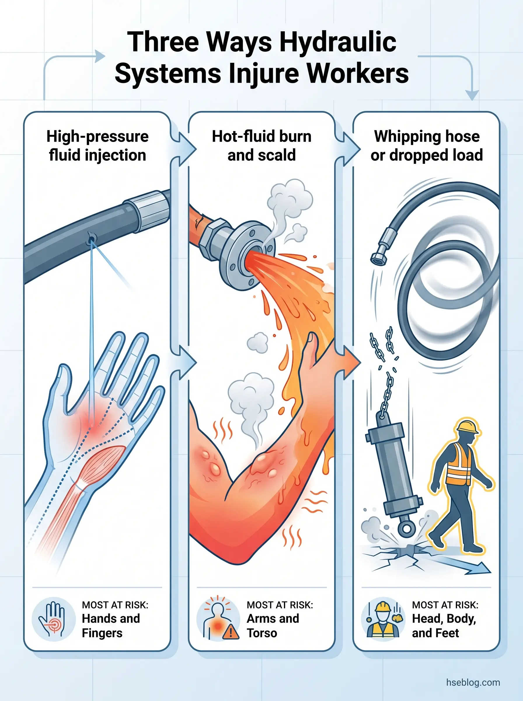
Three injury mechanisms dominate the published incident record. High-pressure fluid injection through pinhole leaks, loose fittings, or quick-disconnect failures is the most underestimated and the most surgically destructive. Hot-fluid burns occur where seal degradation or hose rupture releases oil that has been working at temperatures of 60–80°C in normal operation, sometimes higher under load. Mechanical impact — from a whipping disconnected hose, from a cylinder dropping when its load is no longer hydraulically supported, from a flying fitting under blow-out pressure — accounts for the third group.
The defining characteristic across all three is that the system stores energy independently of the prime mover. Switching off the pump removes the source of new pressure. It does not remove pressure already in the circuit. Accumulators are designed to hold their charge. Vertical cylinders are designed to hold loads. Closed line segments hold whatever pressure was trapped when the valve was last closed. A widely recurring pattern in incident investigations is that lockout/tagout programs treat hydraulic equipment as if shutting down the electrical supply removes the hazard — and miss the accumulators, the vertical cylinders, and the trapped pressure entirely. This article works through both the engineering failure modes and the human-factor controls that close that gap.
The Most Common Hydraulic System Failure Modes
A consistent pattern in the published failure record: what gets recorded in the maintenance log as “pump failure” is almost always a downstream symptom. The actual root cause is usually upstream — in the suction line, the reservoir, the filter, or the fluid itself. Investigators who replace the pump without finding the upstream cause replace it again within months. The failure modes below explain why.
Fluid contamination. Particulate, water, air, and oxidation byproducts together account for the majority of hydraulic failures. Industry sources commonly place this at 80–90% of cases — a figure widely repeated in vendor literature but not traceable to a single peer-reviewed primary source, so it is best treated as directional industry consensus rather than a verified statistic. The mechanism is consistent regardless of which figure is correct: contaminants accelerate component wear, score servovalves, embed in seal faces, and degrade fluid viscosity.
Cavitation and aeration. Both produce noise and pump damage; both are commonly misdiagnosed. They are different failures with different fixes. The next subsection covers them.
Hose and fitting failure. Pinhole leaks, abrasion through cover and reinforcement, improper crimping, and mismatched couplings drive most line failures. ISO/TS 17165-2:2018 governs hose-assembly practice for a reason — the failures listed in its annex track closely with the patterns seen on real equipment.
Seal and gasket failure. Heat-driven elastomer hardening, contamination wear, and fluid incompatibility are the three dominant degradation paths. A seal failure rarely happens in isolation; it usually marks an upstream temperature or contamination condition.
Overheating and viscosity loss. Fluid that runs above its design temperature thins, oxidises, and forms varnish on internal surfaces. Varnish blocks small clearances in servovalves and proportional controls — and once a system has varnished, fresh fluid recontaminates within days unless the surfaces are cleaned.
Pump failure. Treated separately for clarity, but operationally a downstream consequence: contamination wears the pump, cavitation erodes its surfaces, starvation overheats it. The pump is the last component to fail in most failure chains, not the first.
Accumulator-related failures. Pre-charge loss, bladder rupture, and undetected stored pressure during servicing. Accumulators carry their own safety section later — they fail differently from the rest of the circuit, and they kill differently.
Human-factor failures. Wrong fluid grade. Wrong fittings. Wrong pressure setting. Inspection skipped during turnarounds. Every other failure mode in this list has a human-factor variant where the engineering held but the procedure didn’t.
Cavitation vs Aeration: Telling Them Apart
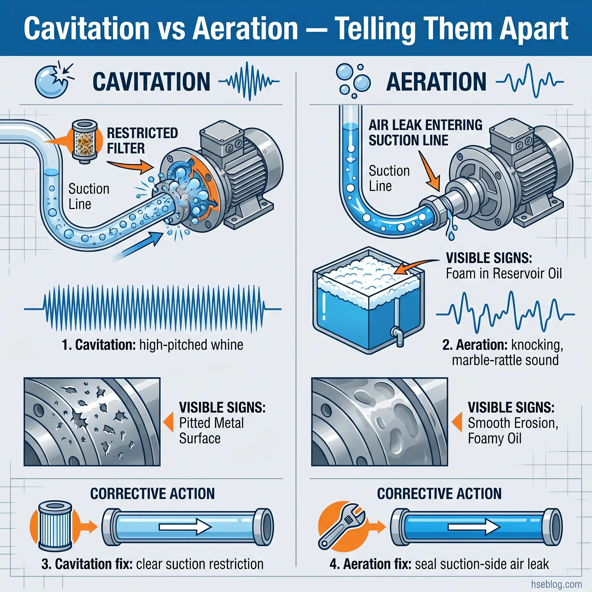
Cavitation is an internal phenomenon: local pressure in the suction line drops below the fluid’s vapor pressure, vapor cavities form, and they collapse violently as they reach the high-pressure side of the pump. The collapse erodes pump surfaces. The acoustic signature is a high-pitched whine. The cause is almost always a suction-side restriction — a clogged filter, a partially closed isolation valve, a reservoir level so low the inlet is uncovered intermittently, or insufficient net positive suction head available (NPSHA) for the pump’s demand.
Aeration is an external phenomenon: air enters the suction line through a defective seal, a loose fitting, or because the suction strainer is exposed at low oil level. The acoustic signature is different — a knocking or marble-rattle sound — and the diagnostic giveaway is foam in the reservoir. Cavitation does not foam the reservoir; aeration does. Replacing a pump diagnosed as “cavitating” when the actual fault is aeration is one of the more common diagnostic mistakes in hydraulic maintenance.
Why Pinhole Leaks Are the Most Underestimated Failure
A pinhole in a pressurised hose is the leak you cannot see. The opening can be smaller than a pencil tip. The fluid exits at velocities high enough to cross several feet of air with the cohesion of a solid jet. The hose looks visually intact; sometimes the only sign is a faint mist in low light, or oil staining on adjacent surfaces with no obvious origin. Workers who run a hand along the line to find the leak are using their hand as the detector. That practice is the most direct cause of injection injury in the published record — which is why the next section starts with the medical standard, not the prevention checklist.
How Hydraulic Injection Injuries Happen — and Why They Are a Medical Emergency
The HSE Safety Bulletin on hydraulic injection injury notes that research has documented injection injuries possible at pressures as low as 7 bar, around 100 psi (UK Health and Safety Executive, 2014). Industrial hydraulic systems run far above this. The penetration is silent, the entry wound is often smaller than a pinprick, and pain is delayed by hours. Workers describe it as a bee sting. They wash the small mark, finish the shift, and present to a clinic the next day with a swollen, discoloured hand that no antibiotic will resolve.
The mechanism inside the tissue is the part that matters for treatment. The injected fluid travels along fascial planes, displaces blood supply, and triggers a chemical inflammatory response that compounds with the mechanical disruption. Hydraulic oils, paint thinners, greases, and water-glycol fluids each carry different toxicity profiles. A peer-reviewed analysis published via PubMed Central reviewing high-pressure injection case literature reports that amputation likelihood is highest with organic solvents and paint thinner — approximately 80% — compared with around 22.5% for grease (PubMed Central, 2019). Hydraulic oil sits between these extremes; the variables that move the outcome are toxicity, time-to-treatment, and injection pressure.
Gloves do not help. Industry training literature reports a manufacturer-conducted demonstration in which hydraulic oil at 3,000 psi penetrated welding gloves in roughly 3 of 5 attempts (Construction Equipment magazine). Gloves protect against burns, abrasion, and incidental fluid contact. They do not protect against a pressurised jet.
The most reliable failure pattern in injection-injury cases is the medical handoff itself. The worker self-presents to a non-specialist clinic. The wound looks like a minor puncture. Antibiotics are prescribed and the worker is sent home. The next presentation, 24–48 hours later, is to the emergency department with developing necrosis. By that point, surgical options have narrowed and amputation rates rise. The interpretive lesson is that the medical handoff is part of the safety control — not just the prevention.
Watch For A hand or arm wound that looks too small to matter, made by something that wasn’t visible at the time of contact, on a worker who was in proximity to a pressurised hydraulic line. Treat as injection injury until proven otherwise.
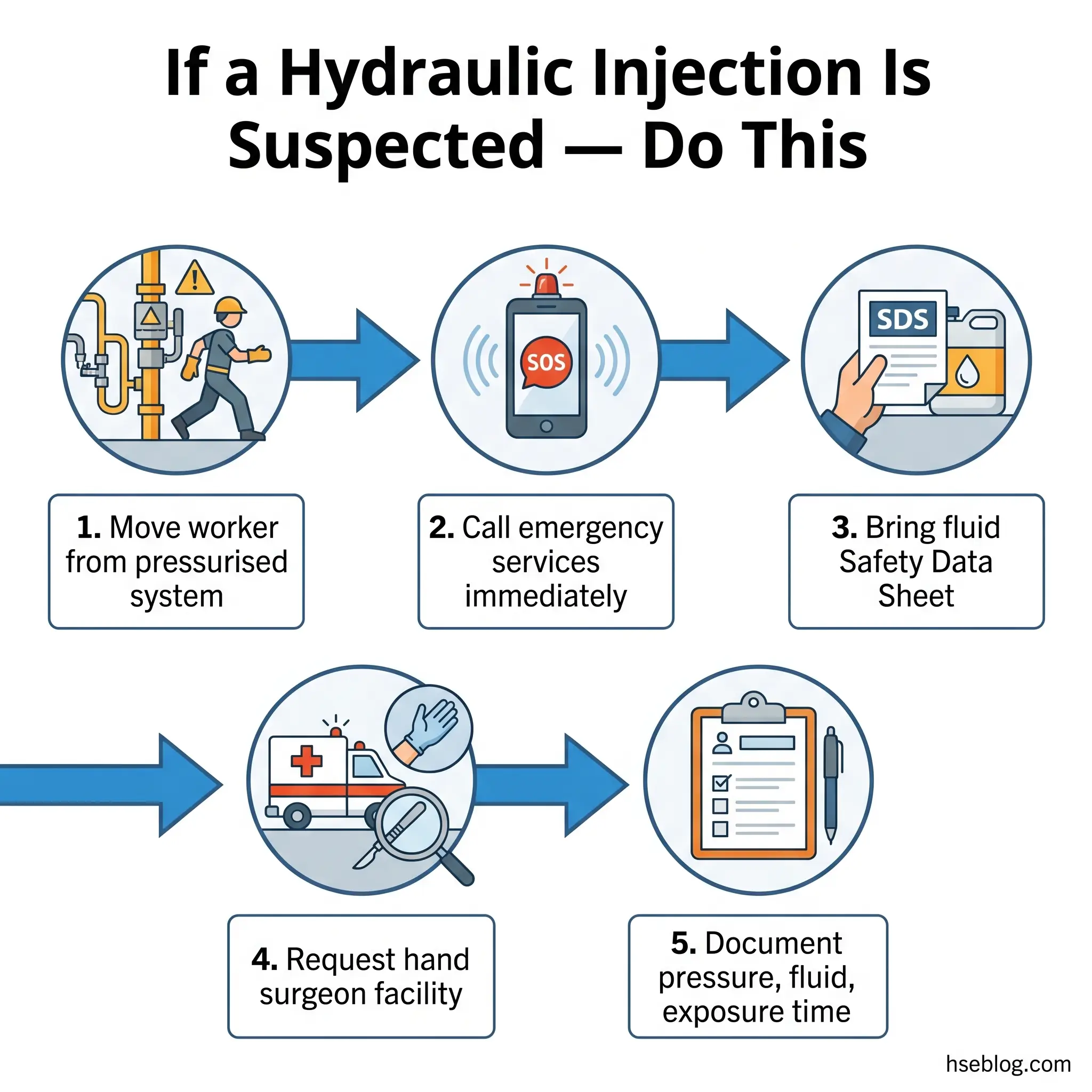
If a hydraulic injection injury is suspected — what the response standard requires:
- Stop work in the area and move the injured worker away from the pressurised system.
- Do not wash, squeeze, or “milk” the wound. Do not apply ice. Do not delay for first aid that does not change the outcome.
- Call emergency services. State explicitly: high-pressure injection injury. Do not say cut or puncture.
- Bring the Safety Data Sheet for the hydraulic fluid. The receiving hospital needs it to assess toxicity.
- Request transfer to a facility with a hand surgeon on call. If the first hospital is not equipped, the receiving facility must arrange transfer — do not accept conservative treatment.
- Document the injection pressure, fluid type, exposure time, and approximate time of injury. The surgical team uses these to plan decompression and debridement.
Safe Practices for Working On Pressurised Hydraulic Systems
OSHA 29 CFR 1910.147(d)(5) requires that all potentially hazardous stored or residual energy be relieved, disconnected, restrained, or otherwise rendered safe before servicing — and that if reaccumulation is possible, isolation verification continues. The clause names hydraulic energy explicitly. The UK equivalent under PUWER 1998, particularly Regulation 19, requires effective means of isolation from all power sources and is the controlling reference for British sites. ISO 4413:2010 is the design-side companion that defines what an isolation point on a hydraulic system should look like in the first place.
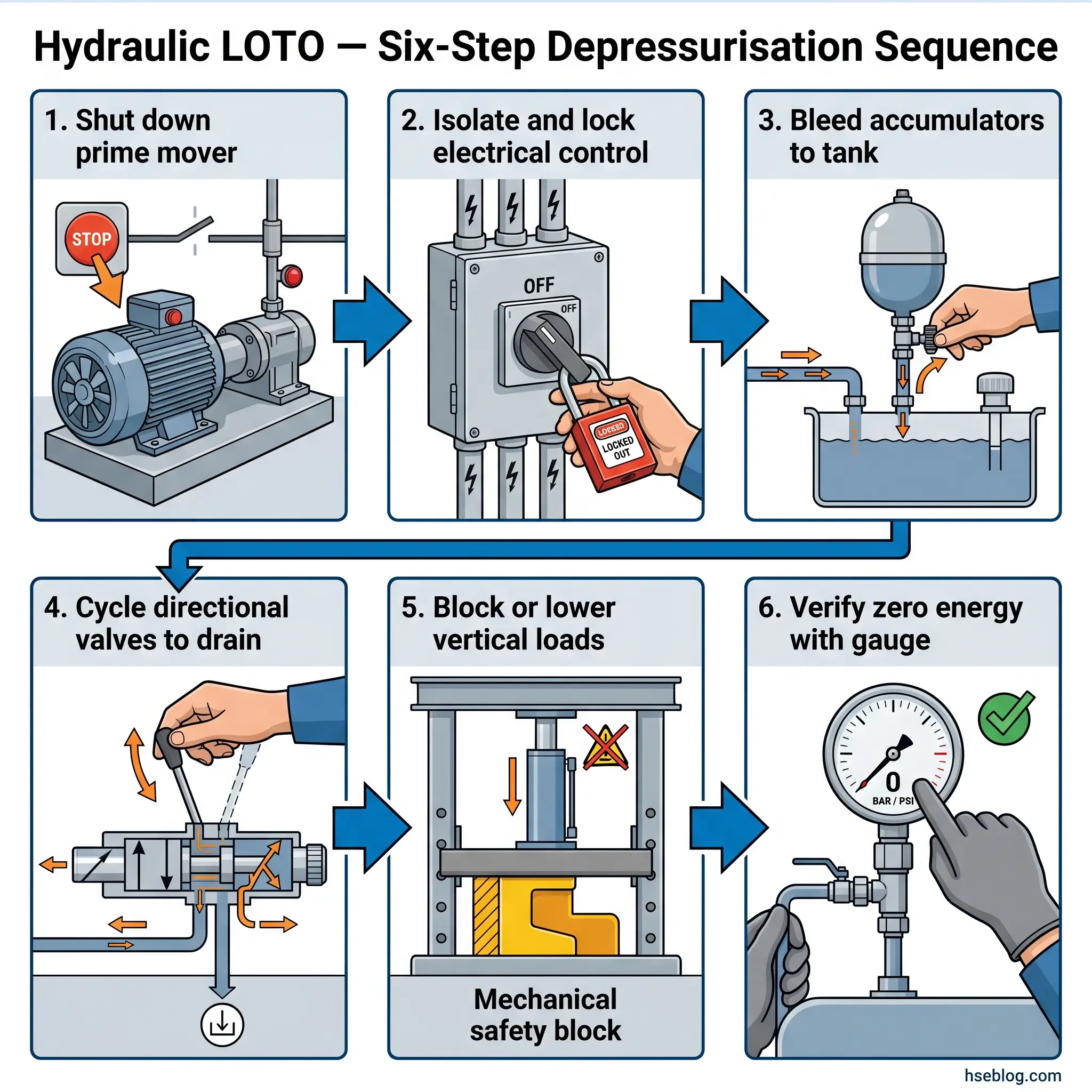
Reading these together, hydraulic lockout is not a switch flip. It is a sequence:
- Shut down the prime mover. The pump stops adding pressure. The system is not yet safe.
- Isolate electrical control. Lock out the motor or engine starter so the pump cannot restart.
- Bleed accumulators on both sides. The hydraulic side is bled to tank through the accumulator’s bleed valve. The gas (nitrogen) side is checked, and if servicing involves accumulator disassembly, the gas charge is also released — never simultaneously, never without verification.
- Cycle the directional control valves. Manual override or hand-pump cycling drains pressure trapped between closed valves — the hidden charge that holds even after the pump is locked out.
- Lower or block vertical loads. Cylinders holding loads against gravity must be lowered to a mechanical rest, or blocked by stands, before any line is opened. Hydraulic locking does not survive servicing.
- Verify with a gauge. A pressure reading at the system’s working point is the verification step. Not the pump status. Not the operator’s recollection. The gauge.
The leak-detection method belongs in this section because it intersects with daily hydraulic safety. Never use a hand or finger to find a leak. The published method is to run a piece of cardboard, plywood, or plexiglass slowly along the suspected line, watching for fluid spray or staining on the test material. Stand to the side of the suspected leak, not in front of it.
The Fix That Works Procedures that survive shift pressure are the ones that list each accumulator and its bleed valve explicitly, by ID number. Generic “bleed all stored energy” language does not survive a fast turnaround. Named locations do.
PPE for hydraulic work is layered. Face shield over safety glasses. Long sleeves of cut- and chemical-resistant material. Oil-resistant gloves. The workers who deserve the clearest communication on this are the ones most likely to overestimate it: PPE protects against incidental fluid contact and burn exposure. It does not stop a high-pressure jet. The control that prevents injection injury is the procedure, not the equipment.
Hydraulic Hose Selection, Inspection, and Replacement
Hose assemblies are the single most-replaced wear item in a hydraulic system and the leading source of injection-injury incidents. ISO/TS 17165-2:2018 sets the global reference for selection, fabrication, installation, and replacement of hydraulic hose assemblies, and Annex A of that document lists the actual failures observed when its guidance is not followed. The selection framework most field technicians work to is STAMPED — Size, Temperature, Application, Material, Pressure, Ends, Delivery — six dimensions that determine whether a hose will survive its service life.
A working observation across maintenance literature: roughly 80% of hose failures trace to external physical damage rather than internal pressure fatigue. Abrasion against adjacent equipment, kinking from poor routing, crushing from foot traffic or dropped tools, and twisting during installation cause more failures than overpressure. That has a direct implication for inspection: routing and protection are at least as important as the hose itself. A hose that lasts ten years on a clean routing fails in eighteen months when it rubs against a steel beam.
Replacement triggers that override calendar intervals:
- Cover cracking, hardening, or blistering. The reinforcement underneath has begun to fatigue.
- Exposed reinforcement wire. Replace immediately — there is no remaining safety margin.
- Kinks, twists, or sharp bends below minimum bend radius. Bend-radius violations damage the reinforcement permanently.
- Oil seepage at fittings or along the cover. A pinhole has already started.
- Manufacture date approaching SAE-cited service life. SAE references rubber-hose service life of approximately ten years from manufacture; many manufacturers recommend earlier replacement under high-cycle or harsh-environment service.
- Compatibility mismatch with the fluid in use. Pressure rating must exceed system maximum including pressure spikes, and the hose must be rated for the fluid type.
Hoses are replaced, not repaired. A hose with a damaged fitting is a new hose. The pattern that bites most operations is reactive single-hose replacement: a hose fails in service, it gets replaced, and the hoses routed alongside it — manufactured at the same time, exposed to the same heat, vibration, and abrasion — are left in place until they fail in turn. The maintenance discipline that separates well-run programmes is hose-set replacement on bays rather than single hoses.
Hydraulic Accumulator Safety
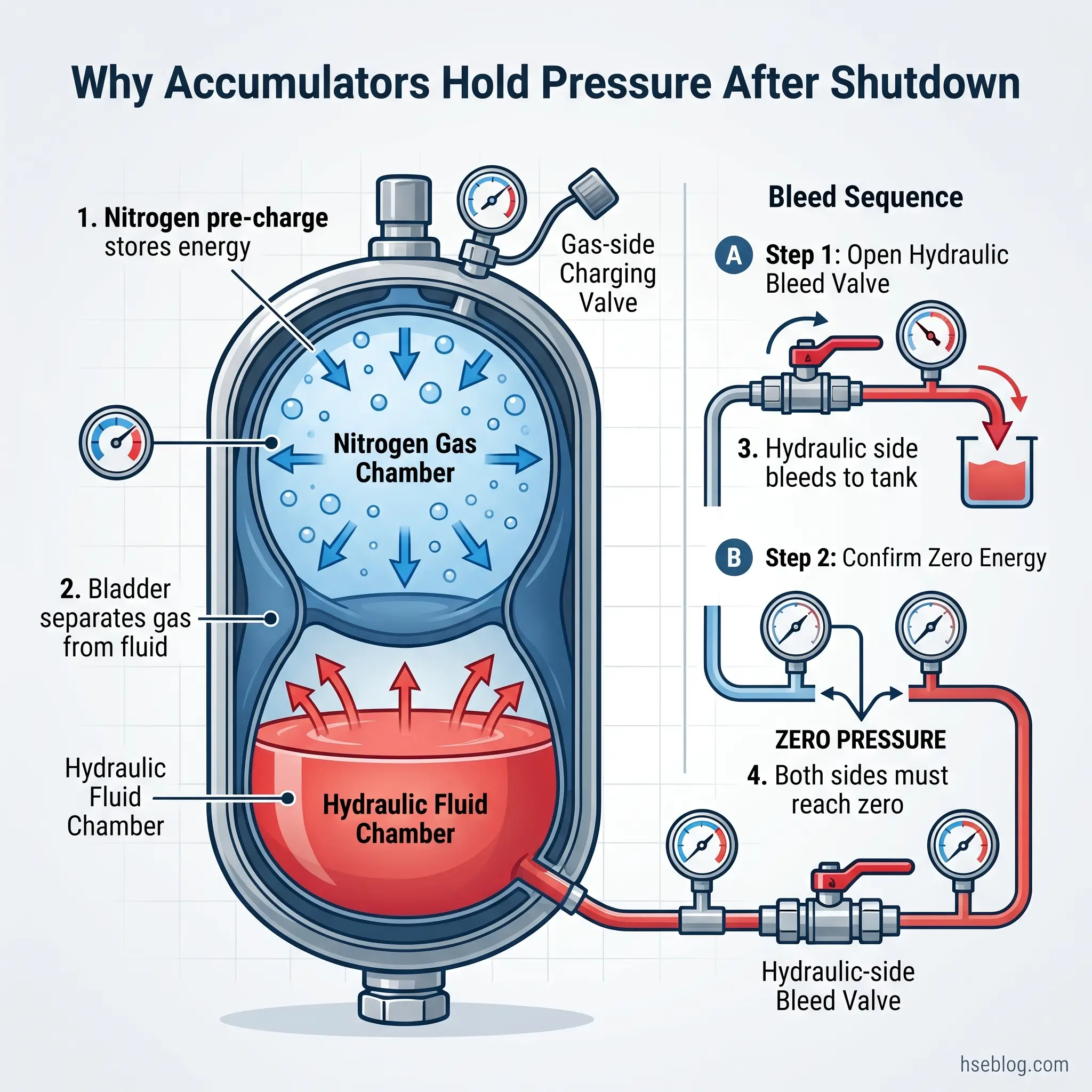
Accumulators deserve their own section because they are the single most omitted energy source in hydraulic LOTO procedures and the source of multiple documented fatalities. Their entire design purpose is to store hydraulic energy and release it on demand — which is precisely the property that makes them dangerous to service.
Pre-charge maintenance is the foundation. Accumulators are typically pre-charged to 80–90% of minimum working pressure, and the charge gas must be nitrogen — never compressed air. Compressed air introduces oxygen into a vessel containing hydraulic oil and creates conditions for an explosive mixture under pressure. Pre-charge is verified every 6–12 months per manufacturer instruction, and the verification is part of the planned-maintenance schedule, not the response to a fault.
The depressurisation sequence for an accumulator under service has its own ordering:
- Isolate the accumulator from the system using the manufacturer-specified isolation valve.
- Open the hydraulic-side bleed valve to direct stored fluid pressure to tank. Verify zero pressure on the hydraulic-side gauge.
- If the accumulator is to be disassembled, release the gas-side pre-charge through the gas valve. Use the correct gas-charging tool — never improvised hardware.
- Confirm both sides are at zero before any port is opened.
- After service, recharge the gas side to the manufacturer-specified pre-charge using nitrogen only.
Audit Point A LOTO procedure that does not name each accumulator by location and identify its bleed valves — gas-side and hydraulic-side, separately — is a procedure that has never been executed on the worst day. Walk the procedure against the equipment. If the procedure cannot be executed by someone unfamiliar with the system, it is not a procedure.
Fluid Management and Contamination Control
Contamination is the failure category every other failure category eventually traces back to. Four contaminant types matter: solid particulate, water, air, and the heat-degradation byproducts that fluid generates as it ages. Each enters the system through a different route and damages it through a different mechanism.
Particulate enters through worn rod seals, breather caps that have lost their filter element, top-up containers that were left open on a dusty floor, and during maintenance work where the system is opened without contamination control. Water enters through condensation in reservoirs subject to thermal cycling, through failed seals on outdoor equipment, and through ingress during washdown. Air contamination has two distinct forms: dissolved air, which is the precursor to cavitation, and entrained air, which is the visible foam of aeration. Heat-degradation byproducts — oxidised fluid, varnish, polymerised additive residues — accumulate over time and progressively foul valve clearances and cooler surfaces.
The control framework is layered. ISO 4406 cleanliness codes are the standard reference for specifying and verifying fluid cleanliness; they describe particle count by size at three levels (≥4 µm, ≥6 µm, ≥14 µm), and most OEMs specify a cleanliness target the system must maintain. Filter management is condition-based, not calendar-based — replace per OEM hours or per differential pressure indicator, whichever comes first. Periodic fluid analysis using particle counting, water content (Karl Fischer), and viscosity testing identifies degradation before it causes a failure. The sampling cadence depends on system criticality; typical intervals run from monthly on critical systems to quarterly on routine industrial use.
The interpretation that most matters in field practice: “we changed the oil” is not the same as “we removed the contamination.” A system with varnish on its internal surfaces will recontaminate fresh fluid within days. Where varnish is suspected, a flushing protocol — using compatible flushing fluid at controlled velocity and temperature — is the only path to clean restart. Skipping the flush and changing the fluid is the most common reason a “fluid change” doesn’t fix the problem.
Regulatory and Standards Framework Across Jurisdictions
The standards landscape divides cleanly by jurisdiction, with the substantive provisions converging on a similar set of principles. Sites cited under OSHA 29 CFR 1910.147 typically show the same procedural gap — failure to address stored hydraulic energy during servicing — and the standard’s position as the third-most-cited federal standard in FY2024 (US Occupational Safety and Health Administration, 2024) reflects how persistent that gap is across US industry. ISO 4413:2010 is the controlling design-side reference globally; in the UK and EU it has been adopted as BS EN ISO 4413, and HSE Guidance Note GS4 references it directly for pressure-testing safety. ISO/TS 17165-2:2018 governs hose-assembly practice worldwide. PUWER 1998 in Great Britain extends the reach to maintenance, isolation, and inspection in a way that reads more like a duty than a specification.
The forward-compliance item every export-facing operation needs to have on its programme is EU Machinery Regulation 2023/1230. Published 14 June 2023, the regulation becomes binding on 20 January 2027 and replaces Machinery Directive 2006/42/EC (European Commission, 2023). Its expansion of essential health and safety requirements covers digital control systems, cybersecurity, AI-based safety functions, and updated documentation provisions — relevant to hydraulic systems integrating IoT-based predictive maintenance, condition monitoring, or remote diagnostics. A 2025 review of Industry 4.0 to 5.0 transitions in fluid power notes that pressure, vibration, and ultrasonic sensors integrated with condition-monitoring platforms have moved from research deployment to mainstream industrial use, which is exactly the technical territory the new regulation governs.
| Jurisdiction | Standard | Key requirement |
|---|---|---|
| US | OSHA 29 CFR 1910.147 | Stored-energy isolation including hydraulic, with verification on reaccumulation |
| UK | PUWER 1998, Reg. 11 & 19; HSE GS4 | Equipment safety, isolation, and pressure-test guidance |
| Global | ISO 4413:2010; ISO/TS 17165-2:2018 | Hydraulic system design safety; hose-assembly practice |
| EU (from 20 Jan 2027) | Regulation (EU) 2023/1230 | Machinery safety with cybersecurity and AI provisions |
Jurisdiction Note Procedures written to OSHA compliance alone often pass US inspections but fail audit when the same equipment is exported or operated by an international client expecting ISO conformity. Writing procedures to ISO 4413 plus OSHA 1910.147 covers both domains with a single document set — and pre-positions the operation for EU 2023/1230 enforcement.
The conflicting-standards principle here is straightforward: where requirements overlap procedurally — as they do for stored-energy release — apply the stricter procedural step. Where requirements diverge by domain — design (ISO 4413), operation (OSHA 1910.147, PUWER 1998), pressure testing (HSE GS4), market access (EU 2023/1230) — apply each within its scope.
Legal disclaimer: Regulatory content here reflects general HSE professional understanding of the jurisdictions named, current as of 2025–2026. It is not legal advice. Specific compliance questions, enforcement situations, or prosecution risk should be directed to qualified legal counsel in the applicable jurisdiction.
Building a Hydraulic Safety Programme: The Practical Layer
A hydraulic safety programme that survives audit and prevents injury is built around equipment-specific document sets, not generic plant-wide procedures. The single highest-leverage observation across well-run programmes: each piece of hydraulic equipment has its own written energy-control procedure that names accumulators by ID, names vertical cylinders by location, names isolated line segments by tag number, and references the bleed valves by drawing reference. Generic procedures fail at the worst moment because they cannot be executed without site knowledge that may not be present.
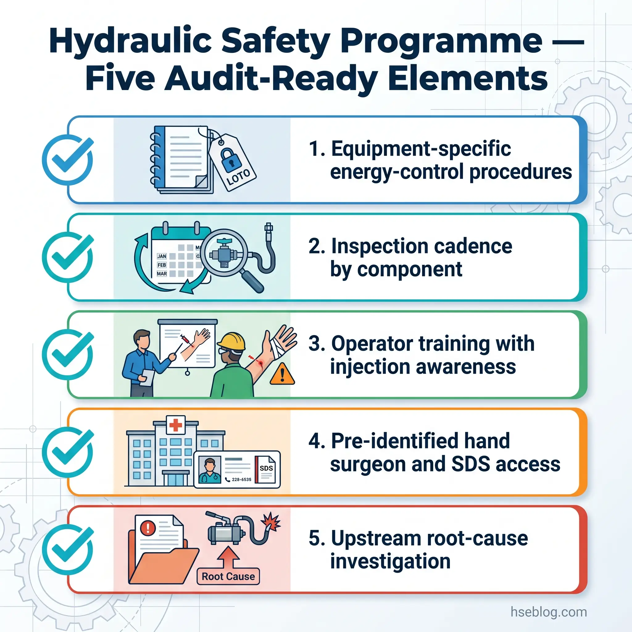
The five elements that show up consistently in programmes that prevent injury:
- Equipment-specific written energy-control procedures naming every accumulator, vertical cylinder, and isolated line segment, with ID numbers and drawing references.
- Inspection schedule with component-specific cadence: hose visual checks daily on high-cycle equipment, formal hose inspection per ISO/TS 17165-2 guidance, fluid analysis monthly to quarterly, accumulator pre-charge verification every 6–12 months, filter replacement on differential pressure or OEM hours.
- Operator training that includes injection-injury awareness, the cardboard leak-detection method, and the emergency-response sequence — including what the worker tells emergency staff.
- Medical response plan: pre-identified hand surgeon, briefing of the receiving hospital on injection-injury protocol before an incident occurs, fluid SDS sheets accessible at the work area not buried in a binder.
- Incident investigation that always traces upstream: a pump failure investigation that ends at “the pump failed” is a programme failure. The investigation continues into the suction line, the filter, the fluid, and the procedural conditions until the actual originating cause is identified.
Condition-monitoring and predictive-maintenance integration is the layer that emerging programmes are now adding — pressure transducers, vibration sensors, ultrasonic leak detection, and inline particle counters integrated with site control systems. The value of this layer depends on system criticality and on whether the data feeds into a maintenance decision the operation will actually act on. Sensors that generate alerts no one investigates are a programme weakness, not a strength.
Frequently Asked Questions
Conclusion
The operational discipline of hydraulic system safety reduces to a small number of decisions made consistently. Treat every active system as capable of injection injury, regardless of how its pressure rating compares with the visible activity. Treat the pump shutdown as the start of depressurisation, not the end of it — accumulators, vertical cylinders, and isolated lines hold pressure independently and must each be addressed before service. Treat hose replacement as set-replacement, not single-component replacement, because the hoses adjacent to the failure share its history.
Build the programme around equipment-specific document sets that name each pressure-retaining component by ID. Anchor the operational procedures to OSHA 29 CFR 1910.147 in the US, PUWER 1998 in the UK, and ISO 4413:2010 globally — and pre-position for EU Machinery Regulation 2023/1230 if any equipment will be operated within or exported to the EU after 20 January 2027. Run fluid management as cleanliness control rather than scheduled fluid changes; the contamination is what damages the system, not the calendar.
The control that most distinguishes high-performing programmes from average ones is the medical handoff. The injection injury that defines hydraulic system safety as an elevated-risk discipline cannot be wholly prevented — pinhole leaks happen, fittings fail, charged lines are encountered without warning. What can be controlled is what happens in the next two hours. A pre-identified hand surgeon, a fluid SDS at the workstation, a worker trained to say high-pressure injection injury to emergency staff rather than cut or puncture — those are the elements that change outcomes, and they are the elements competitor pages on this topic consistently omit.