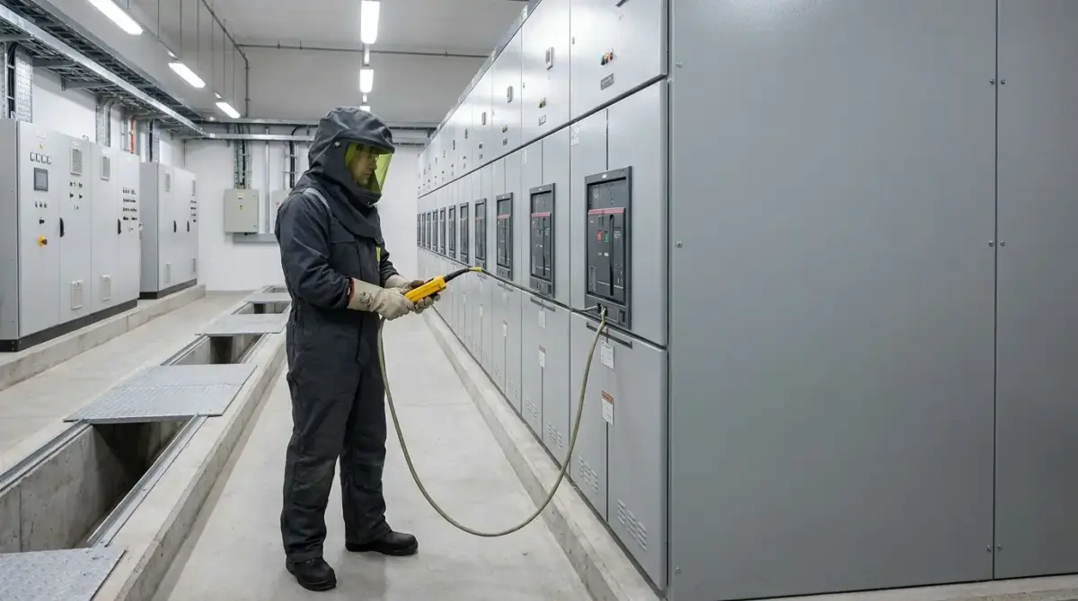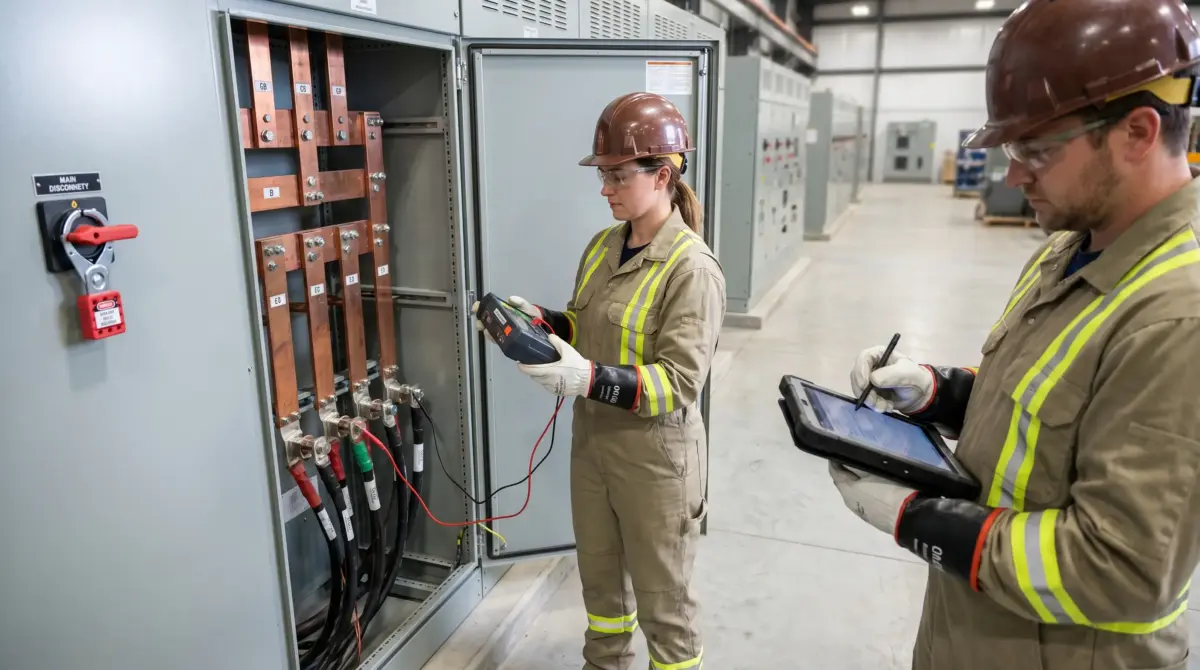
Insulation resistance testing is a non-destructive diagnostic procedure that applies a controlled DC voltage across electrical insulation and measures the resulting leakage current to quantify insulation quality. It detects degradation from moisture, contamination, thermal aging, or mechanical damage before it leads to equipment failure, electric shock, or fire. The test is performed using a megohmmeter and is one of the most fundamental tools in any electrical preventive maintenance program.
In 2023 and 2024 combined, 5,180 non-fatal electrical injuries involving days away from work were reported in the United States alone — a 59% increase over the prior two-year period (Electrical Safety Foundation International, 2026, compiled from U.S. Bureau of Labor Statistics data). Behind many of these injuries is a failure mechanism that develops silently over months or years: insulation breakdown. When the protective barrier between energized conductors and ground degrades past a critical point, the result is leakage current, short circuits, arc flash, or fire — often with no external warning until the moment of failure.
Insulation resistance testing exists to catch that degradation early. It is the simplest, most repeatable diagnostic available for assessing the condition of electrical insulation in cables, motors, transformers, switchgear, and wiring installations. This article covers the measurement principle behind the test, the different test types available and when each one is the right choice, the step-by-step procedure, test voltage selection across jurisdictions, result interpretation including trending and temperature correction, and the critical safety requirements that protect the person holding the instrument.
This article provides general HSE knowledge. Life-critical work such as insulation resistance testing on energized or recently de-energized systems must be planned and supervised by a competent person with relevant training, jurisdiction-specific authorization, and site-specific risk assessment. The information here does not replace that.
What Is Insulation Resistance Testing and Why Does It Matter?
Insulation resistance testing quantifies how effectively the insulation barrier between energized conductors — and between conductors and earth — resists current flow. The test applies a known DC voltage across the insulation and measures the small current that leaks through it. The ratio of applied voltage to leakage current gives the insulation resistance in megohms. A high reading indicates the insulation is intact; a declining reading over time indicates it is failing.
The principle is straightforward, but the diagnostic value depends on understanding what happens electrically during the test. Three distinct currents flow when the test voltage is applied: capacitive (charging) current, which surges initially as the insulation's capacitance charges and decays within seconds; absorption (polarization) current, caused by molecular alignment within the dielectric material, which decays much more slowly over minutes; and leakage (conduction) current, the steady-state current that flows through and across the insulation and represents the true measure of insulation quality. Every advanced test method — polarization index, dielectric absorption ratio, step voltage — depends on distinguishing these three components.
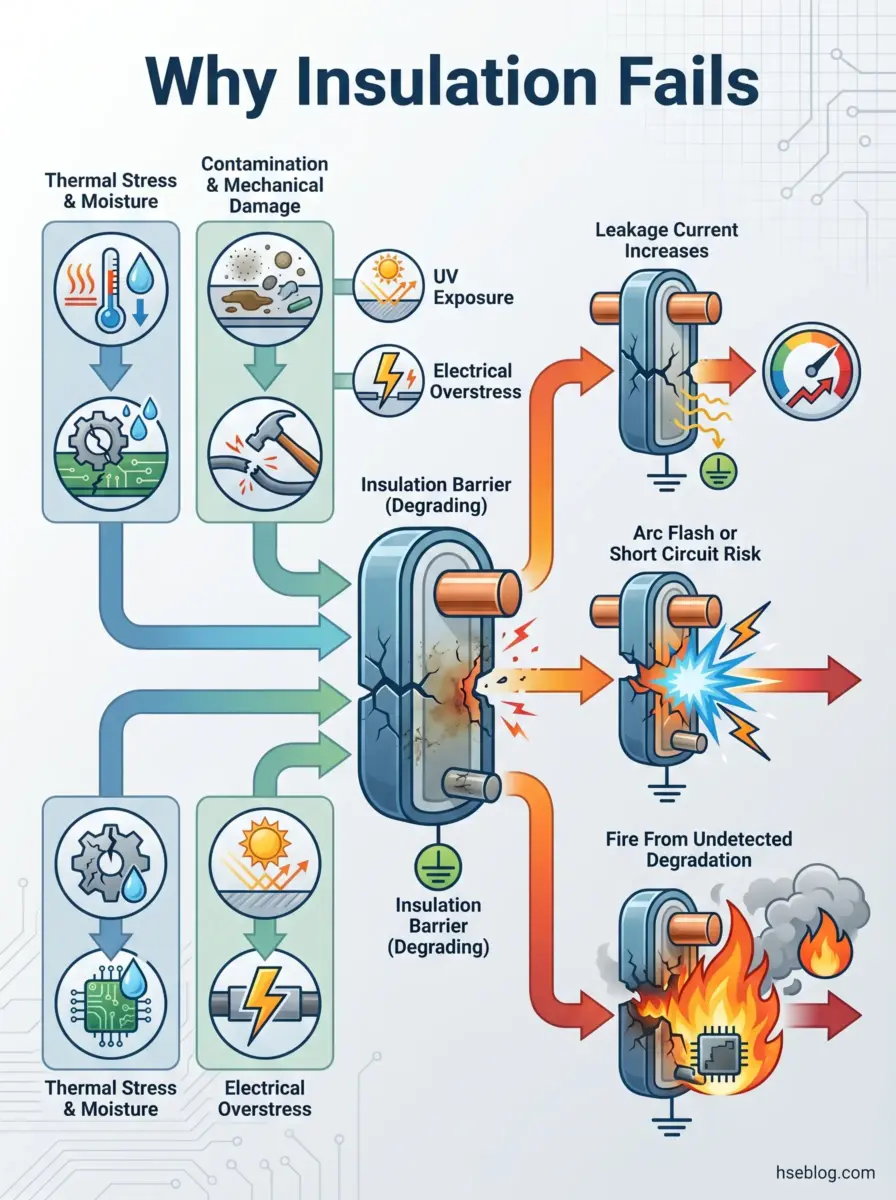
Insulation begins degrading from the moment of installation. Thermal cycling, moisture ingress, chemical contamination, mechanical vibration, UV exposure, and electrical overstress all contribute. Over 50,000 electrical system fires occur annually in the United States, resulting in approximately $1.3 billion in property damage (ESFI/NFPA fire data, 2025). Insulation degradation is a contributing factor in a significant proportion of these failures. The value of IR testing is not in any single pass/fail reading — it is in recording and trending results over time against a baseline, revealing degradation curves that predict failure months before it occurs.
How Insulation Resistance Testing Works: The Measurement Principle
A megohmmeter — commonly called a megger — generates a stable DC voltage and applies it across the insulation under test. The instrument measures the resulting current and calculates resistance. DC voltage is used rather than AC because AC would continuously charge and discharge the insulation's capacitance, masking the leakage current that reveals actual insulation condition.
The behaviour of the three current components over time explains why test duration matters. Capacitive current is the largest component initially but decays to near-zero within the first 10–15 seconds on small equipment. Absorption current decays much more gradually, typically requiring 5–10 minutes to stabilize. Leakage current remains essentially constant throughout the test — it is the component that reflects the true condition of the insulation. The standard 1-minute spot reading exists as a practical compromise: long enough for capacitive current to decay, short enough for routine field use.
A common diagnostic error occurs on large motors or long cable runs, where capacitive current can remain significant well beyond 15 seconds. A technician who reads at 30 seconds on a 500-metre cable run may record a misleadingly low value and flag serviceable insulation for replacement. Understanding the time-decay curve — and recognizing when equipment size demands a longer reading window — separates competent testing from mechanical button-pressing.
Modern megohmmeters range from hand-crank models generating 500 V DC to battery-powered instruments capable of 5 kV or higher, with automatic PI and DAR calculation, temperature correction, and data logging. The instrument itself must comply with IEC 61557-2 (International, 2019), which specifies accuracy, output voltage stability, and performance requirements to ensure measurement traceability.
Types of Insulation Resistance Tests: Choosing the Right Method
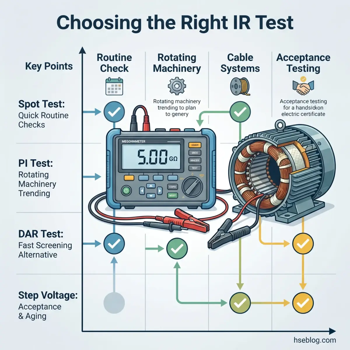
Most competing guidance on this topic lists test types without helping the reader decide which one to use. The decision depends on three factors: what equipment is being tested, what question needs answering, and how much time is available.
| Test Type | Duration | Best For | Key Metric | Primary Limitation |
|---|---|---|---|---|
| Spot Reading | 60 seconds | Routine checks, low-capacitance equipment | Megohm value at 1 min | Affected by temperature and humidity; no trend data alone |
| Time-Resistance | 1–10 minutes | Medium/large motors, cables | Resistance curve shape | Requires interpretation skill |
| Polarization Index (PI) | 10 minutes | Rotating machinery, stator windings | 10-min / 1-min ratio | Requires full 10 minutes; impractical for quick checks |
| Dielectric Absorption Ratio (DAR) | 60 seconds | Quick screening where PI is impractical | 60-s / 30-s ratio | Less diagnostic resolution than PI |
| Step Voltage | Variable | Acceptance testing, age-related damage | Resistance consistency across voltages | Requires multi-voltage instrument |
Spot Reading (Short-Time) Test
The spot reading applies test voltage for 60 seconds and records the result. It is the most common field test and serves as a quick go/no-go assessment. Its limitation is that the absolute megohm value depends heavily on ambient temperature and humidity, making direct comparison between readings taken under different conditions unreliable without correction.
Time-Resistance (Timed) Test
Readings taken at intervals during a single test — typically at 30 seconds, 1 minute, and 10 minutes — produce a resistance-versus-time curve. Clean, dry insulation shows a steadily rising curve as absorption current decays. Contaminated or wet insulation produces a flat curve because leakage current dominates from the start. The advantage of this method is that the curve shape is largely independent of equipment size, making results comparable across different motors or cable lengths.
Polarization Index (PI) Test
The polarization index is the ratio of the 10-minute reading to the 1-minute reading. IEEE 43 (US/International, 2000) recommends a minimum PI of 2.0 for rotating machinery insulation. A PI close to 1.0 indicates the absorption current is not decaying — the insulation is severely contaminated or wet. Because PI is a ratio, it is effectively temperature-independent, making it more reliable than absolute megohm values for trending rotating machinery over time.
Audit Point: When reviewing maintenance records for rotating machinery, check that PI values are being recorded — not just spot readings. A spot reading of 500 MΩ with a PI of 1.2 is far more concerning than a spot reading of 50 MΩ with a PI of 4.0.
Dielectric Absorption Ratio (DAR) Test
DAR is the ratio of the 60-second reading to the 30-second reading. A DAR of 1.4 or higher generally indicates acceptable insulation condition. It provides a faster alternative to the full PI test when a 10-minute window is unavailable, though it offers less diagnostic resolution.
Step Voltage Test
The step voltage test applies progressively increasing voltages — for example, 500 V DC followed by 1,000 V and then 2,500 V. Sound insulation maintains consistent resistance regardless of applied voltage. A drop in resistance at higher voltage reveals internal cracks, voids, or contamination invisible to low-voltage tests. This test is particularly valuable for detecting age-related mechanical damage in insulation that appears clean and dry.
The step voltage test is the most underused method in the field. Many modern instruments support it, but technicians default to spot readings because they have not been trained on step voltage interpretation. For acceptance testing of new high-value rotating machinery, step voltage testing should be standard practice — it catches manufacturing defects that a single-voltage spot test cannot reveal.
Step-by-Step Insulation Resistance Test Procedure
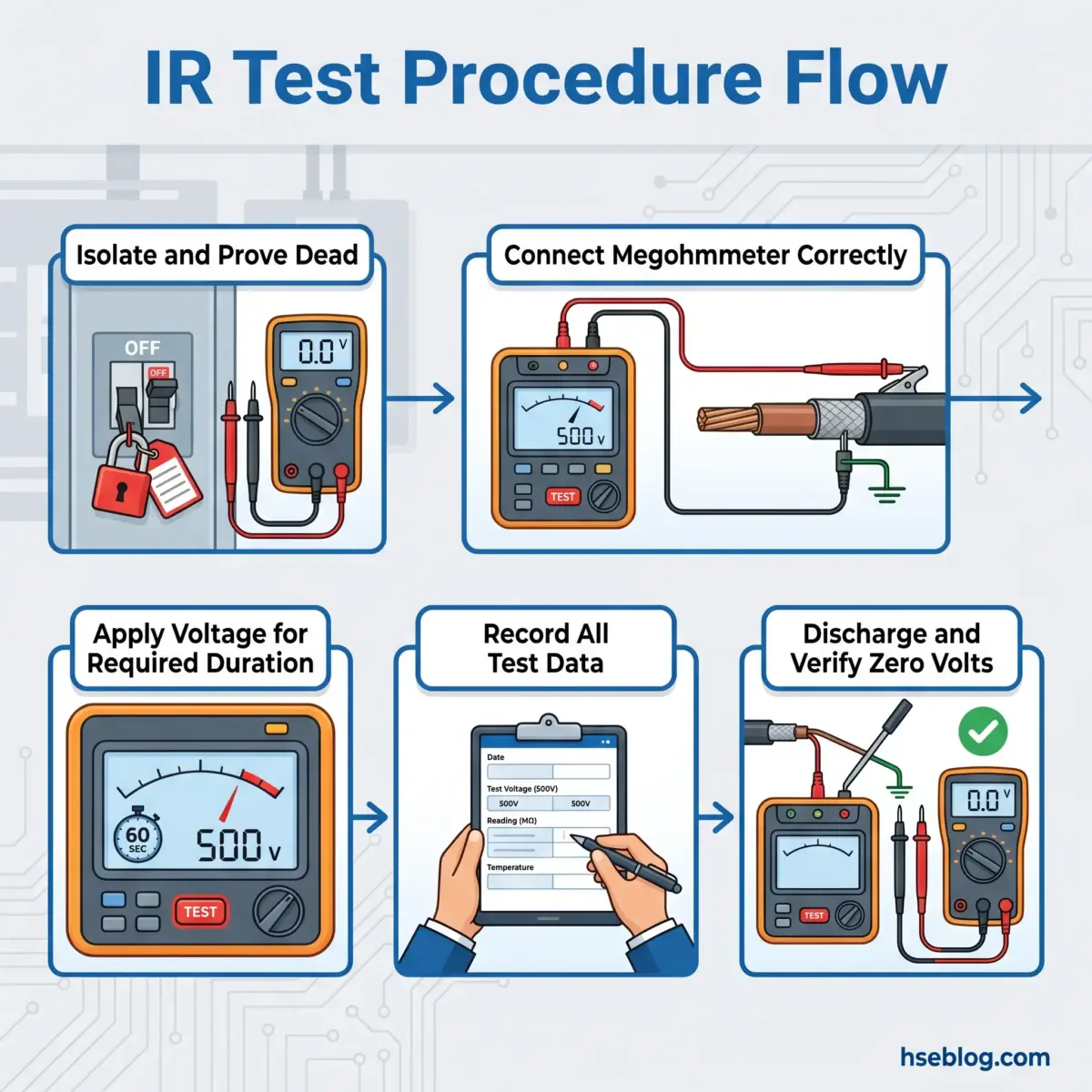
The following procedure assumes the tester is a competent person with appropriate training and authorization. Each step matters — particularly the discharge sequence, where the most serious injuries tend to occur.
- Review equipment documentation. Identify the test points, confirm the equipment's rated voltage, and determine the correct test voltage. Check the manufacturer's maintenance manual for any specific IR testing instructions or restrictions.
- Assess ambient conditions. Record the ambient temperature and relative humidity before testing. These values are essential for temperature-correcting the results later. If humidity is above 80% or condensation is visible, surface moisture may produce misleadingly low readings — consider deferring the test or drying the equipment first.
- De-energize and isolate. Follow the site's lockout/tagout procedure to de-energize the circuit under test. In the US, this falls under OSHA 29 CFR 1910.147. Under BS 7671 (UK, 2022), the safe isolation procedure requires proving the circuit dead with an approved voltage indicator that has been verified immediately before and after use.
- Prove dead. Use an approved voltage indicator — not the megohmmeter — to confirm the circuit is de-energized. Verify the indicator functions correctly on a known live source before and after the test.
- Disconnect sensitive components. Remove or disconnect surge protective devices, electronic controls, capacitors, indicator lamps, and any equipment that may be damaged by the test voltage or that could influence readings.
- Connect the megohmmeter. Attach the LINE terminal to the conductor under test and the EARTH terminal to the ground or protective conductor. Where surface leakage must be excluded from the measurement — such as on multi-conductor cables or bushing insulation — connect the GUARD terminal to divert surface currents away from the measurement circuit.
- Restrict access. Ensure no other personnel can contact the circuit under test. The megohmmeter applies potentially hazardous DC voltages — up to 5 kV on some instruments.
- Apply the test voltage. Select the correct voltage for the equipment class and engage the test. For a spot reading, maintain the voltage for 60 seconds. For a PI test, maintain for 10 minutes. Allow readings to stabilize before recording.
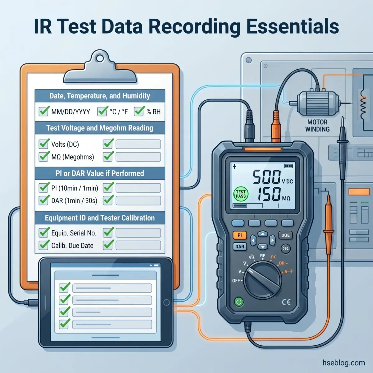
- Record the result. Document the test voltage applied, the megohm reading, the time of reading, the ambient temperature and humidity, the equipment identification, and the tester's calibration status.
- Discharge stored energy. This is critical. Large cable runs and motor windings store significant capacitive charge at the applied test voltage. Maintain the megohmmeter connections and allow the instrument's discharge function to operate. The minimum discharge time is four times the test duration for highly capacitive loads — but this is a floor, not a target. Verify zero voltage with a voltmeter before disconnecting any leads or touching any conductors.
- Restore the circuit. Reconnect any components removed in Step 5. Remove lockout/tagout devices following the site procedure. Return the circuit to service.
Watch For: The discharge step is where the most serious injuries happen during IR testing. A 1,000-metre cable run tested at 5 kV can retain a charge capable of delivering a painful — and potentially fatal at height — shock. Never assume the charge has dissipated. Measure. Verify. Then touch.
How to Select the Correct Test Voltage
Test voltage selection is one of the most common sources of error in insulation resistance testing. The general principle is that the DC test voltage should approximate the circuit's AC operating voltage, rounded to the nearest standard instrument setting — but the specific requirements vary by standard and equipment category.
| Circuit Nominal Voltage | Test Voltage (IEC 60364) | Test Voltage (BS 7671) | Minimum IR Value |
|---|---|---|---|
| SELV/PELV (up to 50 V) | 250 V DC | 250 V DC | 0.5 MΩ |
| Up to 500 V (including 230/400 V) | 500 V DC | 500 V DC | 1 MΩ |
| Above 500 V | 1,000 V DC | 1,000 V DC | 1 MΩ |
These values come from IEC 60364-6, Clause 6.4.3.3, Table 6.1 (International, 2016) and BS 7671:2018+A2:2022, Regulation 643.3 and Table 64 (UK, 2022). Amendment 2 of BS 7671 introduced a significant procedural change: all installed conductors must first be tested at the full Table 64 voltage before equipment is connected, with a subsequent 250 V DC test after connection. This two-stage approach was not required under previous editions and changes how electricians must sequence initial verification on UK installations.
For rotating machinery, IEEE 43 (US/International, 2000) specifies higher test voltages based on winding voltage class. Machines rated below 1,000 V are tested at 500 V DC. Machines rated 1,001–2,500 V are tested at 500–1,000 V DC. Machines rated 2,501–5,000 V are tested at 1,000–2,500 V DC. Higher-rated machines scale accordingly, with test voltages up to 10,000 V DC for windings rated above 12,000 V. The IEEE 43 recommended practice for rotating machinery provides the complete voltage class table.
A recurring misconception is that 500 V DC is a universal default. On SELV circuits rated at 12 V or 24 V, applying 500 V DC is excessive and risks damaging sensitive components — the correct test voltage is 250 V DC. On medium-voltage cable systems, 500 V DC may be too low to reveal defects that only manifest at voltages closer to the operating level. The test voltage must always match both the equipment class and the purpose of the test.
Jurisdiction Note: Sites operating under BS 7671 must now comply with the Amendment 2 two-stage test requirement for initial verification. IEC 60364 does not mandate this two-stage approach, and US practice under NFPA 70B does not specify it. Electricians working across jurisdictions should confirm which testing sequence applies before starting.
Interpreting Insulation Resistance Test Results
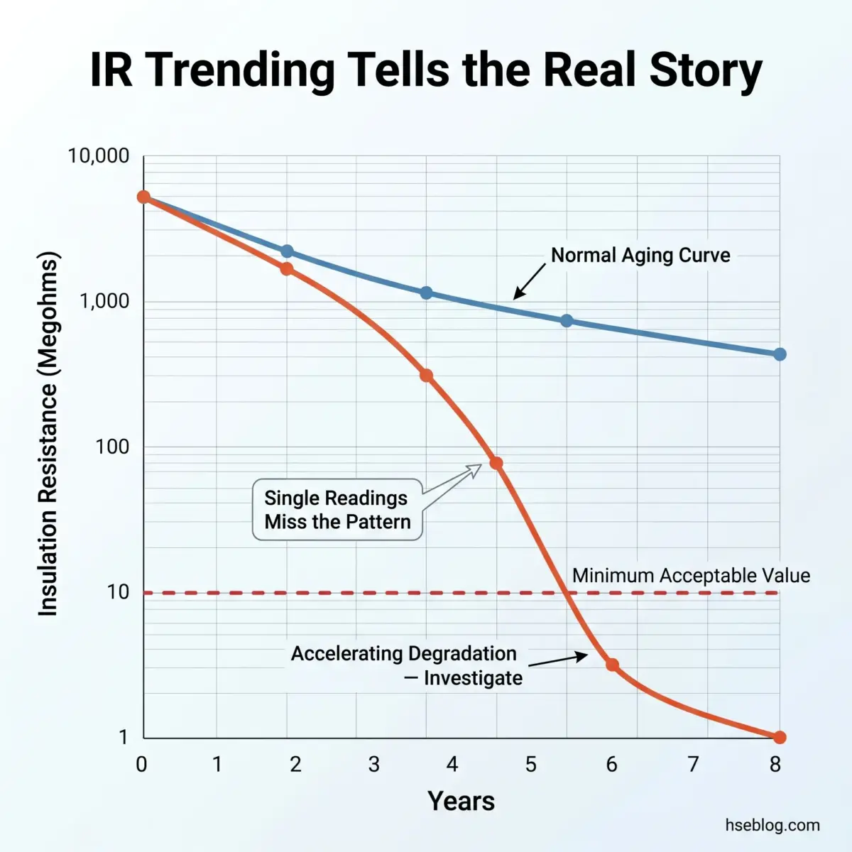
A reading above the minimum threshold means the insulation has not failed. It does not mean the insulation is healthy. The diagnostic power of insulation resistance testing lies entirely in the trend.
Minimum Acceptable Values
The widely cited rule of thumb — 1 MΩ per kV of operating voltage, with a 1 MΩ floor — serves as a general-purpose benchmark for low-voltage installations. IEC 60364-6 (International, 2016) sets specific minimums: 1 MΩ for circuits up to 500 V tested at 500 V DC, and 0.5 MΩ for SELV/PELV circuits tested at 250 V DC. IEEE 43 uses the formula IR₁ = kV + 1 (megohms, at 40°C) for rotating machinery rated below 10,000 kVA — so a 4.16 kV motor must show at least 5.16 MΩ.
Temperature Correction
Insulation resistance approximately halves for every 10°C rise in temperature. A motor winding tested at 60°C will show roughly one-quarter the resistance of the same winding tested at 40°C — both readings may represent identical insulation condition. Readings must be normalized to a reference temperature for any comparison to be valid.
This is where a critical inconsistency across the literature creates confusion. IEEE 43 specifies 40°C as the standard reference temperature for rotating machinery. Some manufacturer literature — including from Megger — references 20°C. The choice of reference temperature does not matter as long as it is consistent within the trending record for each piece of equipment. Mixing reference temperatures across readings makes the trend meaningless.
Humidity Effects
Readings taken in high-humidity conditions can be misleadingly low due to surface moisture on insulation rather than actual internal degradation. If humidity exceeds 80%, or condensation is visible, the reading reflects surface conditions more than bulk insulation quality. The IET guidance on insulation resistance testing under BS 7671 notes this as a common cause of unnecessary investigation on installations tested during winter mornings in unheated buildings.
Trending Over Time
An initial commissioning reading of 5,000 MΩ that drops to 50 MΩ over two years is far more alarming than a stable reading of 10 MΩ held consistently over the same period. The shape of the degradation curve matters more than any single absolute value. Plotting temperature-corrected readings against time reveals whether insulation is aging normally (gradual, predictable decline) or developing an active fault (accelerating decline).
What Is the Difference Between Insulation Resistance Testing and Hipot Testing?
This is one of the most common points of confusion in electrical testing, and conflating the two leads to either under-testing or — worse — over-testing that accelerates insulation failure.
| Feature | Insulation Resistance (IR) Test | Hipot (Dielectric Withstand) Test |
|---|---|---|
| Purpose | Diagnostic — quantify insulation quality | Proof — verify insulation can survive overvoltage |
| Voltage Level | Moderate DC (250 V – 5 kV, matching equipment class) | High (typically 2× rated + 1,000 V AC, or DC equivalent) |
| Destructive? | No — non-destructive at correct voltage | Potentially — stresses insulation to near-breakdown |
| Repeatable? | Yes — trend-friendly, designed for periodic use | Limited — excessive repetition degrades insulation |
| Typical Use | Preventive maintenance, periodic inspection | Acceptance testing, post-repair verification |
| What It Reveals | Insulation quality, degradation trends, contamination | Whether insulation can withstand transient overvoltages |
| Key Standard | IEC 60364, IEEE 43, BS 7671 | IEC 60060, IEEE 95, manufacturer specifications |
A component can pass an IR test and fail a hipot test. This happens when internal voids or delamination exist that allow current to flow only at voltages well above the operating level — the IR test's moderate voltage does not reach the breakdown threshold, but the hipot's elevated voltage does.
In maintenance contexts, insulation resistance testing is the workhorse. Hipot testing is reserved for acceptance of new equipment, post-repair verification, or specific periodic requirements. Routinely applying hipot voltages to aging equipment is counterproductive — each application stresses the insulation and may itself initiate the failure it was meant to detect.
Safety Precautions for Insulation Resistance Testing
The output current of a megohmmeter is typically limited to a few milliamps and is not in itself lethal under normal conditions. The real hazards are the stored capacitive energy in the equipment under test and the startle reaction — a minor shock at height can cause a fatal fall.
NFPA 70E:2024 (US, 2024) defines the qualified person requirements for personnel performing electrical testing, including IR tests. Under BS 7671 Regulation 134.1.1 (UK, 2022), only a skilled person or instructed person under appropriate supervision may carry out insulation resistance testing. Both frameworks require the tester to understand the electrical hazards, the test equipment, and the isolation procedure — not merely to operate the instrument.
Full lockout/tagout must be completed before any IR test begins. OSHA lockout/tagout citations surged 29% from 2022 to 2023, rising from 1,968 to 2,532 citations (Grace Technologies, 2024 State of Electrical Safety Report, compiled from OSHA data). This persistent violation rate suggests that the procedural discipline required for safe electrical testing is still not embedded in many organizations.
PPE requirements for IR testing include insulated gloves rated for at least the test voltage, safety glasses, and arc-rated clothing where arc flash risk exists during isolation or restoration. Environmental factors compound the risk: wet conditions reduce the body's contact resistance, metallic floors create low-impedance fault paths, and elevated work positions turn a startle reaction into a fall hazard. IR testing must never be performed in explosive atmospheres unless the instrument carries a valid certification for the applicable hazardous zone classification.
The Fix That Works: Treat every IR test as a three-phase job: isolate, test, discharge. The middle phase gets all the attention in training — but injuries cluster in the first phase (inadequate isolation) and the third (inadequate discharge). Build the discharge verification into the test procedure as a mandatory sign-off step, not an afterthought.
Insulation Resistance Testing in Preventive Maintenance Programs
NFPA 70B transitioned from a recommended practice to a mandatory standard in the 2023 edition. Insulation resistance testing is now explicitly listed among the required condition-based maintenance field test methods under Chapter 8 (US, 2023). This is not a semantic change — it elevates IR testing from a "best practice" suggestion to an enforceable requirement within the jurisdictions that adopt the standard. The next edition, expected in 2026, has received nearly 4,000 public inputs, signalling further evolution of these requirements.
Under NFPA 70B Chapter 9, testing frequency should be determined by a condition-based assessment that considers the equipment's physical condition, operational criticality, and environmental exposure. The standard provides intervals ranging from 12 to 60 months depending on the assessment outcome. Manufacturer guidelines, where more stringent, take precedence.
The single most impactful action for any preventive maintenance program is capturing baseline IR readings at commissioning. Without a reference point, future readings lack diagnostic context. A technician confronted with a reading of 20 MΩ on a 400 V motor has no way to determine whether that represents stable, healthy insulation or the endpoint of a steep decline — unless a commissioning baseline exists. Equipment installed without a baseline IR reading can never be properly trended, forcing reliance on absolute thresholds that catch failures only after they become severe.
Data management is equally critical. Each test record should include the date, ambient temperature and humidity, test voltage applied, megohm reading, PI or DAR value if performed, equipment identification, and the tester's serial number and calibration status. Cloud-connected instruments and trending software reduce transcription errors and enable automated degradation alerts — but the discipline of recording complete data on every test is the foundation, regardless of the technology used.
Frequently Asked Questions
What is the minimum acceptable insulation resistance value?
The minimum depends on the applicable standard and equipment type. IEC 60364-6 (International, 2016) requires 1 MΩ for circuits up to 500 V and 0.5 MΩ for SELV/PELV circuits. For rotating machinery, IEEE 43 (US/International, 2000) uses the formula kV + 1 in megohms at 40°C for machines below 10,000 kVA. The widely cited rule of 1 MΩ per kV of operating voltage with a 1 MΩ floor is a general benchmark, not a universal standard. Always verify the applicable standard for the specific installation.
Can a multimeter be used for insulation resistance testing?
No. Standard multimeters cannot generate the sustained high DC voltage — 250 V to 5,000 V — required for insulation resistance measurement. Their resistance function applies only a few volts, which is insufficient to stress the insulation enough to reveal degradation. A dedicated megohmmeter compliant with IEC 61557-2 (International, 2019) is required. Using a multimeter gives unreliable readings and satisfies no recognized testing standard.
Why does insulation resistance decrease with temperature?
Higher temperatures increase molecular activity within insulating materials, creating additional pathways for leakage current to flow. The relationship is approximately logarithmic — resistance roughly halves for each 10°C increase. A reading of 100 MΩ at 20°C and 25 MΩ at 40°C may represent the same insulation condition. All readings must be corrected to a standard reference temperature — 40°C per IEEE 43, or 20°C per some manufacturer references — for valid trending.
What causes a low insulation resistance reading?
Common causes include moisture ingress, surface or bulk contamination from dust, oil, or chemicals, physical damage to the insulation from vibration or mechanical impact, thermal aging from prolonged overheating, and electrical overstress from transient overvoltages. Moisture and surface contamination are often reversible through cleaning and drying. Thermal aging and mechanical damage indicate permanent insulation deterioration that typically requires rewinding or replacement.
What does a polarization index below 2.0 mean?
Per IEEE 43 (US/International, 2000), a PI below 2.0 suggests the insulation is contaminated with moisture or conductive material. The absorption current is not decaying normally, indicating that leakage current dominates the measurement from the start. A PI approaching 1.0 signals severe compromise. Before condemning the equipment, clean and thoroughly dry the insulation and re-test — if the PI recovers, the cause was environmental contamination rather than irreversible damage.
What is the guard terminal on a megohmmeter and when should it be used?
The guard terminal provides a separate current path that diverts surface leakage current around the measurement circuit, so the instrument reads only the volume resistance of the insulation. Use it when testing multi-conductor cables where leakage between conductors and along insulation surfaces would distort the reading, or when testing bushing insulation where surface contamination is present. Without the guard, surface currents are included in the measurement, producing an artificially low reading that does not reflect the actual condition of the insulation bulk.
Conclusion
The persistent gap in insulation resistance testing across the industry is not the absence of testing — it is the absence of context around the readings. Technicians test, record a number, compare it against a minimum threshold, and move on. The reading passes, the box is ticked, and the equipment returns to service. What gets missed is the trajectory: whether that reading is stable, declining gradually, or in accelerating freefall toward failure. A single reading is a snapshot. A trended, temperature-corrected series of readings is a diagnostic tool that predicts failures months in advance.
The highest-impact change most maintenance programs can make is not buying better instruments or testing more frequently. It is capturing baseline readings at commissioning, recording complete environmental data with every subsequent test, and plotting corrected results over time. That discipline transforms insulation resistance testing from a compliance checkbox into the early-warning system it was designed to be.
NFPA 70B's 2023 transition from recommended practice to mandatory standard reflects the broader recognition that condition-based maintenance — with IR testing as one of its core methods — is no longer optional for responsible electrical asset management. The organizations that get this right will be the ones whose equipment fails predictably and manageably, rather than catastrophically and without warning.
Regulatory content in this article reflects general HSE professional understanding of the cited jurisdictional requirements as of 2025. It is not legal advice. Specific compliance questions, enforcement situations, or prosecution risk should be directed to qualified legal counsel in the applicable jurisdiction.