
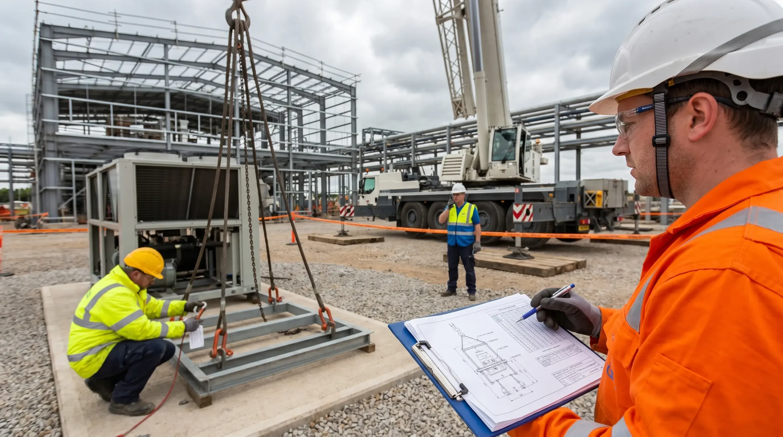
Regulation 8 of LOLER puts it in twenty-seven words: every lifting operation involving lifting equipment shall be properly planned by a competent person, appropriately supervised, and carried out in a safe manner. On paper that sounds administrative. On a live EPC site at 06:30 with two crawlers booming up, a 38-tonne steam turbine module on skids, and a shift superintendent asking whether you are ready, that clause is the difference between a controlled pick and a prosecution file. The inspector who audited us last quarter opened with exactly that: “Show me the plan, the calculations, and the signatures.” Nothing else.
A lifting plan is the single document that holds all of that together — the load data, the crane capacity, the ground bearing, the rigging, the sequence, the stop-work triggers, the names of every person with their hands on a tag line. This article is the writing guide I wish I had when I first qualified as an Appointed Person. It covers what a lifting plan actually is in legal and operational terms, when one is required, the twelve elements every written plan should contain, the step-by-step reasoning used to produce it, a worked example, and the mistakes that still show up in accident reports today.
What Is a Lifting Plan?
A lifting plan is a documented, risk-proportionate set of instructions that describes how a specific lifting operation will be carried out safely. It defines the load, the lifting equipment, the accessories, the personnel, the environment, the sequence of work, and the controls in place if something changes mid-lift. It is not a generic safety document — it is the written safe system of work for one lift or one class of lifts, and it exists to translate regulatory duty into a procedure that a crew can actually follow.
The scope is wider than most people assume. Mobile cranes and tower cranes obviously need one. So do overhead cranes, gantry cranes, forklifts, telehandlers used for lifting, hoists, winches, excavators rigged for lifting duty, and mobile elevating work platforms carrying loads. Under UK law, any equipment used for lifting loads or people falls within LOLER, and planning under Regulation 8 applies to all of it. The depth of the plan scales — a pallet move in a warehouse needs a generic templated document and a toolbox talk; a 140-tonne reactor vessel tandem lift over a live pipe rack needs an engineered plan, a PE stamp, and a client sign-off before the crane rolls onto site.
It is useful to separate the plan from the permit. A permit-to-lift is the short-duration authorisation issued on the day; the lifting plan is the longer-form technical document the permit references. The permit says “you are authorised to execute Plan LP-247 today, weather window 07:00–11:00.” The plan says exactly what LP-247 is.
A lifting plan has three jobs: satisfy the regulator, control the operation, and brief the team. Any plan that does only one of the three is a plan on its way to an incident report.
Why a Lifting Plan Matters: The Risk Case
Cranes kill. Not often in relative terms, but consistently. The US Bureau of Labor Statistics recorded 297 deaths involving cranes in the 2011–2017 window, and an earlier NIOSH review of 632 construction crane fatalities between 1992 and 2006 averaged out to roughly 42 deaths per year. Those are the lifts the plan was supposed to catch.
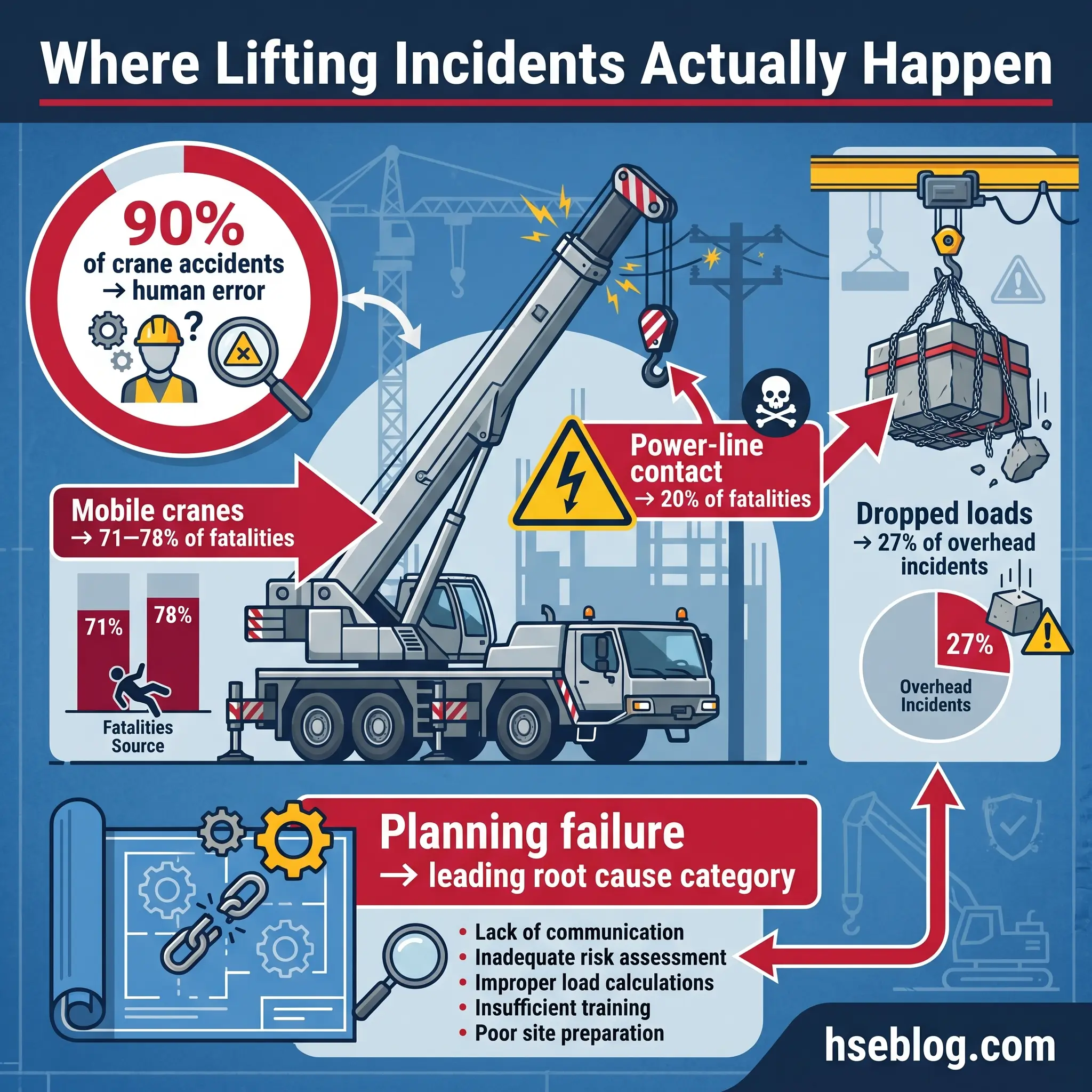
The more important number is behavioural. Crane Inspection & Certification Bureau analysis puts approximately 90% of crane accidents down to human error rather than equipment failure — and the largest controllable subset of that is planning failure: wrong load weight, wrong radius, wrong ground, wrong people. A crane that passes inspection can still overturn if the Appointed Person got the ground bearing pressure wrong.
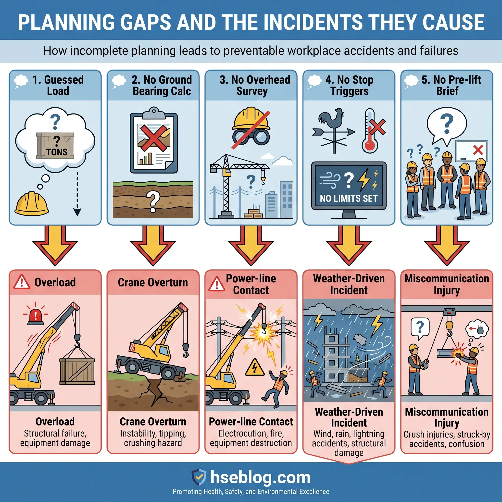
The incident patterns a written plan is specifically built to prevent are not subtle:
- Power-line contact, which accounts for roughly 20% of construction crane fatalities and around 100 crane/power-line contact events per year in the US — planning failure dressed up as operator error.
- Rigging failure and dropped loads, which one industry review of 249 overhead crane incidents found involved dropped loads in 27% of cases.
- Ground failure under outriggers from lifts executed without a ground bearing calculation.
- Overload, almost always tied to guessed load weights or ignored hook-block weight.
Mobile and truck-mounted cranes absorb most of this: NIOSH data shows roughly 71–78% of fatal crane incidents involve mobile cranes, with tower cranes around 5%, overhead/gantry around 12%, and floating/barge 3–4%. The profile matters because it tells you where planning discipline has to be sharpest — and on a mobile crane lift, the plan is doing the heavy lifting long before the hook does.
Beyond human cost there is a commercial one. A prosecution under LOLER carries unlimited fines in UK Crown Courts. An OSHA willful violation is five figures per instance. A failed lift on a critical path module can put an EPC project weeks behind and trigger liquidated damages that dwarf the crane contract. The plan is cheap insurance against all of it.
When Is a Lifting Plan Legally Required?
Short answer: always. Longer answer depends on your jurisdiction, because the trigger for a written plan varies.
Under UK law, LOLER Regulation 8 requires every lifting operation to be planned by a competent person — no threshold, no exception. The Approved Code of Practice L113 fleshes this out with twelve planning factors covering load, equipment, environment, personnel, proximity hazards, and continuing integrity of the equipment during the lift. For routine lifts, the plan can be generic and cover a class of operations; for non-routine lifts, a specific written plan is expected.
In the United States, OSHA 29 CFR 1926.1417 sets operation requirements including verification of load weight, and 1926.751 defines a critical lift as one exceeding 75% of rated capacity or requiring more than one crane. Where two or more cranes share a load, 29 CFR 1926.1432 mandates a written plan prepared by a qualified person and a pre-lift meeting reviewed with everyone involved.
For engineered and critical lifts, the consensus technical standard is ASME P30.1-2019 Planning for Load Handling Activities, backed by ASME B30.5 for mobile cranes and B30.26 for rigging hardware. Internationally, ISO 12480-1 provides the safe-use baseline and is the standard I reference when a project spans multiple regulatory regimes. European member states work to the same intent through EU Directive 2009/104/EC on work equipment, transposed into each country’s law.
| Jurisdiction | Trigger for written plan | Who must prepare it | Primary source |
|---|---|---|---|
| UK | Every lifting operation (depth proportional to risk) | Appointed Person (competent) | LOLER 1998, Reg 8 + ACoP L113 |
| US | Critical lift: >75% rated capacity or multi-crane | Qualified Person / Lift Director | 29 CFR 1926.1417, .1432, .751 |
| International | Engineered / complex lifts | Qualified / competent person | ISO 12480-1; ASME P30.1-2019 |
| EU member states | All work equipment use | Competent person | Directive 2009/104/EC + national law |
The practical test I give trainees is simpler than any of the above: if something went wrong, would you be comfortable handing this plan to an investigator? If the answer is no, the plan is not finished.
Types of Lifts and the Level of Plan Each Needs
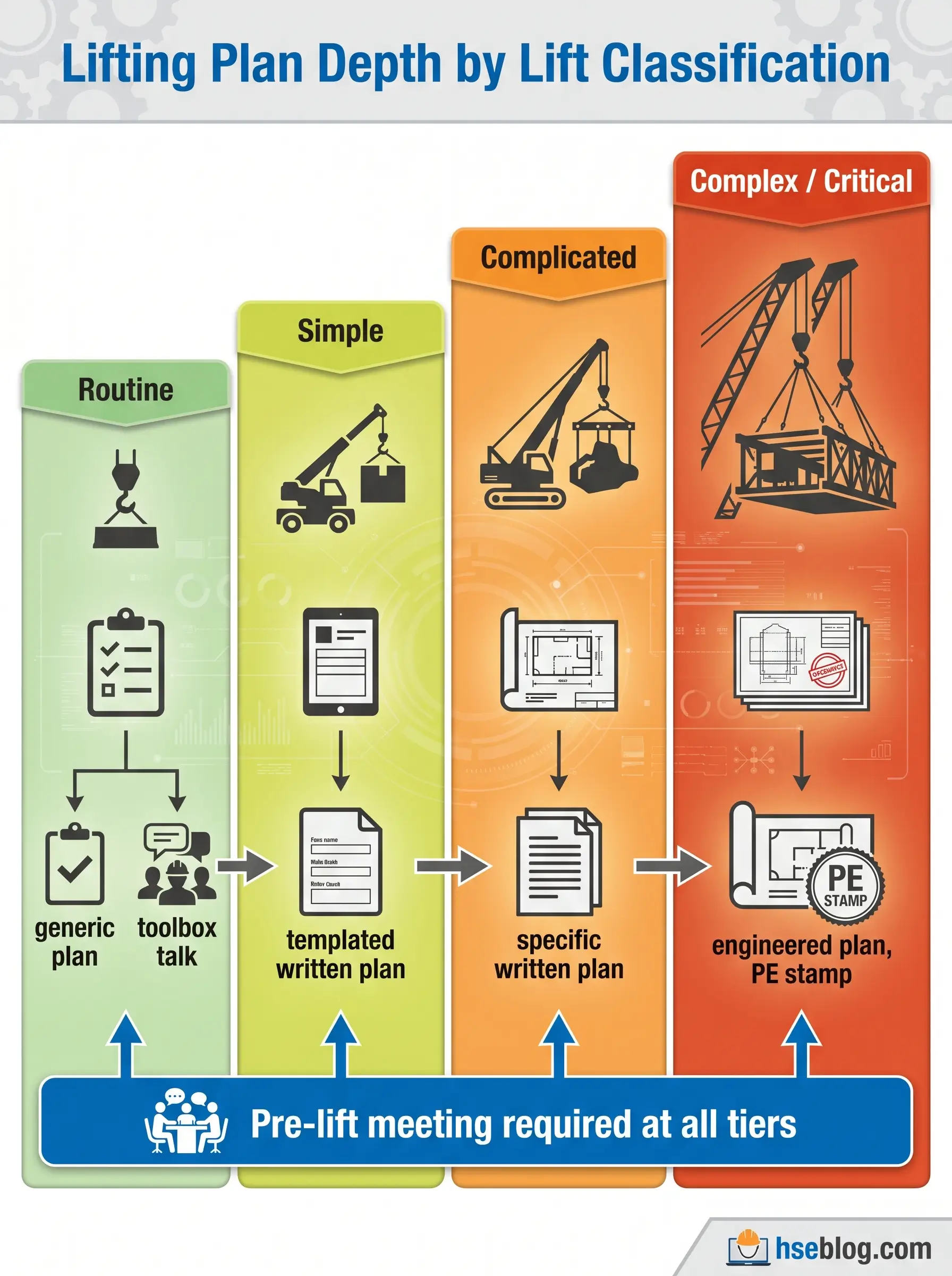
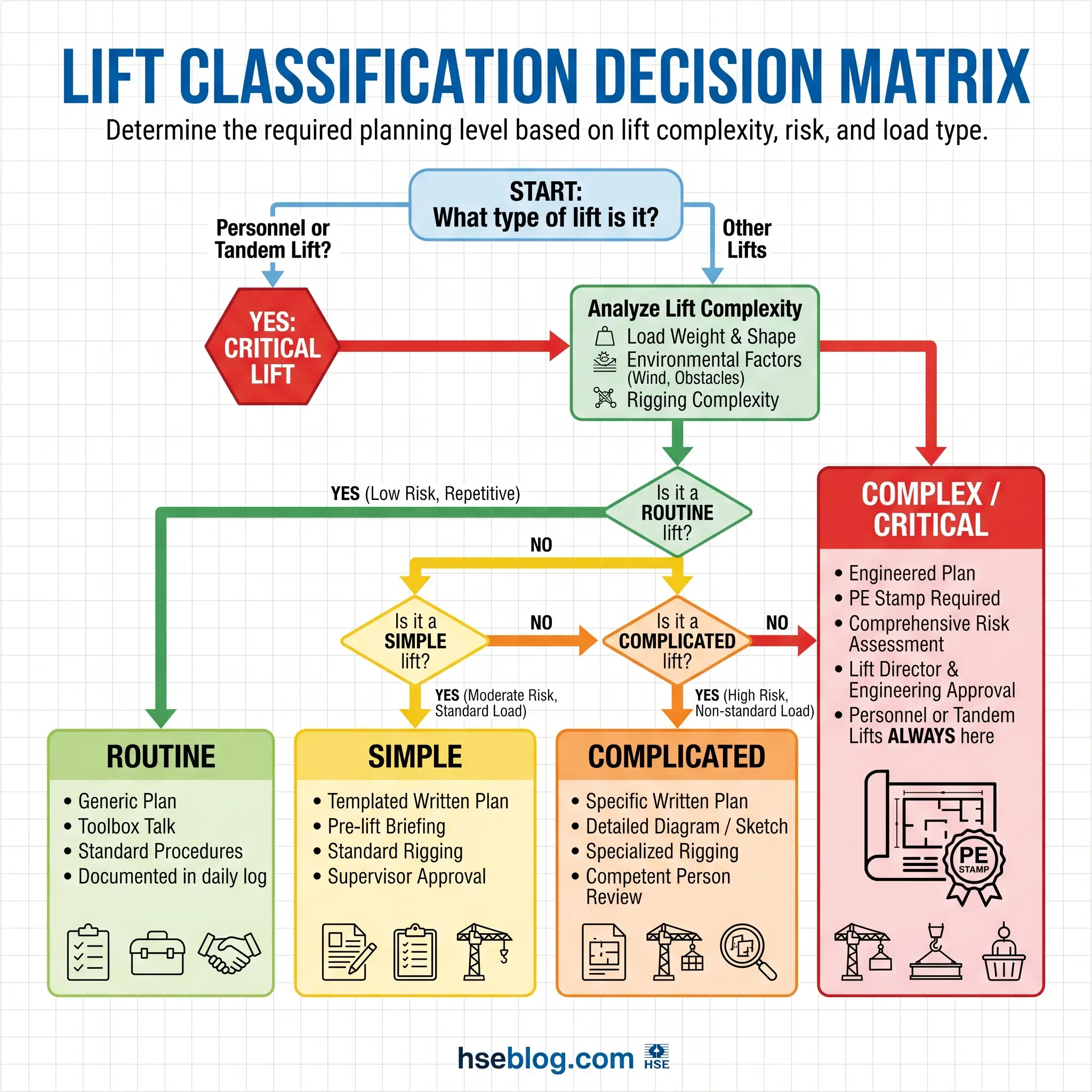
The four-tier classification used widely in offshore, EPC and heavy construction gives you the planning depth in one decision. Pin down the category first; everything else follows.
Routine lifts are repetitive operations with a known, stable load, a proven configuration, and a familiar environment — pallet moves in a yard, forklift deliveries to a laydown, deck moves on an offshore platform. A generic lifting plan plus a documented risk assessment and a toolbox talk covers these. The plan is written once and applies to the class of operations.
Simple or standard lifts are single-crane lifts with a known load, stable ground, no awkward rigging, and no proximity hazards. A templated written plan filled in for the specific job — crane model, radius, load, rigging — is sufficient. Most module set-downs in a laydown area fall here.
Complicated lifts break at least one of the “standard” conditions — non-routine load shape, awkward centre of gravity, multi-step sequence, tight swing clearance, work over active walkways. A specific written plan is required, with lift diagrams, calculated ground bearing pressure, and a pre-lift meeting. Most turbine-hall interior lifts I handle fall in this tier.
Complex, critical or engineered lifts require the full treatment: detailed engineering, formal calculations, a PE stamp where required, third-party review, and often client witness. The triggers:
- Load exceeds 75% of rated chart capacity at the planned radius (OSHA; NIOSH recommends treating 70–90% as critical).
- Tandem lift — two or more cranes sharing a load.
- Personnel lifting (man-basket, work over occupied areas below).
- Release of hazardous material if the load falls (ASME/Hanford consequence criterion).
- Exceptionally high-value or schedule-critical payload.
- Configuration at or above 90% of the load chart anywhere in the lift envelope.
What Makes a Lift “Critical”?
The OSHA line — 75% of rated capacity or multi-crane — is the hard legal threshold in the US, but it is a minimum. NIOSH and most EPC contractors I work with treat anything between 70% and 90% of chart as a critical lift and apply the full engineered-lift discipline: qualified-person preparation, lift director present, documented trial lift, and third-party review of calculations. ASME P30.1 adds consequence-based triggers that matter more than percentage: if a dropped load would release a hazardous substance, endanger personnel below, or disable a high-value asset, the lift is critical regardless of capacity utilisation. I have seen a 22% capacity lift classified critical because the load was a containment valve assembly over a live process line. Percentages are a starting point; consequence is the real test.
Who Prepares the Lifting Plan? Roles and Competence
Responsibility confusion is itself a root cause. The answer to “who owns this plan” should never require a meeting — it should be written on the cover sheet.
The Appointed Person is the UK title defined under BS 7121 and reinforced by ISO 23813. The AP owns the plan, selects the crane, calculates the lift, and has the authority to stop the job. The equivalent US role under OSHA 1926.1432 is the Lift Director or qualified person for the engineered-lift aspects. Below those, the Lift Supervisor runs the operation on the day. The crane operator executes within the plan’s envelope. Slingers/riggers attach the load. The signaller or banksman communicates with the operator. Each role has stop-work authority for their scope.
Competence is the word the law uses and the word sites most often get wrong. A ticket — CPCS A61 Appointed Person, NPORS AP, NCCCO, LEEA — demonstrates training. Experience demonstrates judgement. Authority to stop the job demonstrates empowerment. A plan signed by someone with the ticket but no experience of that class of lift is a plan waiting to fail. I have watched an AP with three years of mobile-crane work correctly refuse to sign a tandem lift plan on the grounds he had never led one; the project pushed back, and he held. That was the right call.
| Role | Core duty | Typical qualification | Stop-work authority |
|---|---|---|---|
| Appointed Person / Lift Director | Overall planning, crane/rigging selection, approval | CPCS A61, NPORS AP, qualified person designation | Yes — unlimited |
| Lift Supervisor | Execute plan, brief team, hold weather limits | CPCS A62, site experience | Yes — operational |
| Crane Operator | Safe operation within plan envelope | CPCS, NCCCO, NPORS operator | Yes — for equipment/load |
| Slinger / Rigger | Attach load, verify WLL of accessories | CPCS A40, LEEA training | Yes — for rigging |
| Signaller / Banksman | Communicate with operator | CPCS A64, NCCCO signalperson | Yes — for signals lost |
The Essential Elements of a Lifting Plan
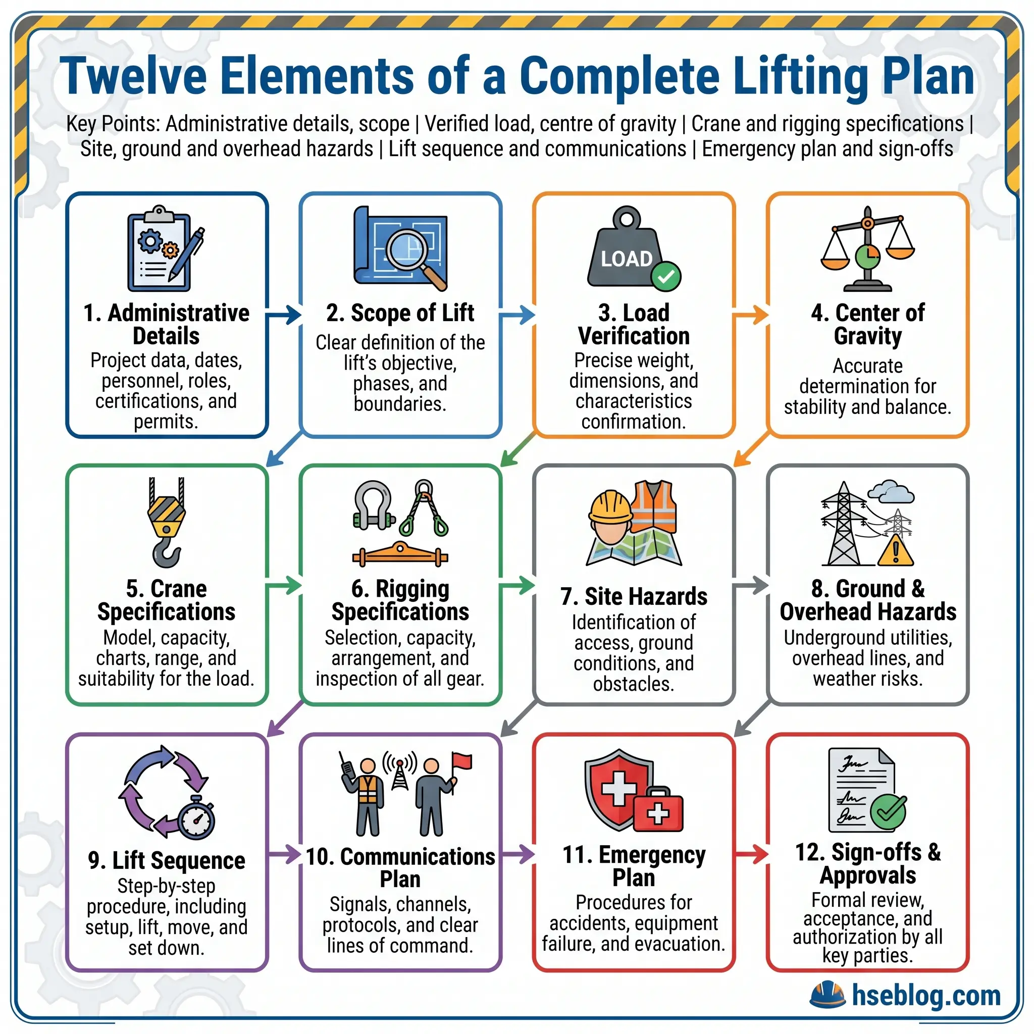
A written plan should contain, at minimum, the components below. Each element exists because removing it has caused incidents. Group them as you write — administrative, load, equipment, site, execution, approvals.
Administrative and scope
- Plan reference: unique number, revision, date, next review date.
- Project and client details: site, contract, client representative.
- Named personnel: Appointed Person, Lift Supervisor, operator, slingers, signallers — with qualifications and ticket expiry dates.
- Scope of work: a one-paragraph description of what is being lifted, from where, to where, and why.
Load data
- Verified weight: from data sheet, nameplate, weigh cell or calculation — never from a superintendent’s memory. A 4-tonne “guess” that turns out to be 5.2 tonnes is a 30% overload the operator cannot see.
- Dimensions and centre of gravity: critical for sling selection and balance.
- Lifting points: design lugs, trunnions, slinging positions — with the WLL of each.
- Hazardous contents or characteristics: pressurised, hot, radioactive, environmentally sensitive.
Lifting equipment and accessories
- Crane: make, model, serial, capacity, boom length and configuration, counterweight, inspection and thorough examination certificates with expiry.
- Accessories: slings (type, length, WLL at chosen angle), shackles, spreader beam/frame with WLL, below-the-hook devices with certificates. The hook block and headache ball weights must be captured here — they are part of the gross load.
Site and environmental conditions
- Crane position: with outrigger spread and pad size.
- Ground bearing capacity: calculated required versus available under each outrigger or track.
- Overhead hazards: power lines, pipe racks, structures — with minimum approach distances.
- Underground hazards: cables, drains, voids, buried services — confirmed by scan, not assumption.
- Weather limits: maximum wind speed (typically 9.8 m/s for most mobile operations, lower for large wind-area loads), visibility, temperature, lightning triggers.
- Access, egress and exclusion zones.
Execution
- Lift sequence / method statement: step by step, referencing the diagram.
- Communication method: dedicated radio channel, hand signals, blind-lift provisions if operator cannot see load or landing zone.
- Trial lift and brake test: required by OSHA 1926.1417(o) at or above 75% of rated capacity; good practice in any case.
Emergency, approvals and brief
- Emergency plan: response to lost load, mechanical failure, casualty, medivac route.
- Approvals: AP, supervisor, client representative, third-party reviewer where required.
- Pre-lift brief record: attendance, questions raised, stop-work triggers confirmed.
How to Write a Lifting Plan: Step-by-Step
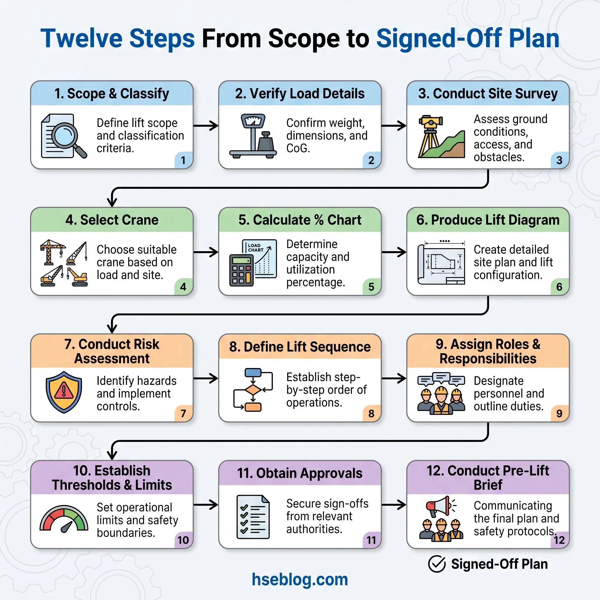
This is the sequence I follow for every non-routine lift. Each step produces a tangible part of the document; none can be skipped, and the order matters because later steps depend on decisions made earlier.
1. Define the scope and classify the lift. Write one paragraph describing the load, the pick point, the set-down point, and the operational context. Apply the four-tier classification. The output of this step is the category — routine, simple, complicated or complex/critical — because it determines which template, which approvals, and which level of detail the rest of the plan requires.
2. Verify the load. Get the weight from a design data sheet, shop drawing, nameplate or calibrated weigh cell. Record the source in the plan. For fabricated assemblies include rigging fit-up weight, insulation, internals, and any trapped fluid. Note centre of gravity and marked lifting points. A module I lifted last year came with a data sheet showing 38 tonnes; shop weighing before dispatch put it at 41.3 tonnes. That 9% delta would have pushed a 90% chart pick over the line.
3. Survey the site. Walk it, do not assume from drawings. Confirm ground conditions — bearing capacity from geotechnical data, slope, recent trenching, buried services. Identify overhead power lines and their voltage class; OSHA sets minimum approach distances keyed to voltage. Log proximity to occupied buildings, live process, public access. Photograph the pick and set zones from the crane position.
4. Select the crane and accessories. Using the load chart, pick a crane and configuration that lifts the gross load at the required radius with margin. Gross load means load plus rigging plus hook block plus any below-the-hook device. Derate for wind, angle of dangle, and any chart qualifiers. Select slings based on calculated tension at the included angle, not the straight-pull WLL.
5. Calculate capacity utilisation. Divide gross load by the chart capacity at the actual radius. If the answer sits above 75%, you have triggered critical-lift procedures in the US; above 70% is a sensible trigger anywhere. Document the calculation in the plan — not as a single line but showing inputs and result. An inspector will ask to see it.
6. Produce the lift diagram. Plan view showing crane footprint, outrigger positions and pad sizes, pick and set coordinates, radius circles at pick and set, swing path, exclusion zone, and any proximity hazards. Elevation view showing boom angle, hook height, clearance over obstructions at each stage. For congested sites, 3D Lift Plan or Cranimation produces a visual the whole team can interpret in the pre-lift brief.
7. Write the risk assessment. Identify hazards specific to this lift — not a copy of last month’s — and assign controls. The risk assessment feeds the plan; it is not a separate document filed in parallel.
8. Define the lift sequence. Step by step, numbered, each step tied to a diagram stage and a stop point. Include the trial lift, the brake test, the 300 mm verification, the swing, the set, and the disconnection sequence.
9. Assign roles and verify competence. Named people, named qualifications, named ticket expiry dates. If the supervisor’s CPCS card expires mid-lift-window, you have a problem — catch it here.
10. Set weather and stop-work thresholds. Maximum wind speed at boom tip, minimum visibility, lightning-proximity rule, rain/ice limit. Define who takes the anemometer reading, and how often. Write the stop-work triggers in plain language — “if any of the following occurs, the lift stops, the load is set down on the nearest safe position, and the supervisor is informed.”
11. Obtain approvals. AP signature, supervisor signature, client representative signature, and — for engineered lifts — PE stamp. For multi-crane or personnel lifts, add the third-party reviewer.
12. Brief the team in a pre-lift meeting. Walk through the plan, the diagram, the sequence, the stop-work triggers, the emergency response. Record attendance. Ask each person to repeat back their role and their stop authority. I learned this from a superintendent years ago: “if they cannot tell me back what they are going to do, I have not briefed them.”
Worked Example: A Simple Mobile Crane Lift
Consider a 4-tonne rooftop HVAC unit being set onto a six-storey commercial structure from a tarmac lay-down adjacent to the building.
- Scope: Lift one packaged AHU, verified weight 3,850 kg, dimensions 3.2 × 1.8 × 1.6 m, CoG marked, four certified lifting eyes. Pick from lay-down at ground level, place on roof steel at +21 m, radius 18 m from crane centre.
- Classification: Simple — single crane, known load, stable ground, no overhead power lines within 10 m.
- Crane selected: 90-tonne rough-terrain crane, 38 m main boom, full counterweight. Chart capacity at 18 m radius: 11.4 tonnes.
- Gross load: 3,850 kg (AHU) + 180 kg (slings and shackles) + 350 kg (hook block) = 4,380 kg.
- Capacity utilisation: 4,380 / 11,400 = 38%. Non-critical.
- Rigging: Four-leg 3 m wire rope sling, 2-tonne WLL per leg at 60° included angle, plus four 6.5-tonne bow shackles.
- Ground bearing: Tarmac confirmed by geotech report, 150 kN/m². Calculated outrigger pressure with 1.2 m² pads: 89 kN/m². Adequate with margin.
- Hazards: Pedestrian walkway 8 m from exclusion zone — closed and barriered for lift window. No power lines. Roof edge fall hazard for slingers at set-down — controlled by harness to certified anchor.
- Weather limits: wind speed at boom tip max 9.8 m/s; lift stops at 8 m/s for reassessment.
- Sequence: position crane, outriggers fully extended, pads level, attach rigging, trial lift 300 mm and hold 3 seconds, confirm stability, lift to 24 m, swing right 35°, lower onto marked steel position, two slingers on roof guide into place on tag lines, disconnect.
- Approvals: AP, Lift Supervisor, client rep.
- Brief: 06:45, crew of seven, stop-work triggers confirmed by each.
Filled in on a standard template, that is a simple lift plan. The reasoning behind each number is what makes it a real plan rather than a form.
Lifting Plan vs. Risk Assessment vs. Method Statement
These three documents get confused on almost every site I visit. They are related but distinct, and a good lifting plan references and integrates both of the others rather than replacing them.
A risk assessment identifies hazards and the controls that reduce risk to an acceptable level. It is required independently of LOLER under the Management of Health and Safety at Work Regulations (UK) and OSHA’s general duty clause (US). Its output is a list of hazards, likelihood, severity, and controls.
A method statement describes step by step how the work will be done — sequence, equipment, personnel, and controls applied at each stage. It operationalises the risk assessment.
A lifting plan integrates both of those — pulling in the hazards and controls from the risk assessment and the sequence from the method statement — and adds the lift-specific technical content: equipment selection, calculations, diagrams, competence records, and formal approvals.
| Document | Primary question answered | Required by | Typical author |
|---|---|---|---|
| Risk assessment | What could go wrong? | Management of H&S at Work Regs / OSHA GDC | Safety professional + line manager |
| Method statement | How will we do this work? | Client / contract / good practice | Supervisor or engineer |
| Lifting plan | How will we lift this load safely? | LOLER Reg 8 / OSHA Subpart CC | Appointed Person / qualified person |
On most projects the lifting plan cover sheet references the parent risk assessment and method statement by document number, so an auditor can trace the thread from “generic site risk” down to “this specific 3,850 kg pick at this specific radius at this specific time.”
Lift Diagrams and Calculations: The Technical Core
The diagram and the numbers are what separate a real lifting plan from a form-fill exercise. A plan without calculations is a description of intent, not an engineered control.
The plan view should show the crane in its working footprint with outriggers or tracks to scale, the pick and set positions with radius circles drawn from the crane slew centre, the swing path and any intermediate positions, the exclusion zone, and every proximity hazard within swing plus the length of the rigged load. The elevation view should show boom angle at pick and at set, hook height, load height, clearance to overhead structures and power lines, and any stages where the load transits over occupied areas.
The minimum calculations an Appointed Person must show on or alongside the plan:
- Gross load: load weight + rigging + hook block + below-the-hook devices.
- Capacity utilisation: gross load ÷ chart capacity at actual radius, expressed as a percentage.
- Sling tension: vertical leg load × reduction factor for the included angle (a 60° included angle gives roughly 1.15× the vertical load per leg; 90° gives 1.41×; 120° gives 2×).
- Ground bearing pressure: (crane weight + counterweight + load) ÷ total contact area of outrigger pads or track, compared against the ground’s allowable bearing capacity from geotech data.
- Radius check at every stage of the swing, not just at pick and set.
A Professional Engineer’s stamp is required for engineered lifts — custom below-the-hook lifting devices under ASME B30.20, lifts above certain thresholds set by the client or jurisdiction (commonly 50 tons in US heavy industry), unusual crane configurations, and any lift where the calculations go beyond chart interpolation. If the math involves anything other than reading a chart and applying standard factors, a PE should stamp it.
Software has made this faster and more defensible. 3D Lift Plan, Cranimation, Liebherr LICCON Plan, and LiftPlanner all produce scaled plan and elevation views, capacity check at every position in the swing, and exportable PDFs that go straight into the permit pack. Integration with BIM models and site digital twins is becoming the standard on major EPC and infrastructure projects — when the lift diagram sits inside the same model as the pipe rack and structural steel, clash detection is automatic. The warning I give every team adopting these tools: garbage in, garbage out. A 3D plan built on a guessed load weight is still a plan built on a guessed load weight.
Pre-Lift Meeting, Execution and Post-Lift Review
A lifting plan that is written, signed, filed and never briefed is worth nothing. Three execution gates separate the paper from the pick.
Before the lift. A pre-lift toolbox talk walks the crew through the plan, the diagram, the sequence, the stop-work triggers, and the emergency plan. Attendance is recorded. Each role confirms their duties and their stop-work authority. Ticket and medical currency is verified against the plan’s named personnel. Equipment certificates are physically checked against serial numbers on the crane and rigging. Weather is checked against the plan’s limits. The permit-to-lift is issued.
During the lift. OSHA 1926.1417(o) requires a trial lift and brake test for lifts at or above 75% of rated capacity — in practice many of us apply it to every non-routine lift. The discipline is the 3-3-3 rule: raise the load 300 mm off the ground, hold for 3 seconds, confirm stability with all personnel at least 3 metres clear of the load, then continue. The three seconds lets the operator feel how the load sits, hear any unusual noise from the crane, and confirm brake hold. If communication is lost during the lift — radio out, signaller out of sight — the rule is simple: the load stops, is placed on the nearest safe position if possible, and the lift pauses until communication is restored. Blind lifts (where the operator cannot see the load or landing) require a dedicated signaller with backup and a positively confirmed signal protocol.
After the lift. A short debrief while the crew is still on site captures what went as planned and what did not. Near-misses, deviations from the plan, and unexpected conditions feed back into the plan library so the next lift of the same class starts from a better baseline. This feedback loop is how planning quality improves over time — skip it and you keep making the same mistakes across different plans.
Watch For: A team that has done the same lift twenty times and stops briefing it. The twenty-first is the one that catches them out — new ground conditions, a different crew member, a load slightly out of spec. The brief is not for the lift; it is for the people doing it today.
Common Mistakes When Writing a Lifting Plan
Every one of these shows up in incident reports I have read or investigated. They are the failure patterns a good Appointed Person actively watches for.
- Copy-paste from a previous plan without re-verifying load, site, crane or team. Different day, different risk.
- Estimated load weights from memory, quotes, or “the supplier said so” — when the actual source should be a data sheet, weigh ticket or calculation.
- Rigging and hook-block weight ignored in the gross load — a routine omission that quietly pushes capacity utilisation past the critical threshold.
- No derating for wind, slope, or soft ground — the chart assumes ideal conditions that sites rarely provide.
- Complicated lifts classified as simple to avoid the heavier paperwork and approval chain — the category quietly shifts and the approvals do not catch up.
- Missing or expired certificates for crane, rigging, or personnel — caught only if someone checks dates against the plan.
- Undefined stop-work triggers — “stop if unsafe” is not a trigger; “stop if wind exceeds 8 m/s at boom tip” is.
- No lift diagram, or a diagram that shows pick and set but not swing path — the middle of the lift is where the clearance problem lives.
- Risk assessment filed separately and not reflected in the plan’s controls — hazards identified but not engineered out.
- No record of the pre-lift brief — if it is not signed, the regulator treats it as not having happened.
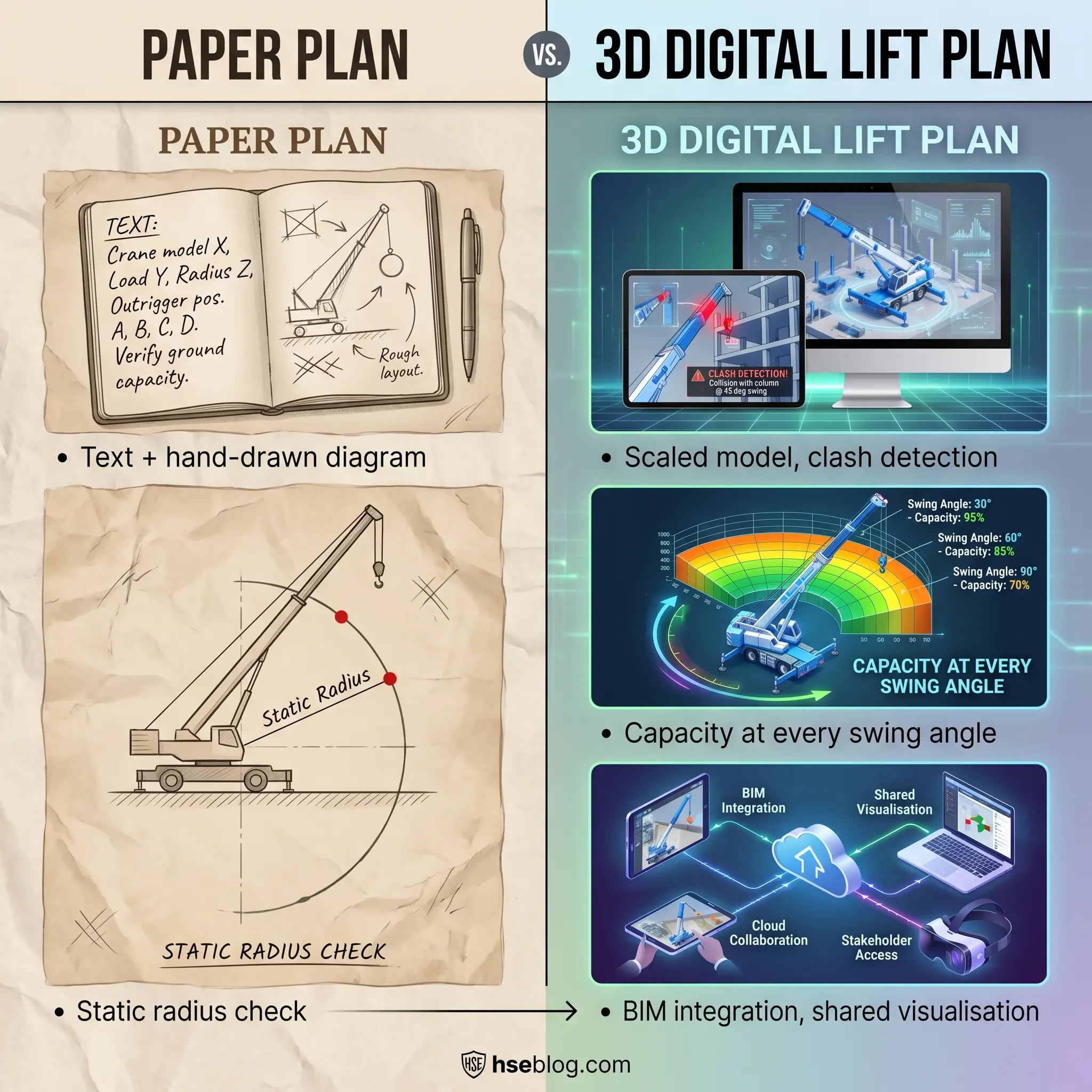
Digital Tools and 3D Lift Planning
The transition from paper plans to digital, model-based lift planning has accelerated through 2024 and into 2026, and on most major EPC and infrastructure projects it is now the default rather than the exception. Three shifts are worth naming.
First, 3D software — 3D Lift Plan, Cranimation, Liebherr LICCON Plan — produces scaled plan and elevation views, capacity utilisation at every swing angle, and visual outputs that stakeholders who do not read load charts can still interpret. For tandem lifts, the ability to model both cranes and their load-share at every point in the swing is transformative.
Second, BIM and digital-twin integration puts the lift inside the same environment as the structural model and construction schedule. Clash detection becomes automatic. A boom that fouls a yet-to-be-installed pipe rack gets caught in the model review, not in the field.
Third, cloud-based permit-to-lift and sign-off systems have shortened the approval cycle from days to hours. A plan updated at 03:00 to reflect a revised weather window can be re-signed by client, AP and supervisor before the 07:00 toolbox talk. The audit trail is automatic.
The caveat remains the same. The software does not verify your load weight, walk the site, or check the crane certificate. It makes a well-planned lift faster to document and easier to communicate. It does not turn a badly planned lift into a good one.
Frequently Asked Questions
Conclusion
A lifting plan is four things in one document: a legal record, an engineering calculation, an operational procedure, and a communication tool. Get those four right and the plan earns its place; get any of them wrong and the plan is paperwork. The decisions that matter most are the ones made before the crane rolls onto site — classify the lift honestly, verify the load from a real source, walk the site with your own eyes, calculate the numbers and put them in the plan, set stop-work triggers in language the crew can act on, and brief every person who will have hands on the lift. Sign it because you believe it, not because the form asks you to.
The direction of the industry is toward more integration, not less — 3D planning linked to BIM models, cloud permit systems tied to competence databases, ASME P30.1 and ISO 12480-1 pulling US and international practice closer together. The tools get better; the discipline underneath them is the same discipline BS 7121 wrote down decades ago. Plan, supervise, execute safely.
If a regulator walked onto your next lift and asked for the plan, the calculations, and the signatures, would you hand over a document you are proud of? That is the question every Appointed Person should answer on their own plans first — long before anyone else gets the chance to.