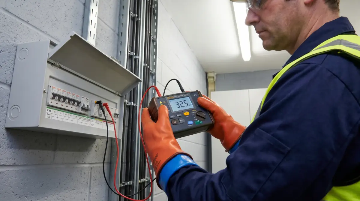
RCDs — known as GFCIs in the United States — detect dangerous earth leakage current and disconnect the circuit within milliseconds, preventing fatal electric shock. Push-button testing should occur every 6 months in the UK, monthly in the US, and between daily and 6-monthly in Australia depending on the work environment. Professional trip-time testing with calibrated instruments is required at least annually in most workplaces. Regular testing is essential because RCDs degrade mechanically over time: tripping mechanisms seize, contacts weld, and sensitivity deteriorates — all silently, with no external indication of failure.
What Is an RCD and How Does It Prevent Fatal Electric Shock?
Every circuit has current flowing out through the live conductor and returning through the neutral. In a healthy circuit, those two values balance. The moment current finds an alternative path to earth — through a person's body, through a damaged cable, through water — that balance breaks. An RCD monitors this balance continuously using a toroidal core wound with both the live and neutral conductors. When the difference between outgoing and returning current exceeds the device's rated sensitivity, typically 30mA, the tripping coil fires and disconnects the circuit.
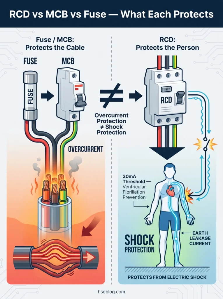
The 30mA threshold is not arbitrary. Research published under IEC 60479 established the time/current curves for electric shock effects on the human body. Currents above approximately 30mA sustained through the chest can induce ventricular fibrillation — the heart's electrical rhythm breaks down into chaotic, non-pumping contractions. A 30mA RCD that disconnects within 300 milliseconds keeps the shock exposure within the survivable zone of that curve.
This is fundamentally different from the protection a fuse or miniature circuit breaker provides. Fuses and MCBs respond to overcurrent — overloads and short circuits that could overheat cables and start fires. They protect the installation. An RCD protects the person. A circuit can deliver a lethal shock at currents far below the threshold that would blow any fuse. Without an RCD, the cable is safe while the person touching the fault is not.
RCDs come in three primary form factors, each serving different applications:
- Fixed RCDs installed in the consumer unit or distribution board, protecting entire circuits
- Socket-outlet RCDs built into individual power points, common in bathrooms and outdoor circuits
- Portable RCDs plugged into a socket before the equipment, used for temporary work and construction sites
An RCBO combines both RCD and MCB functions in a single device — detecting earth leakage and overcurrent independently. This distinction matters operationally because in a traditional split-load consumer unit, a single RCD protects multiple circuits. When it trips, everything downstream goes dark. An all-RCBO board isolates faults to individual circuits, eliminating the cascade problem.
| Protection Device | Protects Against | Does NOT Protect Against |
|---|---|---|
| Fuse / MCB | Overcurrent (overload, short circuit) | Earth leakage / electric shock |
| RCD (RCCB) | Earth leakage current to ground | Overcurrent, line-to-neutral shock |
| RCBO | Both earth leakage AND overcurrent | Line-to-neutral shock |
One misconception persists across workplaces and domestic properties alike: the belief that a tripping MCB or fuse means RCD protection is present. The MCB protects the cable. The RCD protects the person. These are separate functions, and conflating them is one of the most common — and most dangerous — misunderstandings in electrical safety.
Why RCD Testing Is a Life-Safety Priority
Between 2011 and 2023, 1,940 workers died from contact with electricity in the United States (ESFI, compiled from BLS CFOI data, 2025). That averages to roughly 150 workplace electrical fatalities per year. What makes this figure more troubling is the profile of the victims: 70% of those fatalities occurred in non-electrical occupations (ESFI/BLS, 2026) — construction labourers, maintenance workers, tree trimmers, and other trades where workers may not know whether RCD or GFCI protection is present, functional, or even required.
The situation is not limited to the US. The UK's Health and Safety Executive reports over 1,000 electricity-related workplace accidents per year, with approximately 30 fatalities (HSE UK, 2022/23 reporting period). More recently, ESFI data revealed a 59% increase in non-fatal electrical injuries involving days away from work in the US — 5,180 cases in 2023–2024 combined, up from 3,260 in the previous two-year period (ESFI/BLS, 2026). The trend line is moving in the wrong direction.
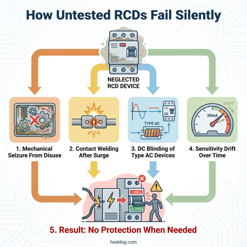
Fixed RCDs are approximately 97% reliable when properly maintained and regularly tested (Electrical Safety First / HSE UK). That figure degrades without periodic testing. The internal mechanism is mechanical — a spring-loaded trip coil that must physically separate contacts under load. Without regular operation, several degradation pathways activate silently:
- Mechanical seizure — the tripping mechanism corrodes or stiffens from disuse, preventing the spring from releasing
- Contact welding — a surge event fuses the internal contacts in the closed position; the device physically cannot disconnect
- DC component blinding — cumulative DC leakage from modern electronic loads desensitises Type AC devices, raising the effective trip threshold above the rated 30mA
- Sensitivity drift — environmental factors including moisture, dust ingress, and thermal cycling gradually shift the trip threshold
The most common failure pattern across the published record is the RCD that has never been tested since installation. In older properties and workplaces, it is routine to find devices that pass the push-button test but fail the professional trip-time test — they disconnect, but too slowly to prevent a lethal shock. A device tripping at 280ms instead of 25ms is technically within the 300ms BS 7671 limit, but it is no longer providing the rapid disconnection that keeps exposure within the survivable zone of the IEC 60479 time/current curve.
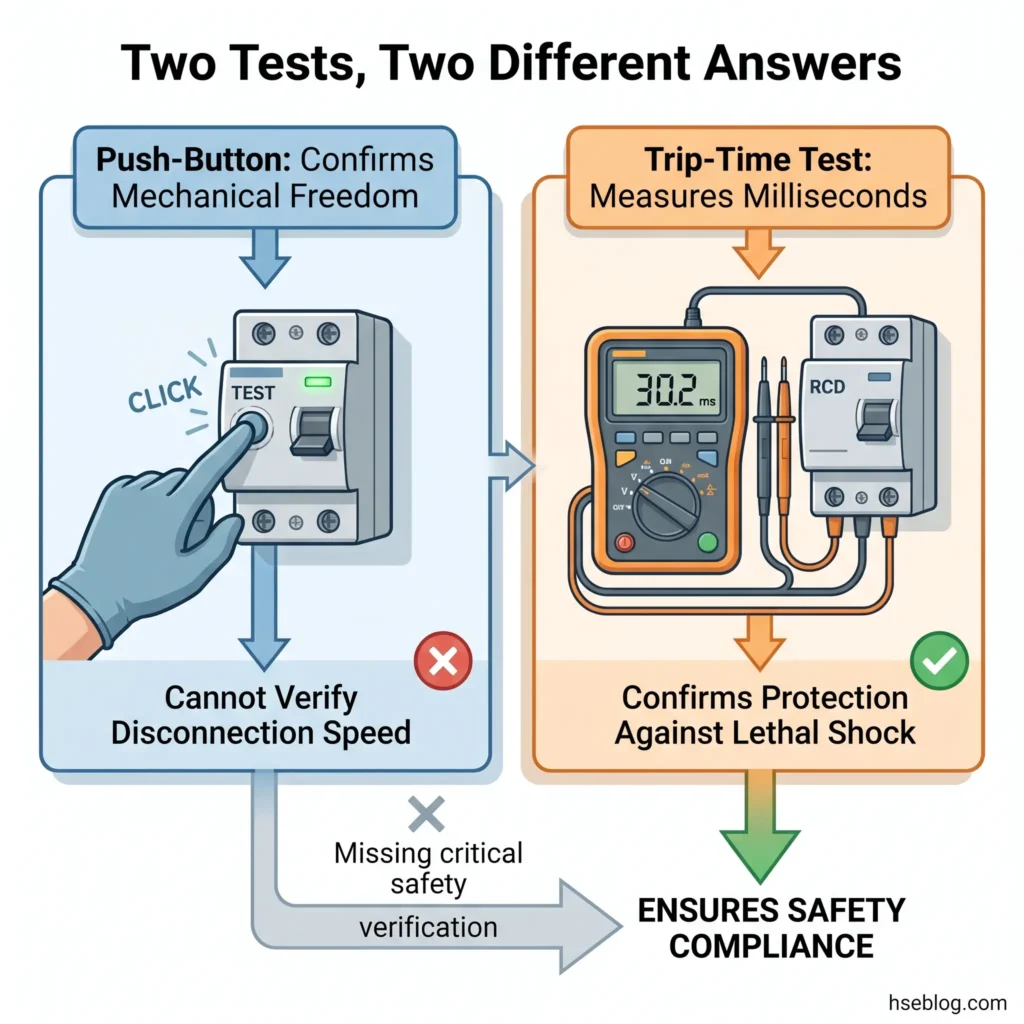
The push-button test alone creates a false sense of security. It confirms mechanical operation — the spring can release, the contacts can separate. What it cannot verify is whether the device will disconnect fast enough to prevent ventricular fibrillation when a fault occurs at full rated residual current. That distinction is the difference between a safety device and a safety assumption.
How Often Should You Test an RCD? Testing Frequency by Jurisdiction
Testing frequency depends on three variables: the jurisdiction you operate in, the type of RCD (fixed vs. portable), and the risk level of the environment. Critically, "testing" encompasses two distinct activities that many people — and most competitor guidance — conflate. The push-button test confirms mechanical function. The professional trip-time test with calibrated instruments verifies disconnection speed. Both are necessary, but they serve different purposes and occur at different intervals.
The table below synthesises the requirements across three major regulatory frameworks. No other publicly available guide currently presents these side by side, despite the fact that multinational organisations, facility managers, and HSE professionals frequently need to reconcile obligations across jurisdictions.
| Jurisdiction | Standard | Push-Button Test Interval | Professional Trip-Time Test Interval | Who Can Perform Trip-Time Test |
|---|---|---|---|---|
| UK | BS 7671:2018+A2:2022 | Every 6 months (fixed); before each use (portable) | At EICR interval: 5 years (domestic), 5 years (commercial) | Competent person per Electricity at Work Regulations 1989 |
| Australia / NZ | AS/NZS 3760:2022 | Daily/before use (construction); every 3–6 months (office/factory) | Every 3 months (construction); every 12 months (office/factory) | Competent person; records mandatory |
| US | OSHA §1926.404(b)(1); NEC 210.8; CPSC guidance | Monthly (CPSC recommendation); before each day's use (construction sites per OSHA) | No mandated federal interval; per manufacturer/employer program | Qualified person per OSHA definitions |
Several points of practitioner interpretation are worth noting here.
The shift from quarterly to six-monthly push-button testing in BS 7671's 18th Edition caught many in the UK industry off guard. The rationale, explained in IET Wiring Matters' coverage of changes to RCD testing in BS 7671 Amendment 2, was that the push-button test confirms mechanical freedom but does not verify trip time. The emphasis shifted to ensuring professional instrumented testing occurs at the appropriate EICR interval, where actual disconnection speed is measured.
Australia takes the most granular approach. Under AS/NZS 3760:2022, as implemented by SafeWork NSW, testing intervals scale directly with environmental risk. Construction sites — where portable electrical equipment operates in wet, dusty, and mechanically hostile conditions — demand daily push-button tests and quarterly professional tests. Offices, where conditions are controlled and equipment is largely static, operate on 6-monthly and 12-monthly cycles respectively.
The US framework is less prescriptive on testing intervals than either the UK or Australian models. OSHA requires GFCI protection on construction sites for 125V, single-phase, 15–30A receptacles not part of permanent wiring under 29 CFR 1926.404(b)(1)(ii), and mandates "frequent and regular inspections." The CPSC recommends monthly push-button testing for household GFCIs. The NEC 2023 cycle expanded GFCI protection requirements to 125–250V receptacles across 15 specified location types, but testing frequency remains driven by manufacturer instructions and employer safety programs rather than a fixed regulatory interval.
Jurisdiction Note: The US GFCI Class A standard (UL 943) specifies a trip threshold of 4–6mA, while UK/EU/AU RCDs are standardised at 30mA rated residual current. The US threshold is significantly more sensitive because GFCI was designed exclusively for personal protection. The 30mA threshold balances personal protection with operational tolerance for cumulative leakage across a circuit. Neither is inherently "safer" — they are calibrated to different operational assumptions. Always state jurisdiction when comparing trip thresholds.
Push-Button Test vs. Professional Trip-Time Test: What Each Actually Proves
This distinction is the single most important concept that current guidance on this topic fails to explain adequately. Understanding what each test measures — and what it cannot measure — is the difference between confirmed protection and assumed protection.
The push-button test simulates an earth fault internally. When you press the T or Test button on an RCD, it creates an artificial imbalance in the toroidal core by passing a small current through a test resistor. If the mechanical tripping mechanism is free, the device disconnects. This confirms that the spring can release and the contacts can separate. It does not measure how quickly the device disconnects, nor does it verify that the device would respond to a real external fault at its rated sensitivity.
Anyone can perform a push-button test. No instruments are required. It takes seconds. It should be part of routine checks at the intervals specified above.
The professional trip-time test uses a calibrated instrument complying with BS EN 61557-6 to inject a controlled simulated fault current and measure the disconnection time to the millisecond. Under BS 7671:2018+A2:2022, Regulation 643.7.1 and 643.8, the test protocol is now:
- Test at ½× rated residual current (½×IΔn) — the device must NOT trip. This confirms the RCD is not over-sensitive, which would cause nuisance tripping
- Test at 1× rated residual current (1×IΔn) — the device MUST trip within 300ms for non-delay types, or 130–500ms for S-type (selective/time-delay) RCDs
- Record the measured trip time in the EICR or test certificate
A significant change under Amendment 2 (2022) was the removal of the mandatory 5× test. Previously, RCDs had to be tested at five times the rated residual current (5×IΔn) with a maximum 40ms disconnection time. This test was intended to verify rapid disconnection under high-fault conditions, but the IET determined that the 1× test at 300ms provided an adequate compliance benchmark. The 5× test remains available as an optional verification but is no longer a pass/fail requirement.
Watch For: RCDs that pass the push-button test but show trip times in the 200–280ms range on instrumented testing. These devices are technically within the 300ms limit, but they are no longer providing the sub-40ms disconnection that a healthy device delivers. Progressive slowing across successive test cycles is a strong indicator that the device is approaching end of life.
How to Test Your RCD: Step-by-Step Procedure
The push-button test is something every person with access to an electrical installation can and should perform. It requires no instruments, no qualifications, and no special tools. What it does require is a few minutes of preparation to avoid disrupting sensitive equipment unnecessarily.
Before you begin, save any open work on computers connected to circuits protected by the RCD. Turn off or unplug equipment that could be damaged by a sudden power interruption — desktop computers mid-update, recording equipment, aquarium heaters, or medical devices. If the RCD protects a freezer circuit, plan the test for a time when a brief power interruption won't compromise stored food.
The push-button test procedure for a fixed RCD in a consumer unit or distribution board follows these steps:
- Identify which RCD protects which circuits. The consumer unit should have a circuit chart. If not, this is itself a compliance gap worth flagging
- Press the button marked T or Test firmly. The RCD should trip immediately — you will hear a click and the toggle will move to the off or tripped position
- Verify that power is off on protected circuits. Check lights, sockets, or use a socket tester on downstream outlets. If power remains on, the RCD may be bypassed or wired incorrectly — this requires immediate professional investigation
- Reset the RCD. Switch the toggle fully to the OFF position first, then switch it to ON. Do not simply push the toggle back up from the tripped position
- Confirm circuits are restored. Check that lights and equipment downstream are functioning normally
- Record the test. Date, result, any anomalies. In workplace settings, this record is a legal compliance document
The reset sequence in step 4 matters more than it appears. After tripping, the internal contacts may be in an intermediate state. Switching fully off before switching on ensures the contacts re-engage completely. Incomplete reset — where the toggle appears to be in the on position but the contacts have not fully closed — creates what practitioners call "phantom protection." The switch looks right, but the circuit is either unprotected or intermittently connected.
Field Test: For portable RCDs — the plug-in type used with power tools and temporary equipment — the test protocol is the same but the timing is different. Test before every use. Every single time. Portable RCDs operate in harsher conditions than fixed devices: they are dropped, exposed to dust and moisture, and connected to high-vibration equipment. Their failure rate is correspondingly higher.
If the RCD does not trip when the test button is pressed, do not use the protected circuits. Isolate the circuit at the main switch if possible and engage a qualified electrician. A non-tripping RCD is not a minor fault — it means the device that stands between a person and a fatal shock is not functioning.
Types of RCD and How Type Affects Testing Requirements
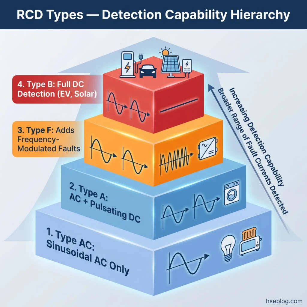
Not all RCDs detect the same kinds of fault current, and this has direct implications for both protection adequacy and testing. The type classification — printed on the device face — determines which fault waveforms the RCD can sense and respond to.
| RCD Type | Fault Current Detection | Typical Application | BS 7671 Status |
|---|---|---|---|
| Type AC | Sinusoidal AC only | Fixed resistive loads (legacy) | Restricted — not suitable for most new circuits |
| Type A | AC + pulsating DC | General-purpose — the default for most circuits | Current general-purpose standard |
| Type F | AC + pulsating DC + frequency-modulated faults | Inverter-driven loads (heat pumps, some HVAC) | Required for specific frequency-sensitive loads |
| Type B | Full DC fault detection | EV charging installations, photovoltaic systems | Mandatory under BS 7671 Section 722 for EV charging |
BS 7671:2018+A2:2022 effectively retired Type AC for most new installations. The reasoning is straightforward: modern buildings are no longer purely resistive loads. LED drivers, switch-mode power supplies, variable-speed drives, EV chargers, and photovoltaic inverters all produce DC or mixed-waveform leakage components. A Type AC RCD, designed exclusively for sinusoidal AC faults, simply cannot see these components. Cumulative DC leakage can saturate the toroidal core and "blind" the device — raising the effective trip threshold well above 30mA without any external indication of failure.
The proliferation of electronic loads means that cumulative DC leakage current across a circuit is now a real operational concern, not a theoretical one. Type AC RCDs installed before Amendment 2 may be technically compliant with the version under which they were installed, but they represent a declining standard of protection in any building with modern appliances, inverter-driven equipment, or EV charging.
The shift to Type B RCDs for EV charging, mandated under BS 7671 Section 722, is the most visible example of how load characteristics drive RCD selection. An EV charger with an onboard rectifier can produce smooth DC fault current that a Type A device cannot detect. A Type B RCD monitors the full frequency spectrum including pure DC — the only device type that can guarantee disconnection under all fault conditions at an EV charging point.
Amendment 3 (2024) further refined RCD selection criteria and extended AFDD (Arc Fault Detection Device) protection requirements to higher-risk residential buildings, including houses of multiple occupation, student accommodation, and care homes. While AFDDs address a different hazard mechanism — series arc faults that produce fire rather than shock — their introduction alongside evolving RCD requirements reflects the broader trend: the electrical installation is becoming more complex, and the protection devices must evolve to match.
What Happens When an RCD Fails? Consequences and Common Failure Modes
An RCD that fails is invisible. Unlike a tripped breaker that leaves the lights off or a blown fuse that stops the socket working, a failed RCD sits in the consumer unit with its toggle in the ON position, connected to live circuits, providing no protection whatsoever. The circuit works normally. Equipment runs. Lights come on. Everything looks correct — right up to the moment someone touches a live fault and the device that should save their life does nothing.
The most dangerous failure is the one nobody notices until a fault occurs. The RCD that trips too easily — nuisance tripping — gets immediate attention because it is disruptive. The RCD that cannot trip gets none, because silence and normal operation are indistinguishable.
Failure modes fall into several distinct categories, each with different causes and warning signs:
Mechanical seizure is the most common failure in devices that are never push-button tested. The tripping mechanism relies on a spring-loaded plunger acting against mechanical contacts. Without periodic operation, corrosion builds on pivot points, lubricants dry, and the spring-loaded mechanism stiffens. Over months and years, the force required to trip the device exceeds what the tripping coil can deliver. The push-button test exists precisely to prevent this — regular operation keeps the mechanism free.
Contact welding occurs when a significant surge event — lightning, switching transients, or a major short circuit on the protected circuit — forces the internal contacts together with enough energy to fuse them. Once welded, the contacts cannot separate regardless of what the tripping coil does. The device is permanently closed. This failure mode is undetectable by push-button test alone because the test button operates a different part of the mechanism.
DC blinding affects Type AC devices exposed to cumulative DC leakage from electronic loads. The DC component partially saturates the toroidal core, reducing its sensitivity to AC imbalance. The effective trip threshold creeps upward — from 30mA to 50mA, 80mA, or higher — without any external indication. The device may still trip on the push-button test (which uses an internal AC test circuit) while being functionally blind to real-world mixed-waveform faults.
Wiring faults bypassing the RCD are not a device failure but an installation failure that produces the same outcome. A borrowed neutral — where a circuit's neutral conductor connects downstream of one RCD but its live conductor is fed from another — creates a permanent imbalance that either causes continuous nuisance tripping or, worse, routes fault current through a path that the RCD does not monitor. These faults are only detectable through systematic insulation resistance testing and circuit verification during an EICR.
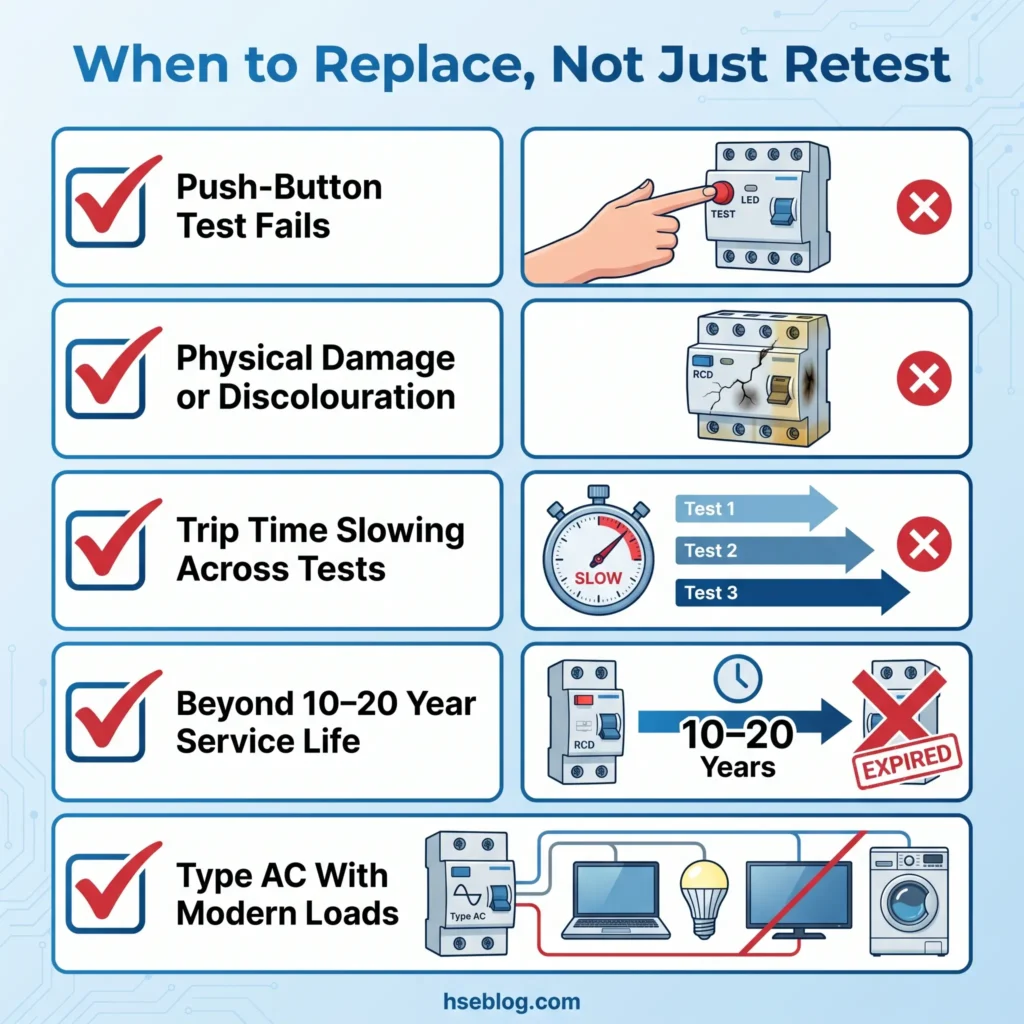
RCDs are not immortal devices. Manufacturer guidance typically specifies a service life of 10–20 years depending on environment and usage patterns. Beyond that window, degradation across all four mechanisms accelerates, and the probability of the device failing when called upon increases significantly.
When Must RCDs Be Replaced, Not Just Tested?
Testing naturally leads to the replacement question: at what point does a test result indicate that the device should be removed from service rather than simply retested at the next interval?
The clearest replacement trigger is a failed push-button test. If the RCD does not trip when the test button is pressed, it must be replaced. There is no repair pathway for a seized mechanism or welded contacts — the device is a sealed unit. Similarly, physical damage — cracked housings, discolouration from overheating, burn marks, or a persistent acrid smell — warrants immediate replacement regardless of test results.
Trip-time trending provides a subtler but equally important signal. A healthy 30mA RCD typically trips in under 30ms at rated residual current. If successive instrumented tests — recorded during periodic EICR inspections — show progressive slowing from, say, 22ms to 85ms to 180ms across three test cycles, the trajectory points clearly toward eventual failure. Waiting until the device exceeds the 300ms limit is waiting too long. The judgment call for a practitioner is whether to replace at the point where the trend becomes clear, or to wait for a formal fail. The operationally sound approach is to replace proactively when trending data shows consistent degradation.
On an EICR, a failed RCD typically generates a C2 observation code (potentially dangerous — urgent remedial action required) or, in severe cases, a C1 code (danger present — immediate risk). Either code has consequences beyond safety: it can affect building insurance validity, landlord compliance under the Electrical Safety Standards in the Private Rented Sector (England) Regulations 2020, and property transaction due diligence. Under those Regulations, landlords in England must ensure electrical installations are inspected and tested at least every 5 years, and non-compliance carries fines of up to £30,000 (UK Government, 2020).
In practice, RCD replacement is most commonly triggered by a consumer unit upgrade rather than a standalone failure. When a distribution board is replaced, the opportunity arises to move from a traditional dual-RCD split-load configuration to an all-RCBO board. This eliminates the nuisance-tripping problem where a single earth-leakage fault on one circuit disconnects half the property. It also allows each circuit to be individually protected and individually tested — a significant improvement in both safety granularity and operational convenience.
Upgrading Type AC devices to Type A or Type B during a consumer unit replacement is no longer optional good practice — BS 7671:2018+A2:2022 requires it for new and altered circuits. The upgrade addresses both the DC blinding vulnerability and the expanded GFCI/RCD protection now required for circuits serving modern electronic loads and EV charging.
Frequently Asked Questions
Can I test my RCD myself, or do I need an electrician?
You can and should perform the push-button test yourself at the intervals your jurisdiction requires — every 6 months in the UK, monthly for US GFCIs, and between daily and 6-monthly in Australia depending on the work environment. This test requires no instruments or qualifications. The professional trip-time test, however, requires a competent person using calibrated instruments complying with BS EN 61557-6. That test measures actual disconnection speed in milliseconds and cannot be performed without specialised equipment.
What does it mean if my RCD keeps tripping for no apparent reason?
Nuisance tripping always has a cause — it is not random. The RCD is detecting cumulative earth leakage from multiple appliances on the protected circuit that, combined, approach or exceed the 30mA threshold. Common contributors include ageing appliances with degrading insulation, moisture ingress in outdoor circuits, or faulty heating elements. Systematically unplug appliances one at a time and reset the RCD to isolate which device is contributing the highest leakage. A persistent problem after isolation warrants professional insulation resistance testing.
Is an RCD the same as a GFCI?
Functionally, yes — both detect earth leakage current and disconnect the circuit to prevent electric shock. RCD is the term used in the UK, EU, and Australia/New Zealand. GFCI (Ground Fault Circuit Interrupter) is the US term. The key technical difference is the trip threshold: US GFCI Class A devices (per UL 943) operate at 4–6mA, while UK/EU/AU RCDs are standardised at 30mA. The US threshold is more sensitive because GFCI was designed exclusively for personal protection, whereas 30mA RCDs balance personal protection with tolerance for cumulative leakage across a full circuit.
Can an RCD protect you from all types of electric shock?
No. An RCD protects against earth-fault currents — situations where live current leaks to earth through a person, a cable fault, or equipment damage. It cannot protect against line-to-neutral contact, where someone simultaneously touches both the live and neutral conductors. In that scenario, current flows through the person but the circuit appears balanced to the RCD because no current is "leaking" to earth. This is a fundamental design limitation, not a defect. Supplementary protection — insulation, barriers, safe working distances — remains essential.
How long should an RCD take to trip?
Under BS 7671:2018+A2:2022 (UK), a standard non-delay 30mA RCD must disconnect within 300ms at rated residual current (1×IΔn). S-type (time-delay) RCDs have a 130–500ms window. In practice, a healthy general-type device trips in under 30ms. The mandatory 5× test — requiring disconnection within 40ms at five times rated residual current — was removed by Amendment 2 in 2022. The 1× test at 300ms is now the compliance benchmark, though the 5× test can still be performed as optional verification.
Does RCD testing affect my EICR or insurance?
A failed RCD test during an EICR will result in either a C2 code (potentially dangerous — urgent remedial action required) or a C1 code (danger present). Either code means the installation does not meet the required standard. For landlords in England, this has direct consequences: the Electrical Safety Standards in the Private Rented Sector Regulations 2020 require a satisfactory EICR at least every 5 years, and non-compliance carries fines of up to £30,000. Building insurers may also query policy validity if a known electrical defect remains unremedied.
Conclusion
Electrical safety turns on devices that work silently and fail silently. The RCD in a consumer unit draws no attention when it is functioning correctly — and draws no attention when it has seized, welded, or drifted beyond its rated sensitivity. That silence is the hazard. Between 2011 and 2023, 1,940 workers died from electrical contact in the US alone (ESFI/BLS, 2025), and the majority of those deaths occurred among workers in non-electrical occupations who may never have known whether RCD or GFCI protection was present on the circuits they used.
The testing obligation is not complex. Press the button at the required interval — six months in the UK, monthly in the US, daily on Australian construction sites. Ensure professional trip-time testing occurs with calibrated instruments at each EICR or periodic verification cycle. Record every result. When trip times trend upward across successive tests, or when the device has reached the end of its manufacturer-specified service life, replace it. When a consumer unit is upgraded, move to an all-RCBO configuration and ensure every new RCD is Type A or better — not Type AC.
Every one of these actions is simple. Every one of them takes minutes. The consequence of skipping them is a protection device that exists in name only — a toggle switch in the ON position, connected to live circuits, incapable of doing the one thing it was installed to do. The people downstream of that device are relying on it with their lives. The least we owe them is to test it.