
TL;DR
- Isolate, then verify. Safe isolation means disconnecting, securing, and proving a circuit dead — not just flipping a switch or trusting a label.
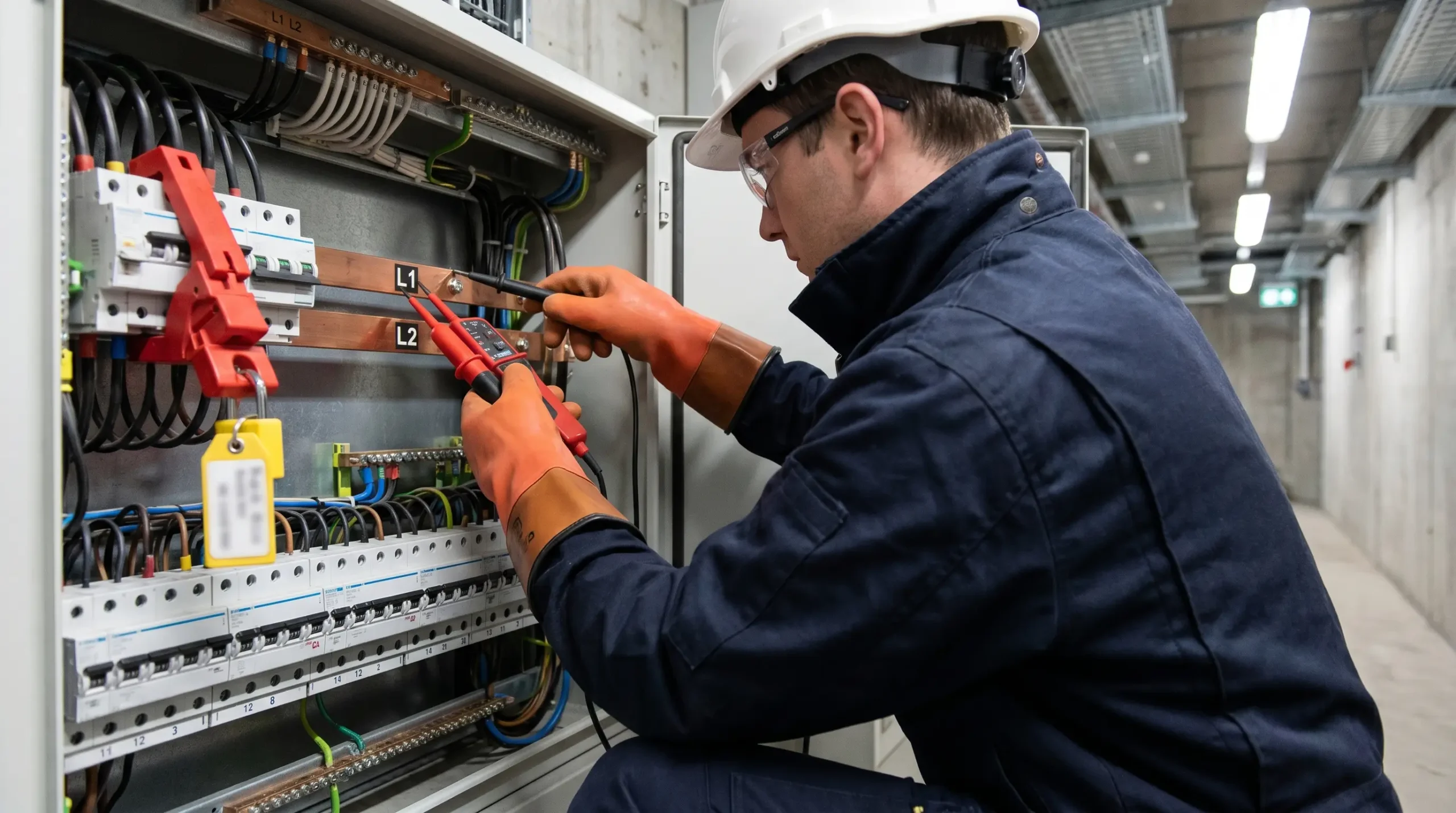
- Use GS38-compliant equipment. A two-pole voltage indicator tested on a proving unit is mandatory; multimeters and voltage sticks are not acceptable for proving dead.
- Lock off, never just off. Apply a personal padlock via a matched lock-off device, retain the only key, and fit a warning tag identifying the person and work.
- Test every combination. Single-phase requires three tests; three-phase requires ten — including neutral-to-earth and every phase pairing.
- Restore in reverse. Re-energisation kills when people remain inside cabinets or tools are left behind — follow the documented reverse sequence before restoring supply.
Safe isolation is the controlled process of disconnecting electrical equipment from every source of supply, physically securing that disconnection with a lock and tag, and verifying the circuit is dead using GS38-compliant test equipment at the point of work — a legal duty under the Electricity at Work Regulations 1989 and equivalent standards internationally.
Regulation 14 of the Electricity at Work Regulations 1989 sets a default position most people outside electrical work never realise exists. You do not work on or near a live conductor unless three conditions are simultaneously met: it must be unreasonable to make it dead, it must be reasonable in the circumstances to work it live, and suitable precautions must prevent injury. Dead working is not the preferred option in UK law — it is the starting point. Everything else is an exception that must be justified in writing.
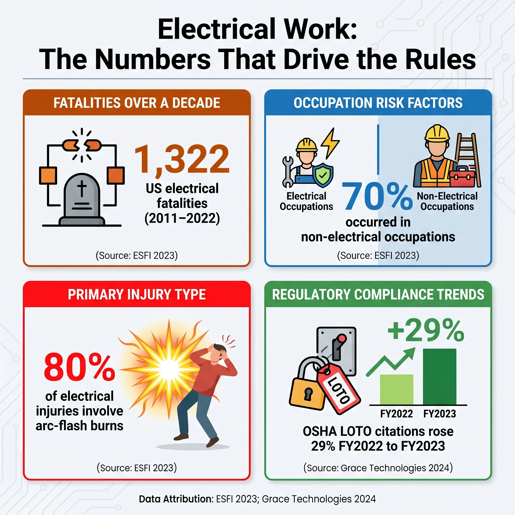
Getting safe isolation wrong costs lives, limbs, and liberty. Between 2011 and 2022, 1,322 workplace electrical fatalities occurred in the United States, with 70% in non-electrical occupations (Electrical Safety Foundation International, 2023). In the UK, over 1,000 electricity-related workplace accidents are reported each year, with approximately 30 resulting in fatalities (HSE data, cited via OSHA Online Center). This article walks through the safe isolation procedure step by step — from legal duty and preparation, through the full dead-testing sequence, to the reverse procedure for restoring supply — so site teams, supervisors, and HSE officers have a single definitive reference.
What Is Safe Isolation?
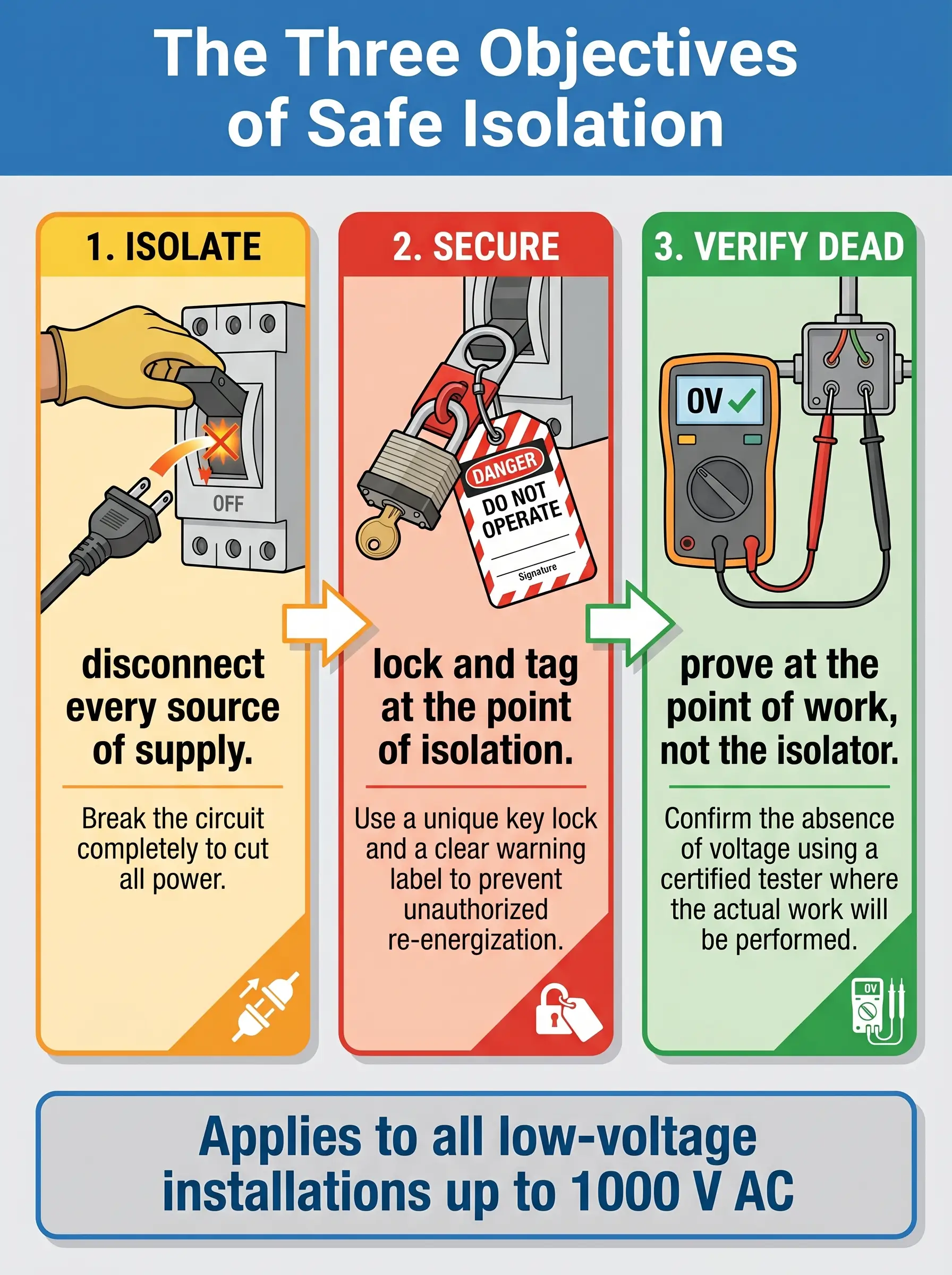
Safe isolation is a defined sequence of actions that renders electrical equipment dead and keeps it dead while work is carried out. The procedure applies to low-voltage installations up to 1000 V AC and 1500 V DC, but the underlying discipline — isolate, secure, verify — extends to every form of hazardous energy on site.
“Switched off” is not interchangeable with “isolated.” A functional switch interrupts current flow for operational purposes. It may not disconnect all poles, may be remotely or automatically re-operated, and offers no secure barrier against re-energisation. Isolation uses a device designed specifically to provide secure disconnection, typically with a visible break or a verifiable open-contact position.
Three objectives govern every isolation:
- Isolate — physically disconnect the circuit from every source of supply, including secondary supplies such as UPS, generators, and PV.
- Secure — lock the disconnection point and tag it so no one can re-energise while work proceeds.
- Verify dead — test at the point of work using compliant equipment proved immediately before and after the test.
A circuit is not isolated until all three objectives have been independently achieved. Miss one, and the procedure has failed even if nothing visibly goes wrong.
Jurisdiction Note: The UK uses the term “safe isolation.” In the US, NFPA 70E Article 120 describes the same discipline as “establishing an electrically safe work condition,” carried out within a Lockout/Tagout programme under OSHA 29 CFR 1910.147. The procedural logic is identical; the terminology and documentation differ.
Why Safe Isolation Matters: The Risk of Getting It Wrong
The numbers behind electrical work tell a consistent story. In the United States, 1,940 electrical fatalities occurred out of 70,692 total occupational deaths between 2011 and 2023 (Electrical Safety Foundation International / U.S. Bureau of Labor Statistics). Seventy percent of those electrical deaths occurred in non-electrical occupations — workers who encountered hidden energised conductors during maintenance, demolition, or adjacent trades rather than specialist electricians. In 2019 alone, 166 US workplace deaths from electrocution were reported — a 3.75% increase over the previous year (U.S. Bureau of Labor Statistics, 2021).
Three distinct hazards make electrical work unforgiving:
- Electric shock — current passes through the body; ventricular fibrillation can occur at currents well under 100 mA for durations under a second.
- Arc flash — explosive thermal release from a short circuit; peak temperatures exceed those of the sun’s surface within milliseconds.
- Arc blast — the pressure wave accompanying an arc flash, throwing workers, launching molten metal, and rupturing eardrums.
Up to 80% of OSHA-reported electrical injuries involve thermal burns from arc flashes (Grace Technologies 2024 State of Electrical Safety Report). The ESFI workplace injury and fatality dataset shows the same pattern repeating across industries and decades.
The common factor in most incidents is not deliberate live working. It is the gap between switching off and confirming dead — the space where assumption substitutes for verification. Short-duration tasks carry disproportionate fatality rates. “Just a quick lamp change” or “I only need a minute at that contactor” are recurring phrases in the published incident record.
The regulatory signal reinforces the point. OSHA Lockout/Tagout citations rose 29% from 1,968 in FY2022 to 2,532 in FY2023, carrying $20.7 million in penalties (Grace Technologies 2024 State of Electrical Safety Report), and LOTO remains fixed in OSHA’s Top 10 most-cited violations list (OSHA annual citation data). Isolation failure is not a historical problem. It is a live compliance issue, year on year.
The Legal and Regulatory Framework
The legal duty to isolate before work crosses jurisdictions, though the terminology differs. In the UK, Regulation 13 of the Electricity at Work Regulations 1989 requires adequate precautions to prevent equipment made dead from becoming live while persons are working on or near it — the explicit legal basis for locking off. Regulation 14 establishes dead working as the default, permitting live work only when all three of its conditions are met simultaneously. Regulation 16 fixes competence as a prerequisite for anyone undertaking electrical work.
The practical code is HSG85 — Electricity at Work: Safe Working Practices — the HSE’s authoritative interpretation of the regulations for duty holders. Guidance Note GS38 (4th Edition) specifies the equipment standard for test leads, probes, voltage indicators, and proving units, and the full GS38 document is published at hse.gov.uk. Two product standards underpin GS38: BS EN 61243-3 for two-pole low-voltage voltage detectors, and BS EN 61010, which defines the CAT II, III, and IV ratings for measurement equipment.
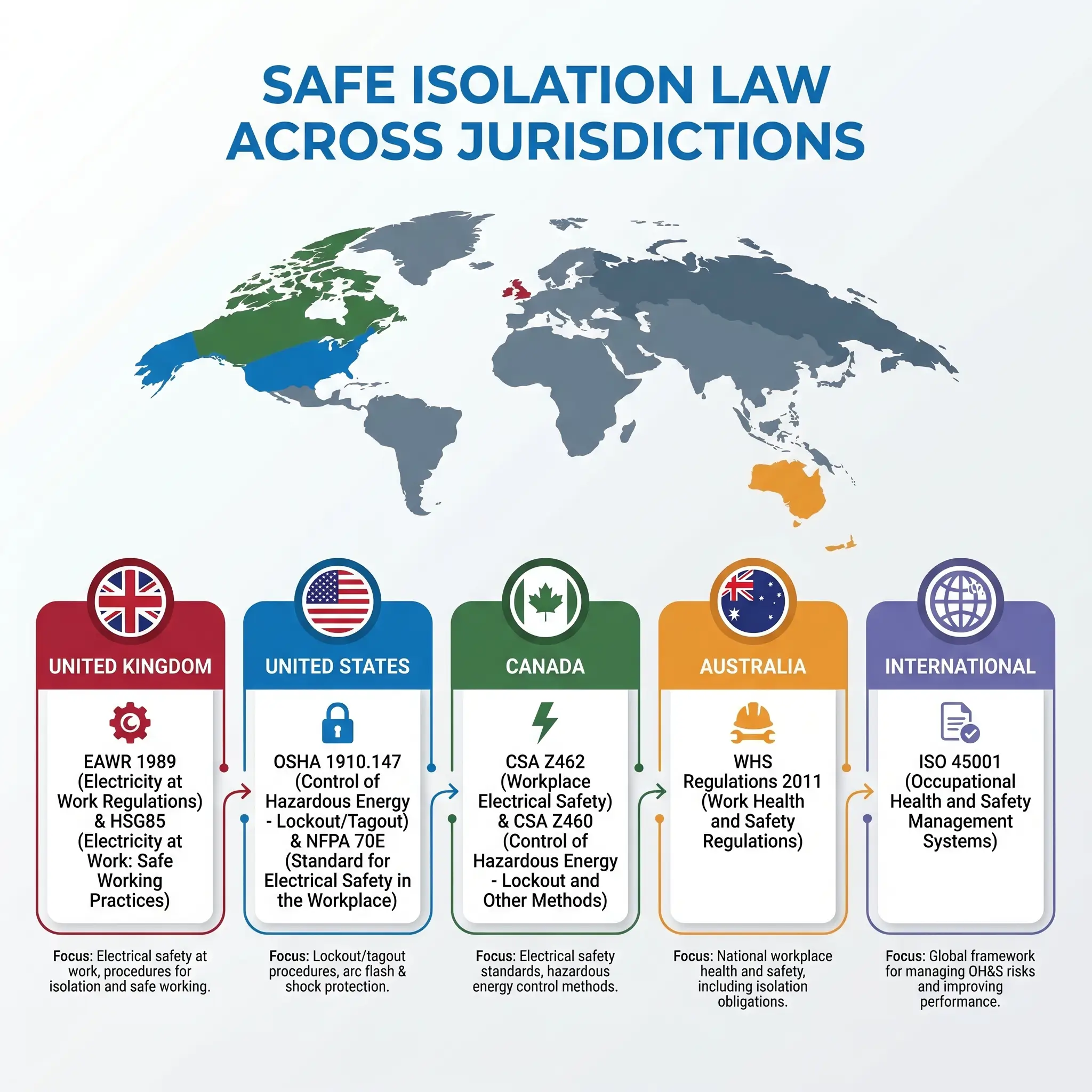
Outside the UK, the same duty is framed differently:
| Region | Primary Standard | Core Duty |
|---|---|---|
| United Kingdom | EAWR 1989 (Reg 13, 14, 16); HSG85; GS38 | Dead working as default; competence required |
| United States | OSHA 29 CFR 1910.147; NFPA 70E Article 120 | Written LOTO programs; electrically safe work condition |
| Canada | CSA Z462; CSA Z460 | Workplace electrical safety; hazardous energy control |
| Australia | WHS Regulations 2011 (model) | Risk assessment and secured isolation |
| International | ISO 45001 | Hazardous energy control within OH&S management |
The live-work exception in EAWR Regulation 14 is widely misunderstood. All three conditions must be satisfied together — not any two of three. An installation where dead working is merely “inconvenient” or “would extend the job” does not satisfy the first condition. Regulators and auditors read the clause strictly, and enforcement notices consistently reference failures at exactly this test.
Important: This article provides general HSE knowledge. Live electrical work and the planning of safe isolation must be carried out and supervised by a competent person with relevant training, jurisdiction-specific authorisation, and a site-specific risk assessment. Recognised training pathways include City & Guilds 2365/2391 (UK), NEBOSH, IOSH, OSHA 10/30 (US), and CSA-accredited programmes (Canada). The information here does not replace formal training or authorisation.
Who Counts as a Competent Person?
Competence under EAWR Regulation 16 is not a single qualification — it is a combination. The regulation requires adequate knowledge of electricity, adequate experience of electrical work, adequate understanding of the specific system being worked on, practical experience of that class of system, understanding of the hazards that may arise, and the ability to recognise when to stop and seek further advice.
The judgment call sits with the employer or duty holder. A qualified electrician with twenty years in domestic installations is not automatically competent to isolate a 400 V three-phase industrial distribution board. Competence is system-specific, site-specific, and — for higher-risk environments — almost always authorisation-based.
Authorisation is the site-level control layered on top of competence. Most industrial, commercial, and infrastructure sites operate a written authorisation scheme specifying who may isolate what, up to which voltage, under which permit regime. The authorisation list is reviewed, renewed, and withdrawable. A person whose authorisation has lapsed is, for the purposes of that work, not competent — regardless of underlying qualification.
Unauthorised isolation, even in an emergency, creates liability exposure and risk. The correct emergency response is to contact the authorised person or the duty holder, not to attempt isolation beyond one’s authorisation.
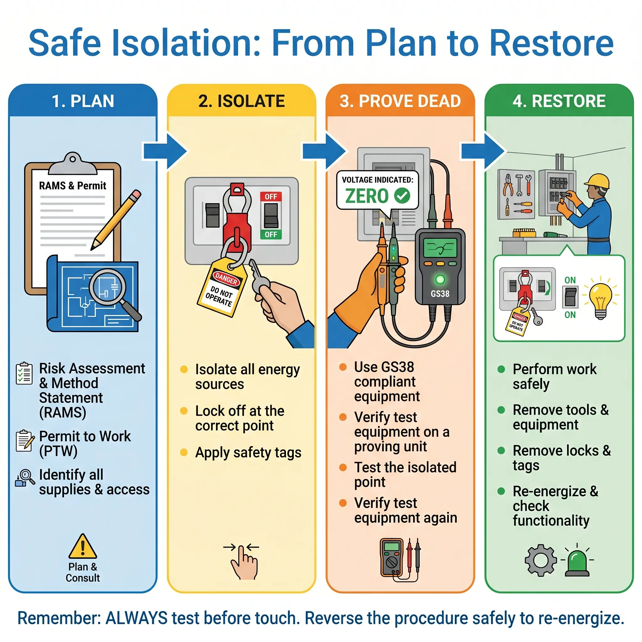
Before You Begin: Preparation and Permissions
Most isolation failures start before any tool touches any screw. They start at the planning stage — the wrong circuit is identified from a mislabelled schedule, a secondary supply is not documented, no permit is issued, affected persons are not informed.
The preparation sequence any competent planner works through:
- Complete the Risk Assessment and Method Statement (RAMS). Identify the hazards specific to this isolation — not a generic template copied from a previous job.
- Obtain formal permission from the duty holder or responsible person. Verbal agreement without written authorisation is not permission.
- Issue a Permit to Work where required. Permits are typically mandated for HV work, shared systems, multiple concurrent trades, safety-critical installations, or where the RAMS identifies high residual risk.
- Identify every source of supply. Mains, standby generators, UPS, solar PV, power-factor correction banks, battery backup, interconnected systems, and any automatic transfer switches.
- Review drawings and as-installed records. Circuit schedules are frequently wrong, and labels on boards are frequently older than the current installation they pretend to describe.
- Inform all affected persons. Anyone relying on the supply — production lines, process control rooms, IT systems, adjacent tenants, life-safety equipment — must know of the outage before it occurs.
- Assemble the correct test and lock-off kit. Check calibration, battery state, and physical condition before leaving the tool store.
A consistent failure at this stage is accepting a verbal assurance that “nothing else feeds that panel.” Secondary supplies are the category most likely to cause unexpected re-energisation during work, and a verbal assurance is not a verification. Electrical Safety First’s Best Practice Guide 2 walks through the preparation stage in detail and is worth consulting alongside internal site procedures.
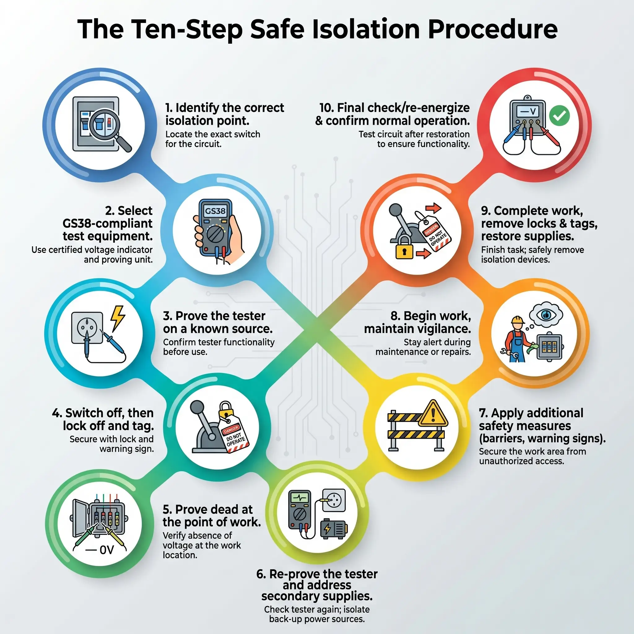
The Step-by-Step Safe Isolation Procedure
What follows is the defined ten-step sequence. Each step has its own purpose, its own failure mode, and its own verification. Skipping or compressing any step is where the procedure breaks — and where the incident follows.
Step 1 — Identify the Correct Point of Isolation
Positive identification means tracing the circuit from the point of work back to the isolator and confirming, independently, that the device selected actually controls the intended conductors. Circuit labels on distribution boards are frequently wrong, out of date, or missing entirely. In older installations, modifications accumulate over decades and labelling often does not.
The practical method on most sites combines three checks: the as-installed drawing, a physical trace where possible, and a functional test that the device operates the intended equipment. Any two of the three agreeing is acceptable; all three is preferred.
Watch For: The circuit labelled “Lighting Ring 2” that actually controls a socket feeding a freezer. This is a common residual from historical modifications and causes wrong-circuit isolations more often than any other single label error.
Step 2 — Select GS38-Compliant Test Equipment
The equipment used to prove dead must meet Guidance Note GS38 (4th Edition), which specifies finger guards, shrouded probes, limited exposed metal tips (typically 4 mm or less), fused leads where appropriate, and CAT ratings matched to the installation category. The correct instrument for proving dead is a two-pole voltage indicator meeting BS EN 61243-3 — purpose-built to display voltage presence with integrated safety features.
A multimeter set incorrectly, or with a failed battery, can display 0 V across a live circuit. A non-contact voltage stick detects presence but cannot reliably confirm absence — it is a live-detector, not a proving device. GS38 (4th Edition) is explicit on this point, and the distinction is reinforced consistently in Electrical Safety First guidance.
Step 3 — Prove the Tester Works
Before the voltage indicator touches the installation, it must be verified against a known source — a dedicated proving unit meeting BS EN 61010, or a confirmed live supply nearby. This step catches the failure mode that otherwise causes fatalities: an instrument that has developed an internal fault since its last use and now displays “dead” on every circuit regardless of actual state.
The proving step takes seconds and is non-negotiable.
Step 4 — Switch Off the Supply
Operate the device that provides isolation — not merely a functional switch. An isolator or disconnector is designed to provide a secure disconnection point, typically with a visible or verifiable open-contact position. A functional light switch, a contactor, or an emergency stop button is not an isolator. Removing a fuse or operating the main switch of a consumer unit provides true isolation; opening a relay contact through a PLC command does not.
Where the distribution architecture permits, isolate as close to the source as the work scope allows. The further upstream the isolation, the more of the installation is made dead and secured.
Step 5 — Lock Off the Isolation Point
Locking off transforms an operated isolator into a secured isolation. Apply a lock-off device matched to the isolator type — a breaker lockout for an MCB or RCBO, a panel lock for an enclosure, a plug lockout for an appliance supply, a valve-style lock for certain industrial disconnectors. Fit a personal padlock through the device and retain the only key on your person throughout the work.
Where more than one person works on the same isolation, use a multi-hole hasp. Every worker applies a personal padlock; no one can remove the hasp until every worker has removed theirs. The principle is simple: one person, one lock, one key.
The Fix That Works: A key kept in a pocket, not on a keyring with other keys, not handed to a colleague “to save time.” The moment the key changes hands, the isolation is no longer secure — regardless of whose name is on the tag.
Step 6 — Attach a Warning Label
The tag accompanies the lock and carries four pieces of information: who isolated the circuit, when, the reason, and a contact number. The tag communicates to anyone approaching the isolation that unauthorised operation is prohibited, and identifies the person responsible.
Lockout-plus-tagout is always the preferred practice. Tag-only isolation — where a physical lock cannot be applied — is acceptable only where the tag is backed by a written procedure, documented employee training, and equivalent security controls.
Step 7 — Prove the Circuit Dead
Testing is performed at the point of work, not at the isolator. A circuit can be dead at the board and live at the termination if a cable has been wrongly connected, if a neutral is borrowed from another circuit, or if a parallel path exists through another piece of equipment.
The test matrix is absolute. For single-phase, three tests are required. For three-phase, ten tests are required:
| Test type | Single-phase | Three-phase |
|---|---|---|
| Phase-to-phase | — | L1–L2, L1–L3, L2–L3 |
| Phase-to-neutral | L–N | L1–N, L2–N, L3–N |
| Phase-to-earth | L–E | L1–E, L2–E, L3–E |
| Neutral-to-earth | N–E | N–E |
| Total tests | 3 | 10 |
The neutral-to-earth test is the one most commonly skipped and one of the most informative. A voltage present between neutral and earth indicates a fault, a borrowed neutral, or a parallel path that dead-testing phase-to-phase and phase-to-earth alone will not reveal.
Step 8 — Re-Prove the Tester
Immediately after the proving-dead sequence, re-test the voltage indicator on the proving unit. If the instrument failed between Step 3 and Step 7, every intervening “dead” reading was invalid. The re-prove closes the audit trail and is the final evidence that the dead readings obtained were genuine.
Step 9 — Address Secondary Supplies and Stored Energy
A circuit isolated from the primary supply can still be live. The failure modes most frequently cited in published investigation reports include back-feed from an uninterruptible power supply, re-energisation by an automatic transfer switch from a standby generator, solar PV feeding into a disconnected section during daylight, and charged capacitors on power-factor correction banks or variable-frequency drives.
The specific controls:
- UPS and battery systems — isolate the UPS output separately; do not rely on utility isolation alone.
- Standby generators — disable the auto-start function and physically lock out the generator starter or fuel supply.
- Solar PV — isolate the DC side at the array and the AC side at the inverter; PV generates whenever light reaches the panels.
- Power-factor correction and VFDs — follow the manufacturer’s discharge procedure and verify stored charge has bled down before contact.
- Borrowed neutrals — investigate the installation history; borrowed neutrals are a known legacy fault in older UK installations that will re-energise a “dead” circuit through a shared return conductor.
Step 10 — Begin Work, and Keep Verifying
Work commences only after Steps 1 through 9 are complete and documented. For prolonged work, re-verify dead after breaks, after the work area changes, and before any intrusive action on a newly exposed conductor. Isolation verification is not a once-only event — it is a baseline that must be reconfirmed whenever the context changes.
Restoring the Supply: The Reverse Procedure
Re-energisation is where secondary incidents happen. Tools left inside an enclosure, terminations not fully torqued, a worker still within the arc-flash boundary, a cover replaced over an unfinished splice — every one of these appears repeatedly in published investigation summaries.
The reverse sequence:
- Confirm work is complete and all workers are accounted for and clear of the work area.
- Remove all tools, test leads, debris, and temporary labels from the enclosure.
- Replace covers, guards, and barriers and confirm all fixings are secure.
- Notify all affected persons that power is about to be restored.
- Each worker removes only their own lock and tag — never another worker’s, regardless of circumstance.
- Stand to one side of the enclosure when re-energising to reduce exposure in the event of a fault on energisation.
- Perform a functional test and confirm correct operation before leaving site.
The order matters. Reversing the order — closing up before workers are clear, or re-energising before covers are fitted — is a recurring cause of the follow-on incident that appears in enforcement records.
Safe Isolation vs Lockout/Tagout: What’s the Difference?
The two terms describe overlapping but non-identical concepts. Safe isolation is UK and European terminology focused on electrical dead working. Lockout/Tagout, or LOTO, is the US regulatory framework under OSHA 29 CFR 1910.147 covering all forms of hazardous energy: electrical, mechanical, hydraulic, pneumatic, thermal, chemical, and gravitational. The full OSHA LOTO standard is published at osha.gov and is the reference text for US compliance.
| Dimension | Safe Isolation (UK / Europe) | Lockout/Tagout (US) |
|---|---|---|
| Energy scope | Electrical — low-voltage focus | All hazardous energy |
| Primary regulation | EAWR 1989; HSG85; GS38 | OSHA 29 CFR 1910.147; NFPA 70E |
| Verification phrase | “Prove dead” | “Try out” |
| Test equipment | Two-pole voltage indicator (BS EN 61243-3) | Voltage-rated meter, CAT-rated |
| Documentation | RAMS + permit where required | Written energy-control procedure per machine |
| Competence | EAWR Reg 16 | Authorised / affected employee categories |
The procedural logic is identical — physical isolation, positive securing, independent verification — but the documentation requirements, terminology, and scope differ materially. Multinational operations often run a hybrid programme that satisfies both frames simultaneously. In practice this means writing LOTO-style energy-control procedures for each machine or system while following the GS38 proving-dead sequence for the electrical verification step.
A common misconception is that UK sites “do not need” LOTO, or that US sites “do not need” safe isolation. Both frames require the same physical discipline at the point of work; only the paperwork and terminology shift between jurisdictions.
Essential Equipment for Safe Isolation
A compliant isolation kit is small, portable, and auditable. The items below represent the minimum toolkit for low-voltage electrical isolation. Higher-voltage or complex installations add earthing equipment, voltage detectors rated to the system voltage, and system-specific items.
Testing and verification:
- Two-pole voltage indicator meeting BS EN 61243-3 — the only acceptable instrument for proving dead.
- Proving unit meeting BS EN 61010 — for verifying the voltage indicator before and after proving dead.
- Insulation resistance tester — for post-work verification where the RAMS requires it.
Lock-off and securing:
- MCB / RCBO lock-off clips — sized to the specific breaker profile in use.
- Breaker lockout devices for moulded-case circuit breakers.
- Panel locks and latches for distribution board covers.
- Plug lockouts for appliance and portable equipment supplies.
- Multi-hole hasps for multi-person work.
- Personal padlocks — one per worker, keyed-different or uniquely coded, never shared.
Identification and warning:
- Danger / Do Not Operate tags with space for name, date, reason, and contact.
- Permanent marker for legible tag completion in all conditions.
PPE and tools:
- Arc-rated clothing where the arc-flash risk assessment requires it.
- Insulating gloves rated to the voltage class of the installation.
- Face shield and arc-rated balaclava where stipulated by the NFPA 70E arc-flash boundary calculation or equivalent regional assessment.
- Insulated tools rated to 1000 V for low-voltage work, inspected before use and withdrawn at any sign of damage.
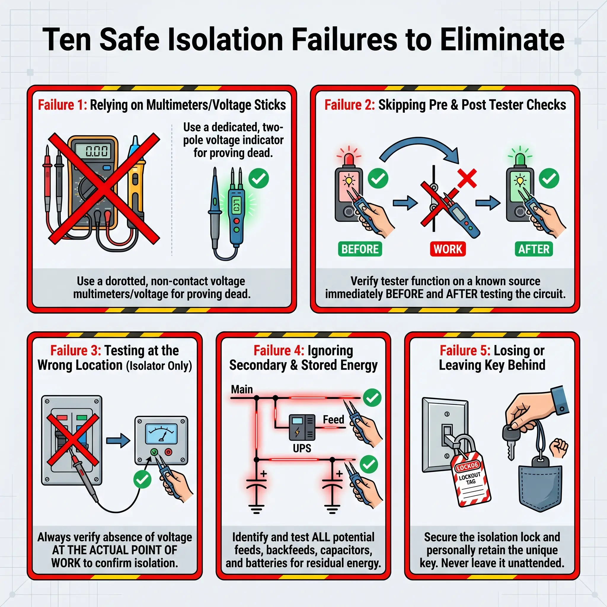
Common Mistakes and How to Avoid Them
The pattern of electrical incidents points to a small number of recurring failures — not to exotic hazards. Every item below appears repeatedly in published investigation summaries and enforcement notices across jurisdictions.
- Using a multimeter to prove dead. A multimeter set to the wrong range or with a failing battery can display 0 V across a live circuit. Use only a two-pole voltage indicator meeting BS EN 61243-3.
- Using a non-contact voltage stick to prove dead. These devices detect presence, not absence. They are live-finders, never dead-provers.
- Skipping the prove-the-tester step. Fatalities linked to failed instruments are almost always preceded by a skipped proving check.
- Isolating the wrong circuit from a mislabelled board. Particularly common in modified or extended installations where labelling has not been updated.
- Missing a secondary supply. UPS, generators, PV, and interconnected systems are the most frequently overlooked energy sources in investigation reports.
- Testing only at the isolator and not at the point of work. A borrowed neutral or cross-connection can live-feed a “dead” circuit downstream.
- Incomplete three-phase testing. Skipping neutral-to-earth or any phase-to-earth combinations leaves fault modes undetected.
- Handing the key to a colleague. The moment the key leaves the isolator’s pocket, the isolation is no longer personal.
- Relying on functional switching instead of an isolator. Contactors, emergency stops, and light switches do not provide isolation.
- Restoring supply without confirming workers clear. The reverse procedure is the second-most-common failure point after wrong-circuit isolation.
Each of these failures is preventable through disciplined application of the ten-step procedure and the reverse sequence. None requires additional equipment or additional time — only adherence.
Frequently Asked Questions
Getting Safe Isolation Right, Every Time
Safe isolation is the discipline that separates “switched off” from “safe to work on.” Four operational decisions govern every isolation: identify every source of supply before touching the isolator, use only GS38-compliant equipment proved immediately before and after the dead test, apply a personal lock that only leaves the isolator when the work is fully complete, and verify dead at the point of work with the full test matrix for single-phase or three-phase as applicable.
The legal and statistical case for the safe isolation procedure is unambiguous. Electrical fatalities persist year on year, OSHA Lockout/Tagout citations continue to rise, and the pattern of failure points to planning and verification gaps — not to unknown hazards. Every step in the procedure addresses a specific failure mode documented in the published investigation record. Skipping a step is not shortening the job; it is removing a barrier that another engineer placed there because someone died without it.
The ten-step safe isolation procedure, followed completely and reversed correctly, is the difference between a routine maintenance task and an entry in next year’s fatality statistics. It does not protect people because it is written down. It protects them because it is applied, in full, by a competent person, every single time.
Legal disclaimer: Regulatory content here reflects general HSE professional understanding of UK, US, Canadian, Australian, and international requirements as of April 2026. It is not legal advice. Specific compliance questions, enforcement situations, or prosecution risk should be directed to qualified legal counsel in the applicable jurisdiction.