
TL;DR — Myth vs Reality
- Myth: A jersey barrier is any plastic or concrete divider.
Reality: “Jersey barrier” is often used loosely, but profile, material, connection detail, and crash-test level matter. - Myth: Plastic jersey barriers are just lighter concrete barriers.
Reality: Water-filled units can be crashworthy only within specific tested conditions. Empty or underfilled units are channelizing devices, not positive protection. - Myth: The barrier itself is the safety system.
Reality: Barrier performance depends on tested configuration, deflection space, transitions, delineation, and crashworthy end treatment.
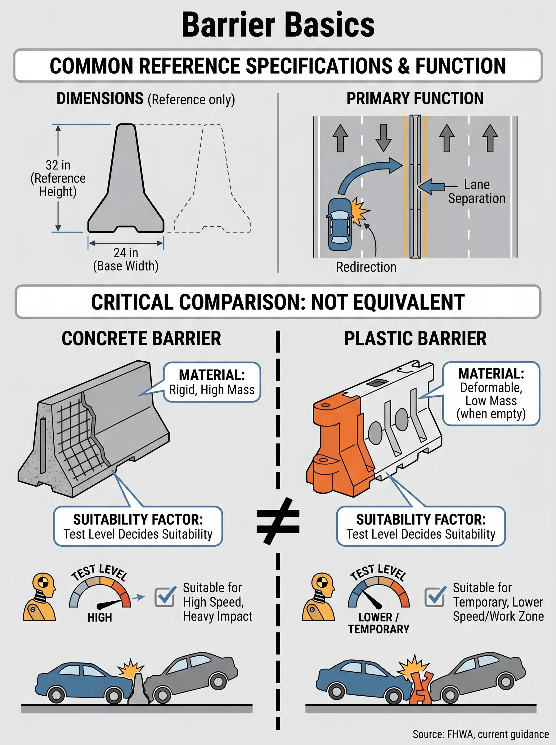
A jersey barrier is a modular concrete or jersey-style plastic barrier with a sloped safety-shape profile, commonly around 32 inches high, used to separate traffic, redirect errant vehicles, and protect workers or pedestrians in roadworks and other controlled environments. The term is widely used in practice, but concrete and plastic units are not crashworthiness equivalents.
In US work zones, the stakes are not academic. FHWA reported 899 work-zone fatalities in 2023, and National Safety Council summaries of BLS data show an average of 54 worker-pedestrians are killed each year after being struck by vehicles in work zones. That is why positive protection decisions sit firmly in the life-critical end of HSE planning.
This article explains what a jersey barrier is, how the safety shape works, which variants matter, where each type fits, and which US rules govern crashworthiness and deployment. I am using a US-first framework because the controlling standards are different in the UK, Canada, and other jurisdictions.
What Is a Jersey Barrier?
A jersey barrier is a modular barrier unit, usually precast concrete but sometimes plastic and water-ballasted, with a sloped face intended to separate lanes, reduce crossovers, channel traffic, and provide worker or pedestrian protection in controlled settings. In common site language, teams often use “jersey barrier” as a catch-all for any sloped traffic barrier. That shorthand causes specification mistakes.
The reference geometry most people recognize is the classic safety-shape barrier: about 32 inches tall, about 24 inches wide at the base, with a 3-inch vertical face at pavement level and slope changes above that. Current US barrier guidance distinguishes the Jersey profile from the F-shape, single-slope, and constant-slope families because their lift behavior, rollover tendency, and overlay tolerance differ.
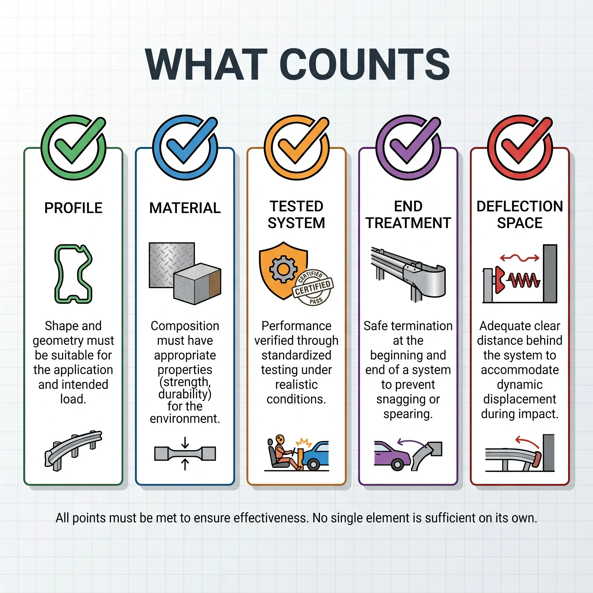
On site, this is the first misconception I correct: a “jersey barrier” is not a complete specification. A specification needs at least four things named clearly — profile, material, tested system, and deployment condition. Calling for “jersey barriers” without that detail is how teams end up buying channelization when they actually needed positive protection.
Jurisdiction Note: In California, “K-rail” is common terminology for temporary concrete traffic barriers. In practice, the term overlaps with Jersey- or F-shape barriers rather than describing a completely different safety concept.
How Does a Jersey Barrier Work?
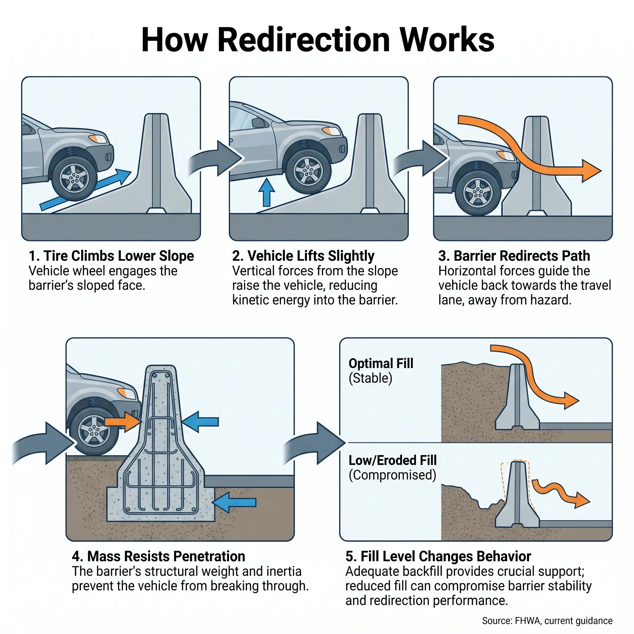
The safety-shape principle is simple to describe and easy to misuse. In a shallow-angle strike, the tire climbs the lower sloped face, the vehicle is lifted slightly, and the vehicle is redirected along the barrier instead of punching through it or crossing into opposing traffic. In higher-severity impacts, the barrier’s mass, geometry, and connection system resist penetration.
The classic Jersey and F-shape barriers both begin with a 3-inch vertical face, then transition to a lower sloped section. The Jersey break occurs at 13 inches, while the F-shape breaks at 10 inches. That lower break point is why the F-shape was developed to reduce rollover risk for smaller cars compared with the classic Jersey profile.
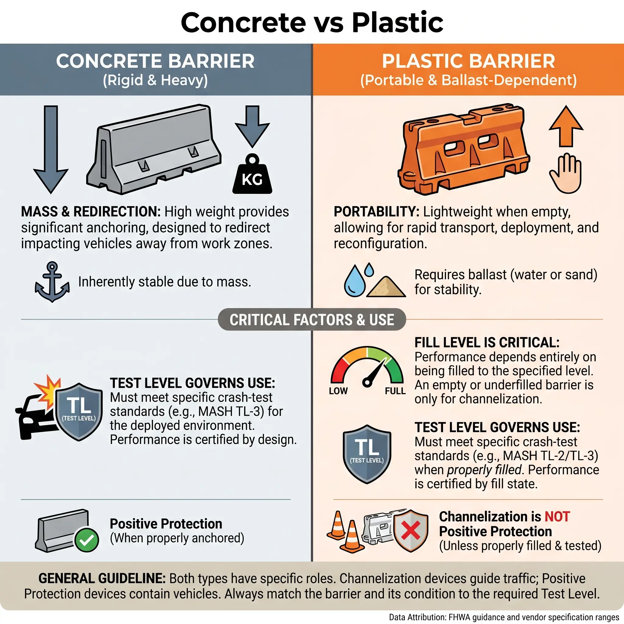
This is where material matters. Concrete barriers rely mainly on mass, rigidity, and tested connection behavior. Plastic water-filled barriers rely on ballast, shell deformation, displacement, and the exact fill condition used in the crash test. This is why water-filled barriers and channelizing devices that look similar should never be treated as interchangeable.
My standing field test is blunt: if a plastic unit has been drained for repositioning, is partly filled, or is connected differently from the tested setup, I do not treat it as positive protection. I treat it as suspect until the tested configuration is restored and verified. That distinction matters far more than the product brochure.
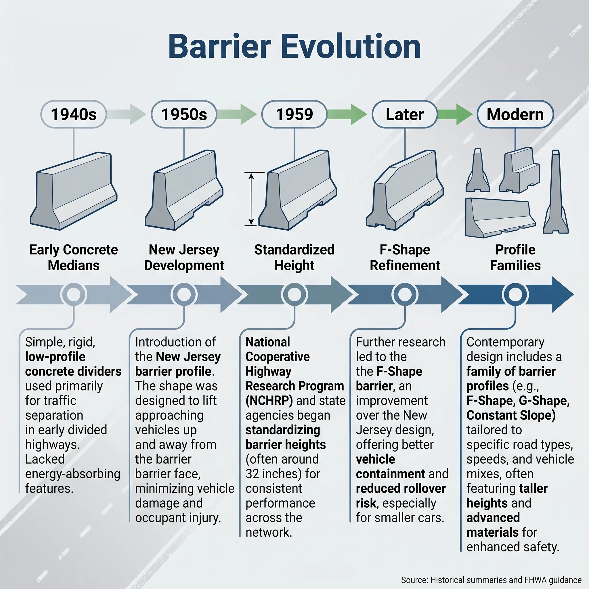
A Brief History: From New Jersey to a Family of Barrier Shapes
The jersey barrier is named for New Jersey, where the standardized form is commonly traced to development by the New Jersey State Highway Department with work associated with Stevens Institute of Technology in the 1950s. The familiar 32-inch profile is widely cited as having been introduced in 1959. Earlier concrete median barriers were already in use in California by the mid-1940s.
Barrier design then evolved rather than standing still. The Jersey shape is now treated as one member of a broader family that includes the F-shape, constant-slope, and single-slope profiles. Ontario’s taller wall systems addressed higher-containment needs, and the UK developed the concrete step barrier under a different standards structure.
History helps here only if it sharpens judgment. The lesson is not nostalgia. It is that barrier profile changed because crash performance learning changed.
Types of Jersey Barriers and Their Variants
Specifier decisions split across two axes: profile geometry and material. Treating those as the same choice is a common procurement error.
| Barrier type | Typical height | Key geometry point | Main strength | Main limitation | Typical use |
|---|---|---|---|---|---|
| Classic Jersey | 32 in | Slope break at 13 in | Proven safety-shape redirection | Higher small-car rollover tendency than F-shape | Legacy and existing systems |
| F-shape | 32 in family | Slope break at 10 in | Better small-car rollover performance | Still needs correct tested system and terminals | Newer installations |
| Constant-slope | 42 in | 10.8° from vertical | Overlay-tolerant; comparable to Jersey performance | Occupant force trade-offs differ | High-speed roads |
| Single-slope | 42 in family | 9.1° from vertical | Comparable to F-shape; low rollover tendency | Needs adequate height and tested details | High-speed highways |
| Ontario Tall Wall | 42 in | Taller containment wall | Better for high-COG vehicles, glare control | Heavier and more space-demanding | Higher-speed divided highways |
| Vertical wall | Varies | No safety-shape lift | Simple geometry | Highest occupant impact severity | Special cases only |
Current US guidance generally favors the F-shape or the 9.1-degree single-slope because the F-shape was developed to limit rollover potential and the single-slope reasonably mimics that performance. The constant-slope is treated as comparable to the Jersey shape, while the California single-slope is treated as comparable to the F-shape.
Concrete Jersey Barriers
Concrete remains the reference option for high-speed, high-consequence positive protection because it offers mass, lower deflection, durable connections, and compatibility with permanent or long-duration installations. Precast systems may use J-hooks, pin-and-loop, dowel, or other tested connectors. Those details are not accessories. They are part of the crashworthy system.
A standard 10-foot precast unit often falls in the 3,000 to 4,000 pound range in vendor catalogs, but that is not a universal regulatory value. It is best treated as a typical product range rather than a design assumption.
Plastic Water-Filled Jersey-Style Barriers
Plastic units are useful where portability, visibility, rapid deployment, and lower handling weight matter. They are common for lower-speed channelization, event perimeters, pedestrian routing, and some work zones where a product has been tested and accepted at the required level. But “plastic jersey barrier” is still not a safety conclusion. The test level, fill medium, fill percentage, connection detail, and permitted speed environment decide that.
The practical failure pattern is repeated drain-move-redeploy cycles. Units go back out partly filled, mismatched, or without the tested linkage. Once that happens, the crash-test pedigree no longer tells you much about the installation you actually have.
Watch For: A plastic unit that is visible enough to look protective can still be functioning as channelization only.
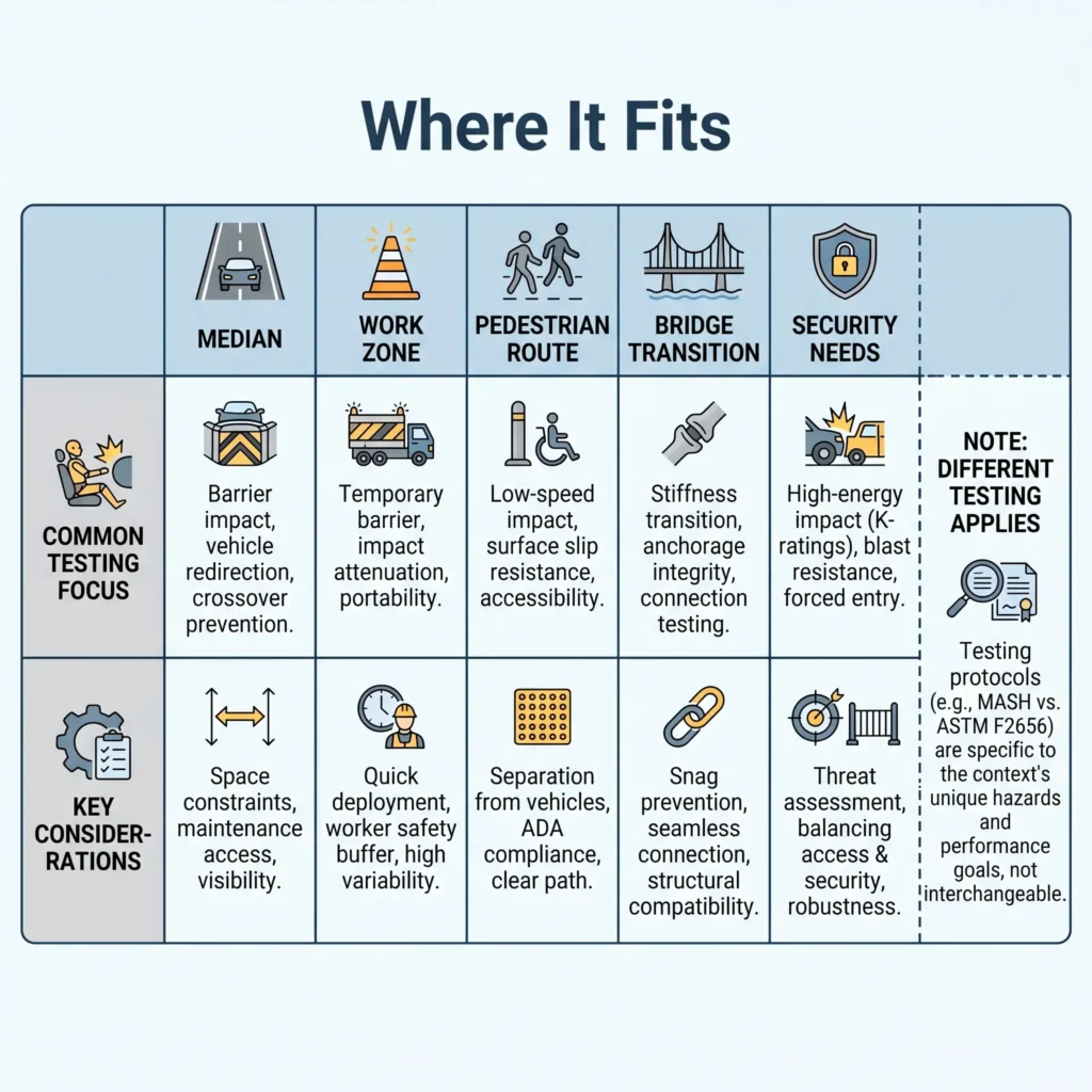
Where Jersey Barriers Are Used
Application setting does not decide the barrier alone, but it does frame the first judgment call.
- Highway medians: Permanent or long-duration concrete systems help prevent cross-median incursions and head-on conflicts.
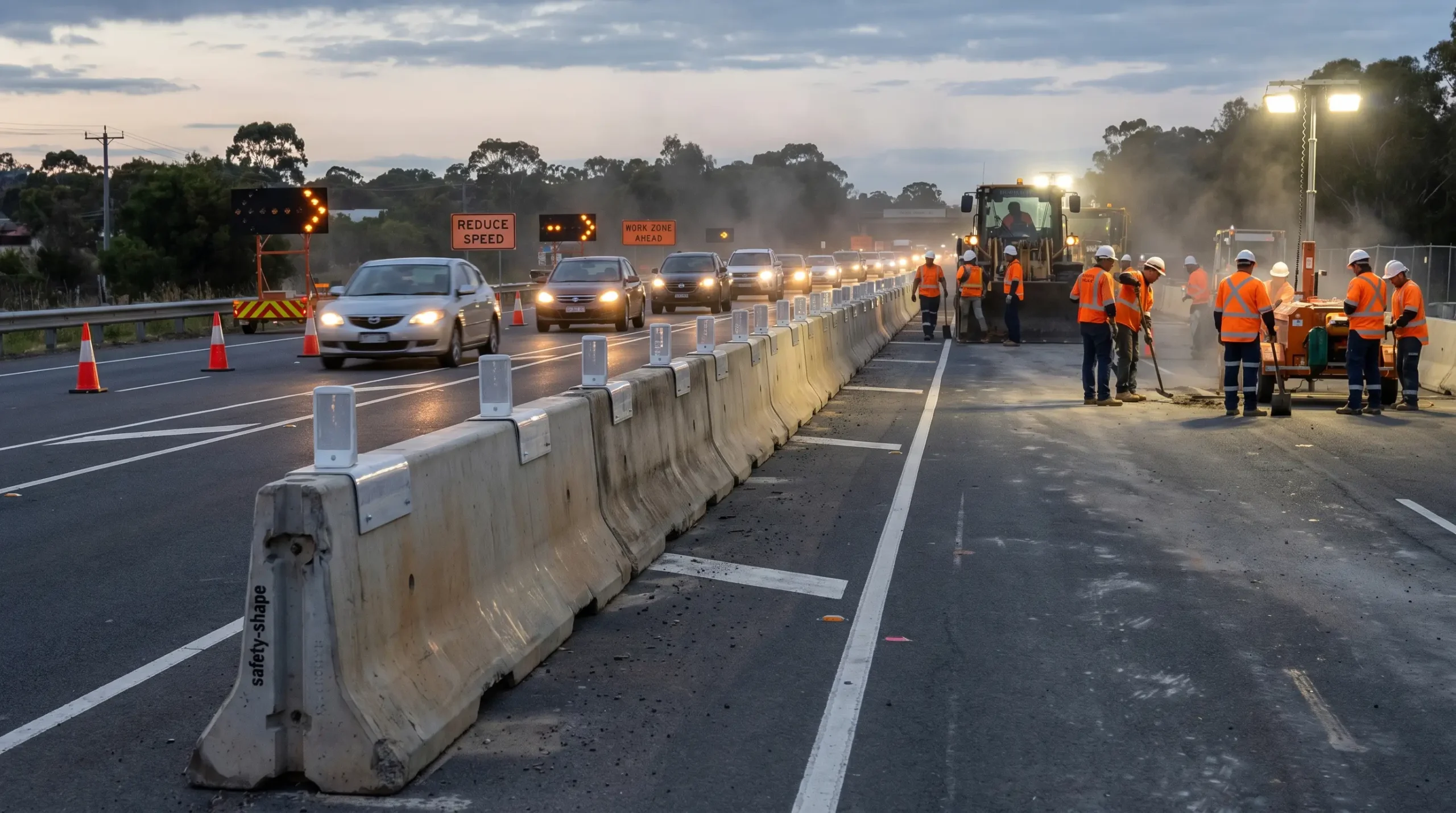
- Work zones and roadworks: Portable concrete or accepted water-filled systems can separate workers from live traffic when the setup matches the tested condition.
- Lane shifts, detours, and contraflow: Barriers create hard separation where cones and drums only guide behavior.
- Bridge work and parapet transitions: The barrier has to work with the transition, not stop at it.
- Pedestrian segregation in active TTC zones: Positive protection can separate people on foot from moving traffic where exposure is high.
- Parking and perimeter control: Lower-speed edge protection or channelization may justify lighter systems.
- Crowd control and event perimeters: Plastic units are common where portability matters more than high-containment performance.
- Security and anti-ram settings: Only when the barrier system is tested to security standards such as ASTM F2656, PAS 68, or IWA 14-1.
The mistake I see most often is selecting by use case label alone. “It’s a roadwork site” tells me almost nothing. I still need traffic speed, heavy-vehicle mix, worker exposure, available deflection space, and terminal treatment.
Safety Benefits of Jersey Barriers
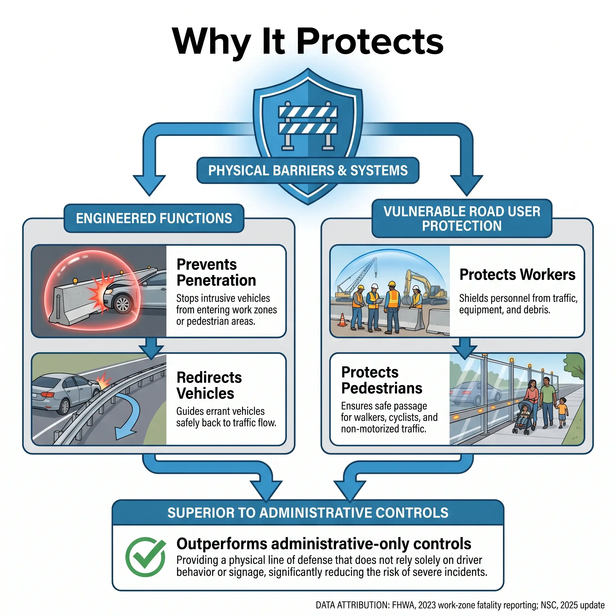
A jersey barrier earns its place because it is an engineering control, not because it looks substantial. In temporary traffic control, barriers are intended to help prevent vehicle penetration while minimizing injury to vehicle occupants and protecting workers, bicyclists, and pedestrians. That is positive protection language, and it matters.
Its first safety benefit is vehicle redirection. A properly selected and installed barrier can keep an errant vehicle out of the work space, opposing lane, or pedestrian route. That is a very different control outcome from warning signs, cones, or PPE, which depend on compliance after exposure already exists.
Its second benefit is worker protection in high-exposure TTC zones. Current guidance says longitudinal traffic barriers or other positive protection devices should be considered where workers are at increased risk from motorized traffic and the device offers the highest potential safety benefit. That aligns with struck-by fatality patterns in road construction.
Its third benefit is pedestrian separation. In urban roadworks, the barrier can turn a fragile taped walkway into a protected route. That matters when the hazard is not just impact but confusion, encroachment, and night-time visibility loss.
Its fourth benefit, in taller variants, is glare and higher-vehicle containment control. That is why height and profile cannot be treated as cosmetic choices. Different fleets produce different crash demands.
The Fix That Works: Treat the barrier as one control within the vehicle-worker interface hierarchy. It is only “higher-order” when the tested system, terminal, and space envelope are all present. Without that, the installation becomes theatre.
Regulatory and Crashworthiness Standards
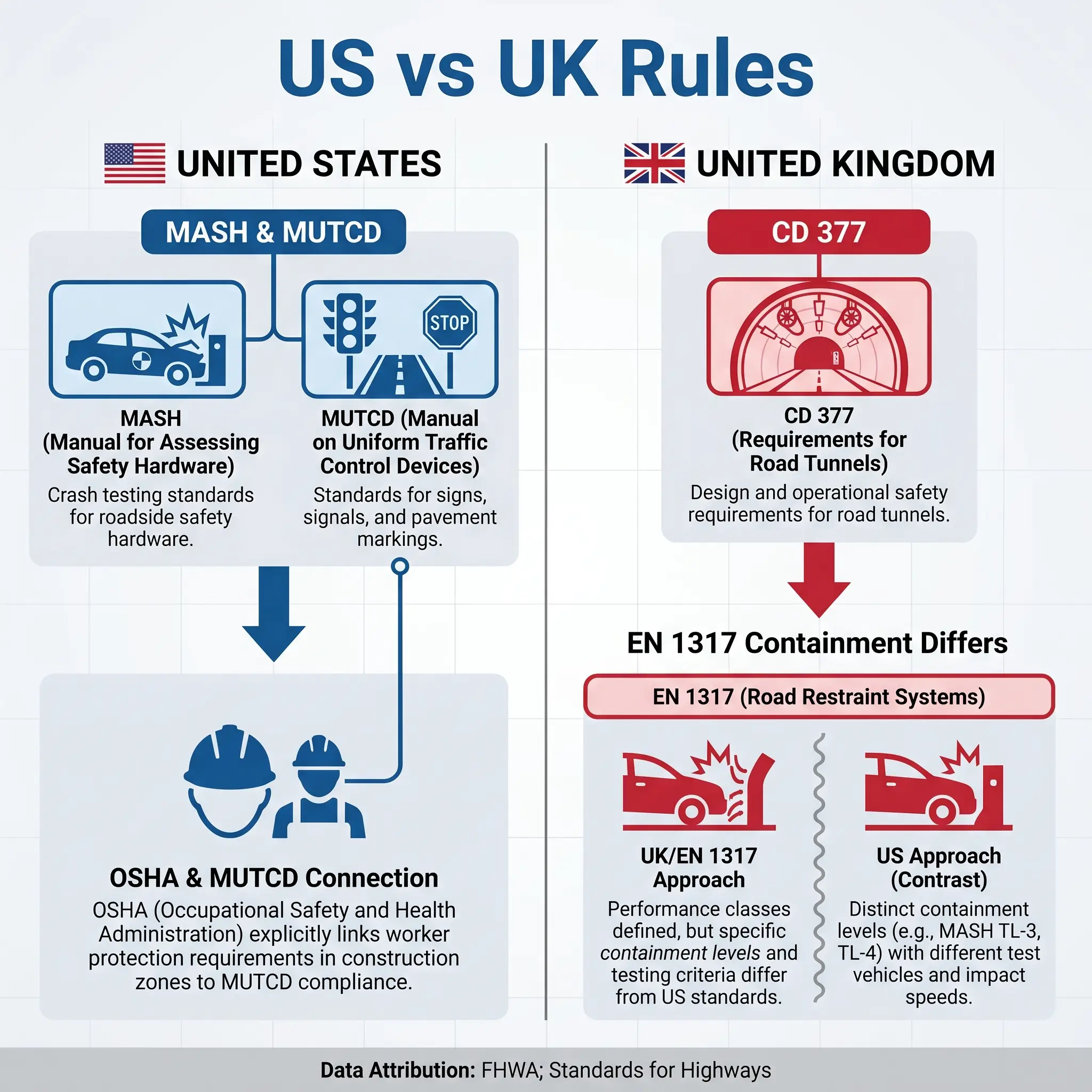
The regulatory framework below is primarily US-focused. Equivalent requirements in the UK, EU, Canada, and other jurisdictions use different test methods, containment levels, and clause numbering.
In the United States, three layers matter. FHWA and AASHTO govern crashworthiness expectations. MUTCD governs deployment in temporary traffic control. OSHA governs worker protection duties on construction sites. That hierarchy is where most vendor-style summaries go thin.
For crashworthiness, the controlling evaluation framework is AASHTO MASH, 2nd Edition (2016). Older NCHRP Report 350 hardware may still remain in service in some circumstances, but new products and modifications should not be assumed acceptable without current verification. Specifiers should confirm the current FHWA eligibility status of the exact product and test level before procurement.
For deployment, MUTCD 11th Edition Part 6 is the key temporary traffic control source. The December 2023 edition became effective on January 18, 2024, and states had until January 18, 2026 to adopt the national manual or a substantially conforming state version. Section 6M.02 defines temporary traffic barriers as positive protection devices and says they should be considered where workers face elevated traffic risk.
For OSHA, the live worker-protection requirement sits in 29 CFR 1926.200(g)(2). That section requires traffic control devices, including barricades and other protective devices used for construction workers, to conform to Part 6 of the MUTCD. Older secondary content often still points to 29 CFR 1926.202, but that standalone section was removed in 2019 as part of OSHA’s standards improvement update.
Freshness matters beyond MUTCD. FHWA’s updated Work Zone Safety and Mobility Rule and Temporary Traffic Control Devices Rule were both published on November 1, 2024 and became effective on December 2, 2024. These updates strengthened the framework around positive protection and temporary traffic control requirements on Federal-aid highway projects.
Outside the US, the UK uses DMRB CD 377 for road restraint system requirements, with barrier testing tied to EN 1317 rather than MASH. That is why “UK equivalent of a jersey barrier” is not a one-line translation exercise. The nearest functional equivalent is usually the concrete step barrier, but the governing framework is different.
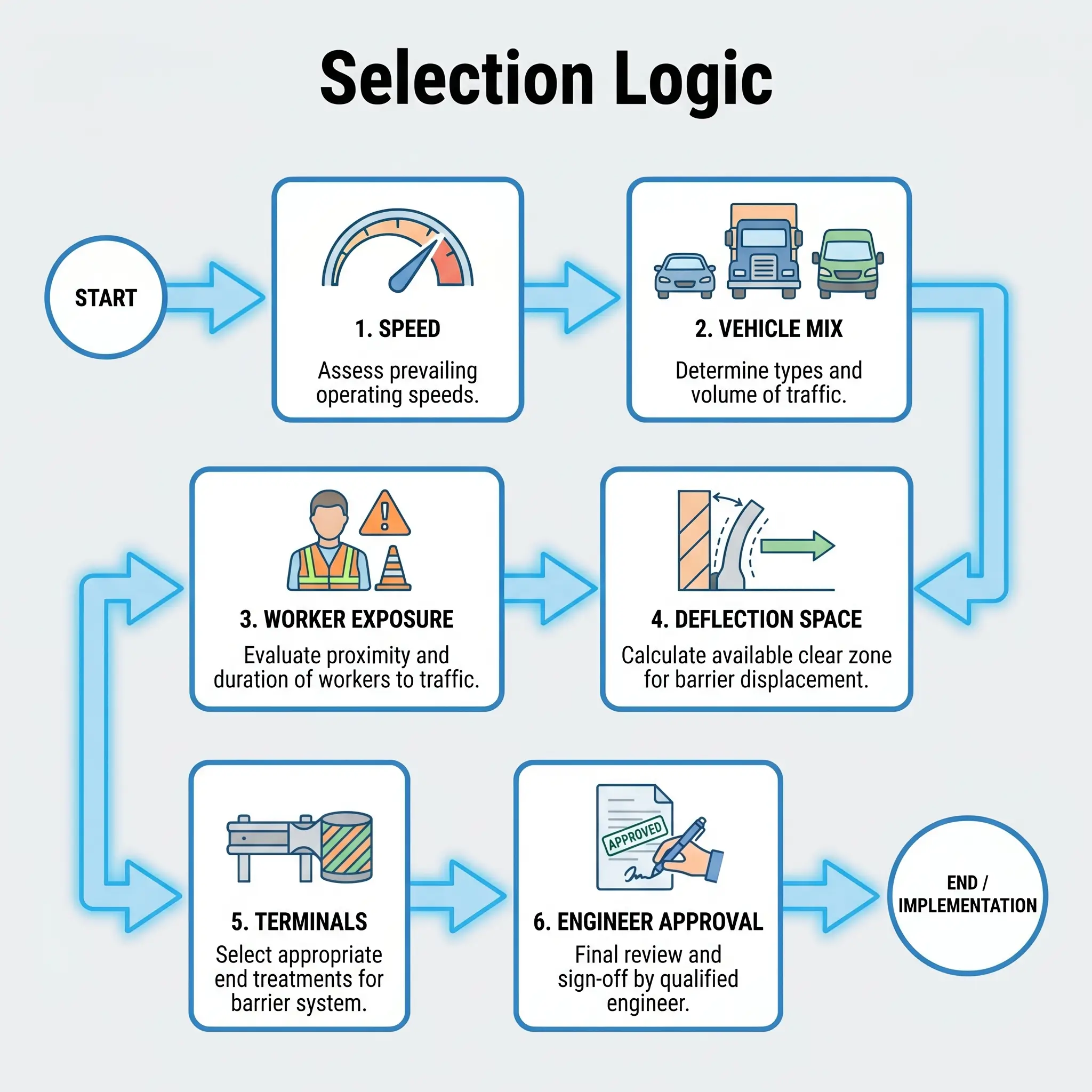
How to Select the Right Jersey Barrier
Selection is a hazard-control exercise, not a purchasing exercise.
- Traffic speed and operating environment: Higher speeds and more severe impact conditions drive the minimum acceptable test level.
- Vehicle mix: Heavy truck exposure can push you beyond the performance assumptions of lighter-duty systems.
- Worker exposure: If workers are on foot close to live traffic, the case for positive protection strengthens fast.
- Deflection space: A barrier can work in crash tests and still fail your site if it needs more lateral movement than the work space allows.
- Duration: Permanent and long-duration setups usually favor concrete. Short-duration or frequently shifting layouts may justify tested portable systems.
- Ends and transitions: The upstream end, downstream end, and any bridge-rail or guardrail transition are part of the hazard picture, not afterthoughts.
The recurring failure pattern is end-terminal neglect. Teams specify the barrier correctly, then leave a blunt end exposed or improvise a taper that was never crash rated. At that point, the barrier becomes the fixed-object hazard.
Audit Point: Jersey barrier selection, placement, anchoring, and end-terminal design must be performed or approved by a qualified engineer or competent traffic-control designer. This article is educational and does not replace project-specific engineering judgment.
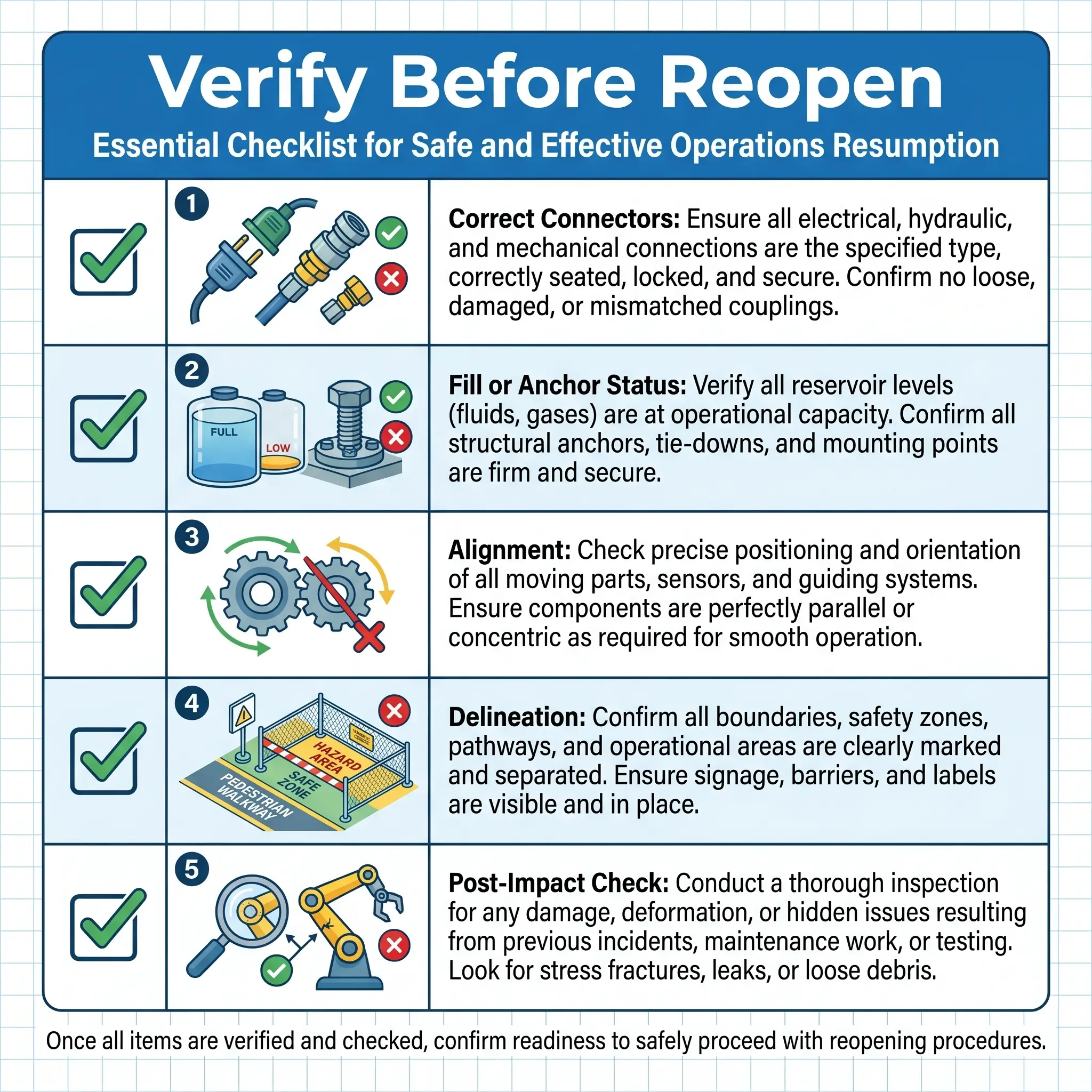
Installation, Anchoring, and Maintenance Considerations
Good barrier choices are often weakened in installation. Crashworthy hardware must be installed in the tested configuration, with the tested connection system, on the intended support surface, and with the intended ballast or anchorage detail. Mixing manufacturers, swapping pins, omitting connectors, or changing fill condition can break the basis of acceptance.
Temporary traffic barriers also need supplementary delineation, pavement markings, or channelizing devices. A concrete wall without adequate delineation is not a finished control. It is an impact hazard that drivers may see too late.
Daily verification should include alignment, gaps, damaged faces, displaced units, reflectivity or delineation condition, and evidence of impact. Any struck barrier that has moved, cracked materially, or lost connection integrity should be assessed before reopening to traffic. For precast units moved repeatedly across phases, I also watch lifting points and hardware for spalling, distortion, or cumulative wear. That repositioning degradation is easy to miss until a unit is near retirement.
A separate worker-risk issue sits in handling. Concrete units are crushing hazards during lifting and set-down. Use only the manufacturer’s specified pick points and handling method.
Competent-person caveat: Installation, relocation, anchoring, inspection, and post-impact release back into service should be controlled by competent personnel and approved where required by the project designer or engineer.
Frequently Asked Questions
A jersey barrier is easy to recognize and easy to oversimplify. The useful definition is not “that concrete divider on the road.” It is a crash-tested separation system whose safety value depends on profile, material, tested configuration, terminal treatment, and the exposure it is meant to control.
For HSE teams, the practical takeaway is this: stop asking only what the barrier is called. Ask what hazard it is meant to control, what test level the site demands, how much deflection space exists, and whether the installed system still matches the tested one. That is the difference between positive protection and false reassurance.