
TL;DR
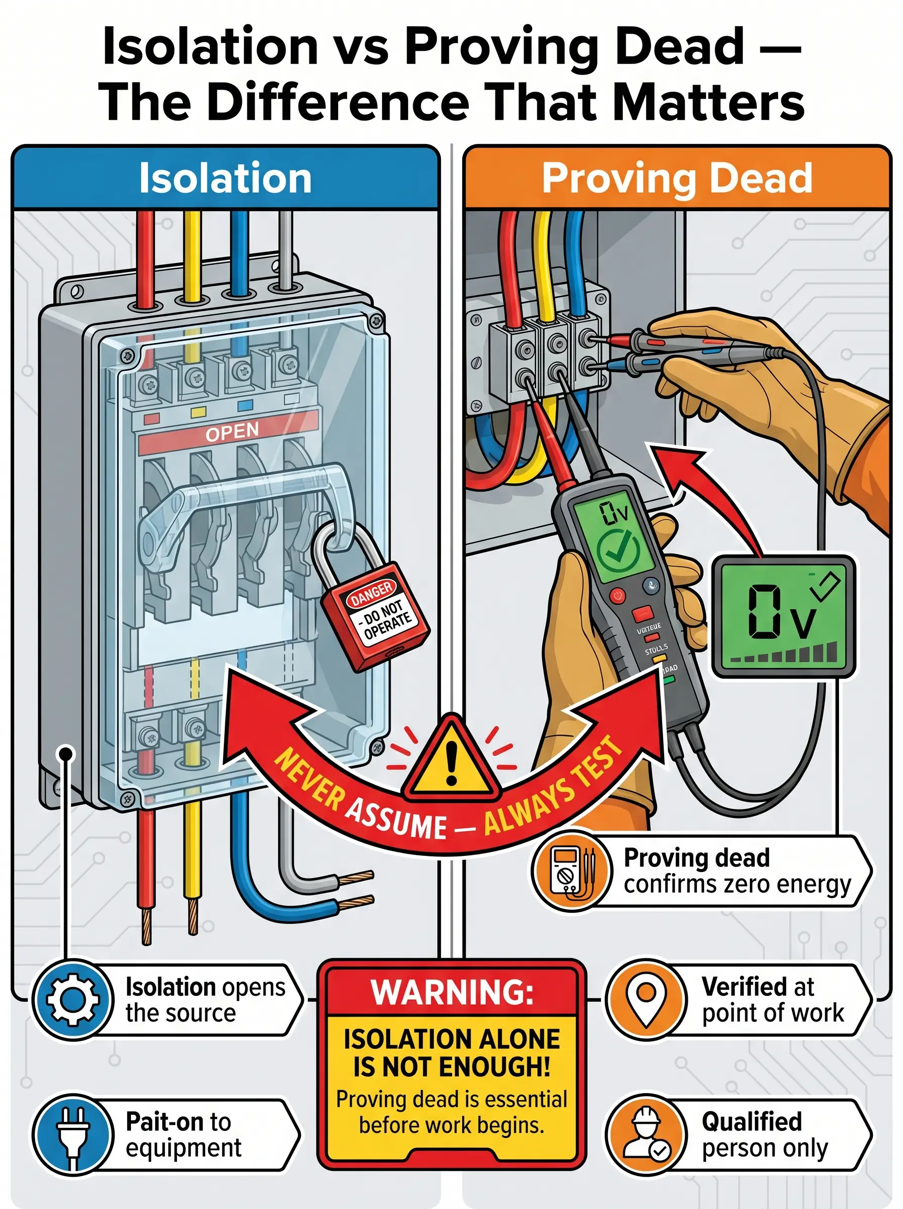
- Isolation and proving dead are not the same act. Opening a disconnector deenergises the source; proving dead verifies zero voltage at the point of work, at the moment of work.
- Use a purpose-built two-pole voltage indicator, never a multimeter. BS EN 61243-3 detectors (UK) and adequately rated portable instruments under NFPA 70E 120.6(7) (US) are the only defensible tools.
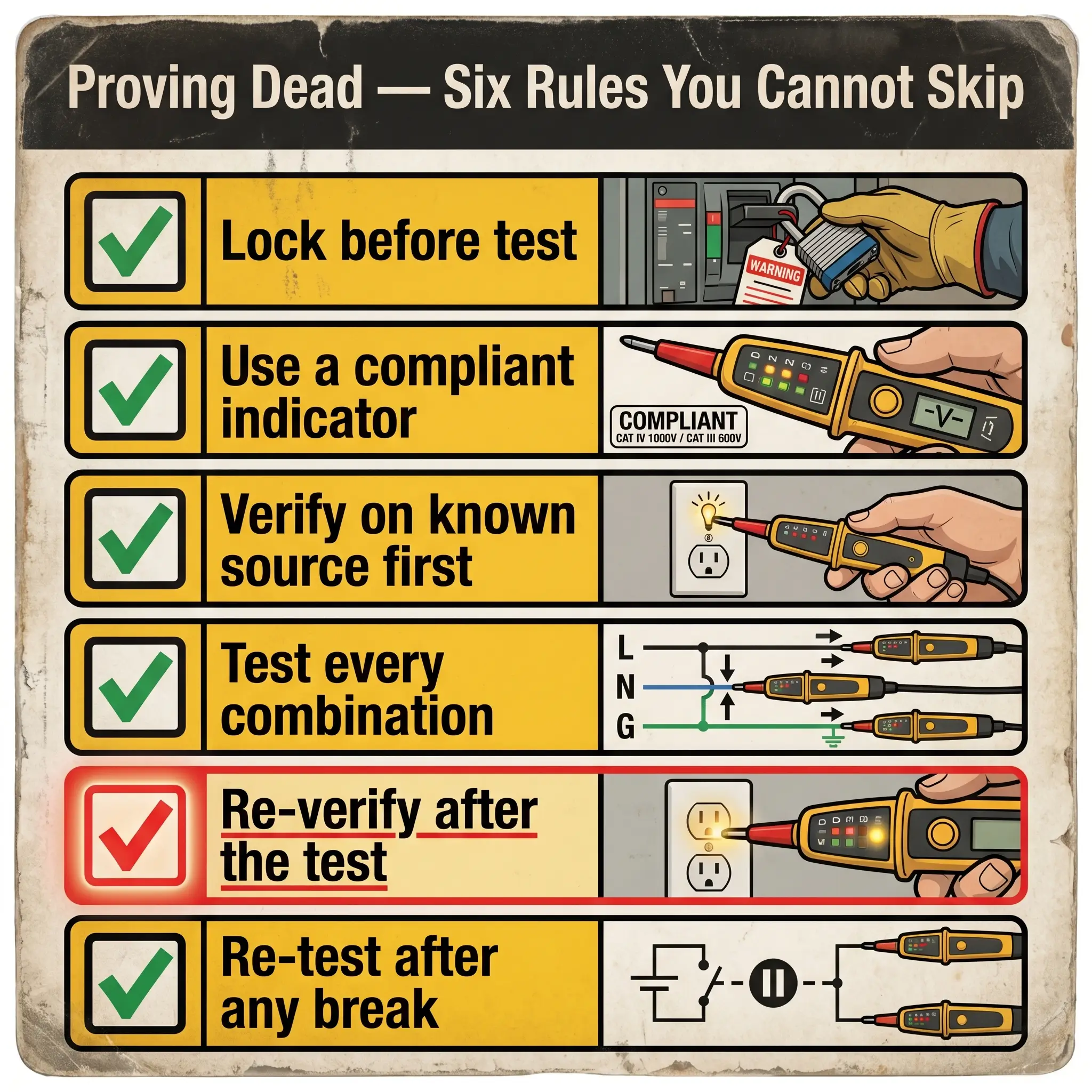
- Always perform live–dead–live. Verify the indicator on a known live source immediately before and immediately after the test — a tester that failed mid-sequence reads zero on live conductors.
- Test every combination the system demands. Single-phase requires three tests; three-phase requires ten, including neutral-to-earth.
- Treat every unexpected reading as real until proven otherwise. Phantom voltage collapses under a low-impedance load; backfeed does not.
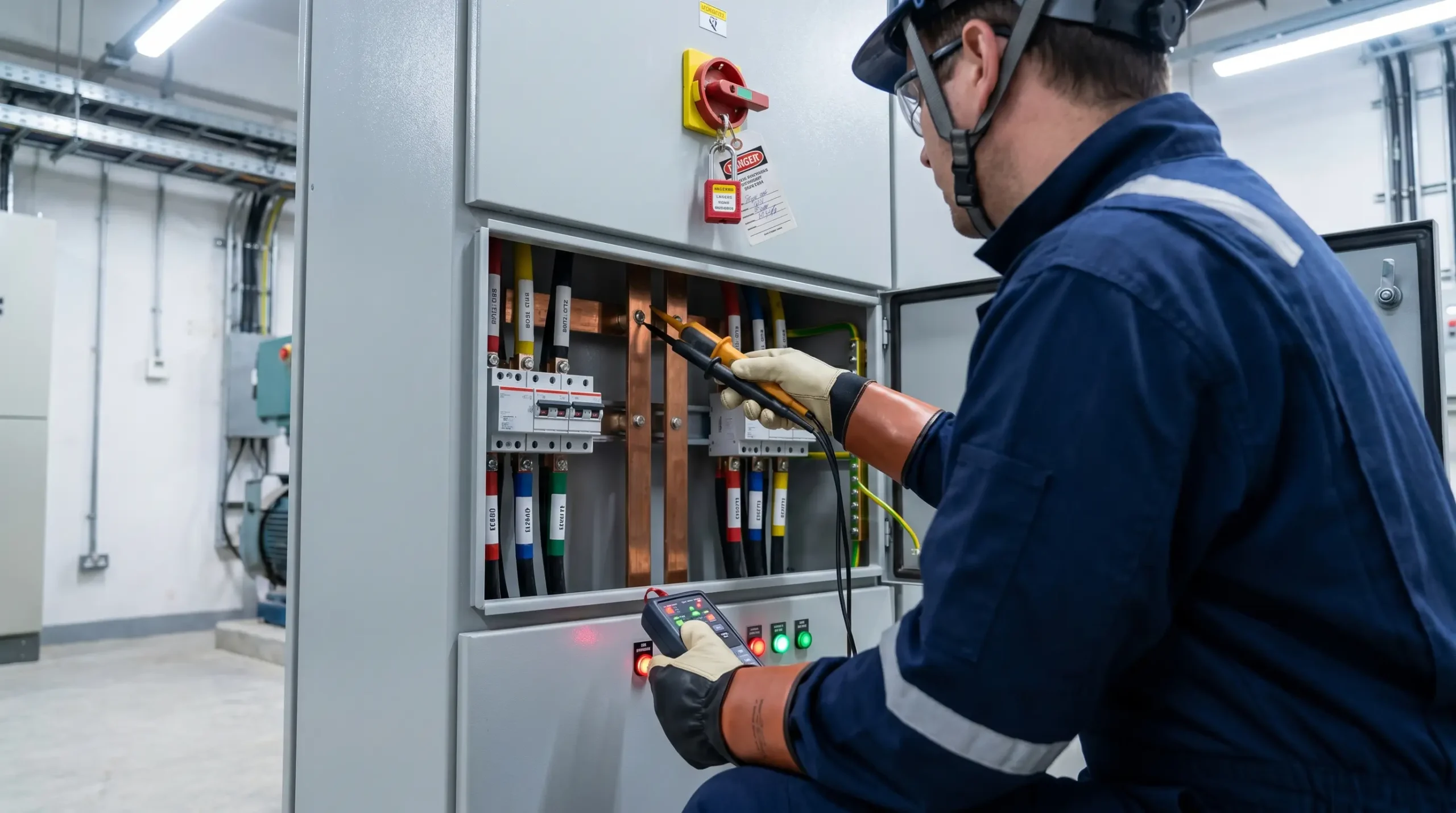
Proving dead is the final verification step in an electrical isolation sequence, performed by a qualified person at the point of work using a purpose-built voltage indicator that has been tested on a known live source both immediately before and immediately after the circuit test. Isolation opens the source; proving dead confirms zero energy.
A Circuit Is Not Dead Because Someone Switched It Off
A circuit is not dead because a breaker is open. It is not dead because someone said it was off, or because the lights went out when the handle was thrown, or because the panel schedule says so. A circuit is dead only when a qualified person has tested it at the point of work, with equipment fit for the job, using a sequence that accounts for the possibility that the tester itself has failed during the test.
That gap — between “switched off” and “verified dead” — is where most fatal electrical contact during maintenance happens. US workplace data recorded 1,940 electrical fatalities between 2011 and 2023 (Electrical Safety Foundation International, 2025), and 74% of those deaths occurred in non-electrical occupations (Electrical Safety Foundation International, 2025) — workers who assumed the circuit had been made safe by someone else. This article walks through what proving dead means under OSHA, HSE, and EN rules, what equipment satisfies each jurisdiction, the verify-test-verify sequence that catches tester failure, the decision logic for anomalous readings, and the stored-energy hazards that still kill people on circuits where the AC supply is genuinely open.
Competent-Person Caveat This article is educational. Proving dead is life-critical work that must be planned, authorised, and performed only by a qualified person as defined under OSHA 29 CFR 1910.333, a competent person under the Electricity at Work Regulations 1989 (UK), or a skilled person under EN 50110-1:2023 — with jurisdiction-specific training, written employer procedures, and site-specific risk assessment. The information here does not confer competence.
Jurisdiction Note Regulatory content in this article reflects the author’s professional understanding of US (OSHA, NFPA 70E), UK (HSE, EAWR, BS EN) and EU (EN 50110-1) requirements as of April 2026. It is not legal advice. Enforcement questions, prosecution risk, or site-specific interpretation should be directed to qualified legal counsel in the applicable jurisdiction.
What “Proving Dead” Actually Means — and Why It Is Not the Same as Isolation
Proving dead is the final verification step in a safe isolation sequence, performed by a qualified person at the point of work, with compliant test equipment, to confirm that no hazardous voltage is present on the conductors about to be touched. It is a test of state at a single moment in time — it tells you the conductor is dead now. It does not prevent re-energisation; that is the function of the lock and tag applied earlier in the sequence.
The regulatory distinction between “deenergised” and “dead” is explicit on both sides of the Atlantic. OSHA 1910.333(b)(2)(iv)(B) (US, General Industry) requires a qualified person to use test equipment to verify conductors are deenergised and to determine whether any energised condition exists from induced voltage or backfeed — a legal separation between opening the source and proving the circuit. EN 50110-1:2023 (EU) does the same through rule 3 of its five safety rules, the “verify absence of operating voltage” step that sits between securing against reconnection and earthing.
The reason the procedure exists is not bureaucratic. It exists because panel schedules are wrong, breakers are mislabelled, neutrals are shared between circuits, standby generators start on mains loss, photovoltaic arrays remain live while illuminated, and control-power transformers feed backward through interlocks no-one documented. The pattern that appears with depressing consistency in published OSHA fatality summaries and HSE prosecution narratives under EAWR Reg. 14 uses the same three words of investigator testimony: I thought it was off.
Where Proving Dead Fits in the Full Safe Isolation Sequence
Proving dead sits inside a longer sequence, and skipping the earlier steps while performing the test offers no protection at all. Under EN 50110-1:2023 clause 6.2 (EU) the five safety rules run in fixed order: disconnect completely; secure against reconnection; verify absence of operating voltage; earth and short-circuit; protect adjacent live parts. Verification is step 3 — after the lock, not before. The same logic appears in NFPA 70E 120.6 (US consensus) where absence-of-voltage testing is step 7 of an eight-step process, and in OSHA 29 CFR 1910.333(b)(2) where the test requirement is paragraph (iv)(B), sitting after the lock/tag paragraph (iii).
Read across jurisdictions, the core sequence is identical in substance. Only the names differ.
| OSHA 29 CFR 1910.333(b)(2) | NFPA 70E 120.6 | EN 50110-1:2023 |
|---|---|---|
| Determine and disconnect all sources (i) | Steps 1–4: identify sources, open disconnect | Rule 1: Disconnect completely |
| Lock and tag (iii) | Step 5: apply lock/tag | Rule 2: Secure against reconnection |
| Verify deenergised condition (iv)(B) | Step 7: test for absence of voltage | Rule 3: Verify absence of operating voltage |
| Treat as energised until verified (iv)(A) | Step 8: ground where required | Rules 4–5: Earth and protect adjacent live parts |
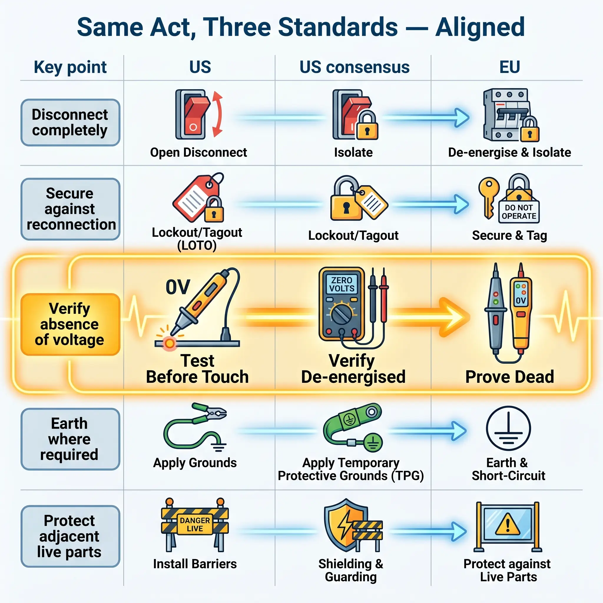
A practical reading of this alignment: the only correct order is lock-then-test. Testing before locking the isolation device provides no protection if someone closes the breaker during the test.
The Test Equipment: What Is Acceptable, What Is Not, and Why
Most proving-dead errors begin with the instrument. Two non-negotiables cut across jurisdictions: the tester must be purpose-built for voltage detection, and it must be adequately rated for the installation category and fault energy at the point of use.
In UK practice, HSE Guidance Note GS38 (4th edition, 2015) is the operational reference. It specifies two-pole voltage indicators conforming to BS EN 61243-3:2014, exposed probe tips of 4 mm maximum (2 mm preferred with shrouds), finger guards on the probes, and leads marked with CAT rating and manufacturer. GS38 explicitly advises against multimeters for proving dead — wrong-range selection is easy, battery failure is undetectable until the display goes blank, and in current or resistance modes a multimeter applied across live conductors can draw destructive fault current and explode the instrument in the tester’s hand.
In US practice, NFPA 70E 120.6(7) (2024 edition) requires an adequately rated portable test instrument and verification on a known source before and after use. OSHA 29 CFR 1910.334 applies the same “adequately rated” standard to test equipment generally. The US standards do not name specific product types, but the practical interpretation across industrial maintenance and by the manufacturers authoring compliance guidance is the same as the UK position: a multimeter in volts mode is not the right tool for the job.
The installation category matters as much as the voltage rating. Under BS EN 61010-1 (UK/EU, 2010 with A1:2019), CAT II is for appliance-level circuits, CAT III for fixed distribution and branch circuits, and CAT IV for the origin of the installation and utility source. For most LV maintenance at panel or distribution-board level, CAT III is the minimum and CAT IV is the safer default.
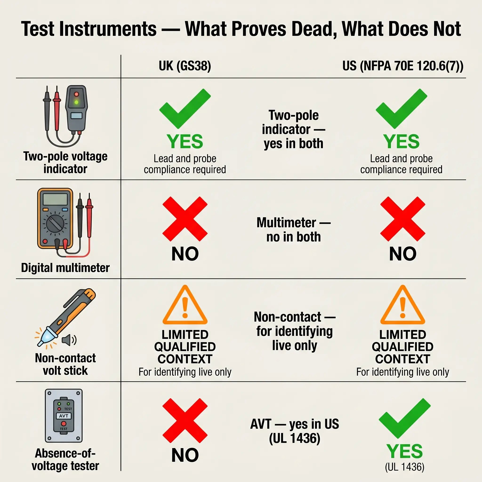
Three equipment questions come up constantly, and each has a clear answer:
| Equipment type | Acceptable for proving dead? | Governing reference |
|---|---|---|
| Two-pole voltage indicator (BS EN 61243-3) | Yes — UK and US | GS38 (UK); NFPA 70E 120.6(7) (US) |
| Digital multimeter | No — not purpose-built | GS38 explicit; NFPA 70E by interpretation |
| Non-contact “volt stick” | No — use only to identify live | GS38 explicit; NFPA 70E 120.6(7) Exception 2 (LV) |
| Permanently-mounted AVT (UL 1436 listed) | Yes — US only | NFPA 70E 120.6(7) Exception No. 1 |
One pattern worth naming: a fully compliant tester body is often paired with non-compliant leads scavenged from a broken multimeter. The instrument body passing GS38 does not make the kit GS38-compliant. Probes, leads, and clips must all meet the standard — and on an audit, that is routinely where the finding gets written.
The 2018 introduction of NFPA 70E 120.6(7) Exception No. 1 — permitting permanently-mounted absence-of-voltage testers listed to UL 1436 — recognises a practical reality: opening an enclosure to access test points is itself an arc-flash exposure. An AVT that tests through closed-door operation reduces that exposure without removing the verification requirement. The exception applies only to listed and labelled devices; a generic indicator wired into a panel does not qualify.
The Verify–Test–Verify Procedure, Step by Step
The procedural heart of proving dead is a fixed sequence that catches both the obvious hazard — the circuit was not actually isolated — and the subtler hazard: the tester failed during the test. The steps below integrate the requirements of OSHA 1910.333(b)(2), NFPA 70E 120.6, HSE GS38, and EN 50110-1 into a single defensible workflow. They do not replace site-specific written procedures, which take precedence.
- Confirm permission to isolate. Check for life-safety systems, process-critical loads, shared supplies, and anyone else working on the same circuit or equipment downstream.
- Identify every source of supply. Mains feed, standby generators, UPS outputs, photovoltaic inverters, battery systems, capacitor banks, control-power transformers — anything that could energise the conductor from an unexpected direction.
- Open the disconnecting means at the correct point. OSHA 1910.333(b)(2)(ii) is explicit: control switches, push-buttons, and interlocks are not isolation devices.
- Apply lock and tag. Key held by the person doing the work, or a group-lockout hasp for multi-worker jobs. One person, one lock, one key is the default.
- Attempt operation to confirm isolation. The “try” of lock-tag-try — press start, operate local controls, confirm the equipment does not run.
- Release stored energy. Discharge capacitors through manufacturer-specified bleed resistors, allow PFC units to self-discharge, confirm inductive loads have collapsed.
- Select the right instrument. A GS38-compliant voltage indicator (UK) or adequately rated portable test instrument (US), matched to the installation category and voltage class.
- Verify the indicator on a known live source. A proving unit is preferred over a random live socket — it exercises every LED on every range.
- Test at the point of work, across every combination. See the test-combination matrix below.
- Re-verify the indicator on the same known source. This is the step most often skipped. A tester that failed during the test will display 0 V on a live conductor; only the post-test verification reveals the failure.
- Record the result. If site procedure or permit-to-work requires documentation, complete it before starting work.
- Re-test before restarting after any break. If the worksite is left unattended — lunch, shift change, overnight — the verification is no longer current.
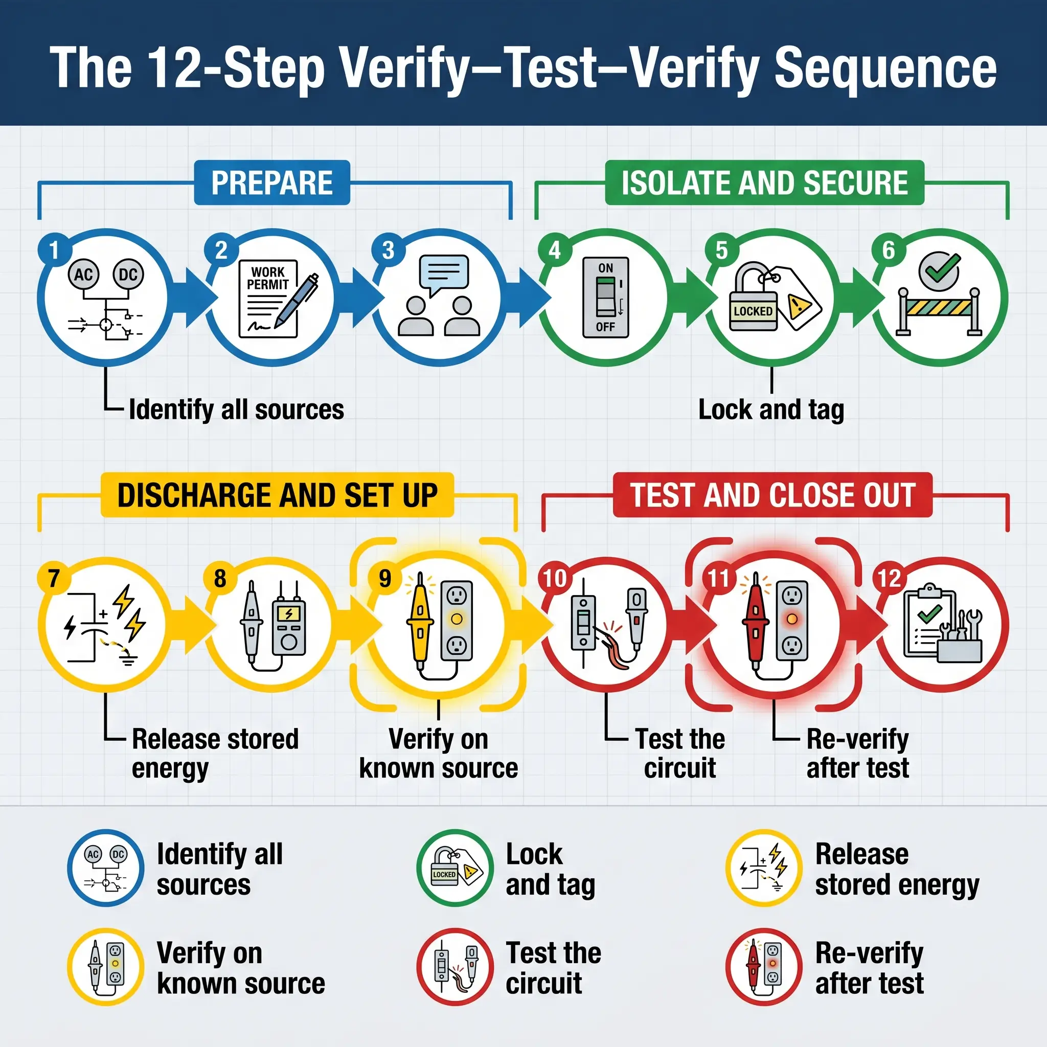
The post-test re-verification (step 10) is worth dwelling on. In published practitioner writing and investigation narratives, this is the step most often treated as bureaucratic duplication. It is the opposite. It is the only way to distinguish between a circuit that is genuinely dead and a tester that has died during the test. Teams that skip it have removed the discipline’s principal protection against instrument failure.
What Test Combinations to Make on Single-Phase and Three-Phase Systems
A single voltage reading between two points does not prove the whole circuit dead. NFPA 70E 120.6(7) (US) requires each phase conductor to be tested both phase-to-phase and phase-to-ground — a rule that translates to a minimum number of tests depending on the system type.
| System | Tests required | What each combination catches |
|---|---|---|
| Single-phase | 3 tests: L–N, L–E, N–E | Live phase, phase-earth fault, borrowed or lost neutral |
| Three-phase (ten-point) | L1–L2, L1–L3, L2–L3, L1–N, L2–N, L3–N, L1–E, L2–E, L3–E, N–E | Any phase live, any phase-earth fault, lost PEN, N–E fault |
The neutral-to-earth test matters more than most procedures acknowledge. On a TN-C-S (PME) installation, a lost PEN can leave the entire neutral system raised to phase voltage relative to true earth — a fatal condition that a simple L–N test will not reveal, because neutral and earth appear to agree with each other while both are elevated. The N–E check against a local earth reference catches it.
When the Reading Is Not Clean: Phantom, Induced, and Backfed Voltage
Most procedures end with a clean binary: zero volts means work, anything else means live. Real installations rarely cooperate. A qualified person meeting the discipline’s standard needs to know the difference between a harmless coupling artefact and a genuine second energy source — because the consequence of misdiagnosis is direct contact with a live conductor believed to be safe.
Three phenomena commonly produce unexpected readings on an isolated circuit:
- Phantom (ghost) voltage is capacitive coupling from a parallel energised conductor, typically producing 40–80 V to ground on a high-impedance digital multimeter. It collapses to near zero under a low-impedance test load. It is not a hazardous source.
- Induced voltage is inductive coupling from long parallel runs or nearby high-current feeders. It behaves similarly to phantom under a low-impedance test but can rise with load on the adjacent energised circuit, and on long cable runs it can deliver enough current to produce a painful shock.
- Backfed voltage is a real energy source feeding the “isolated” conductor through an unexpected path: a control-power transformer, a running generator, a UPS output, a photovoltaic inverter, a shared-neutral multi-wire branch circuit, or a mislabelled interlock. It does not collapse under a low-impedance test.
Watch For A “shouldn’t be there” reading is never a final diagnosis. The decision rule is straightforward: if the voltage persists under a low-impedance test, treat the conductor as energised until the source and path are identified and opened. Treating unexpected voltage as innocent until proved guilty is the inverted risk posture of this entire discipline.
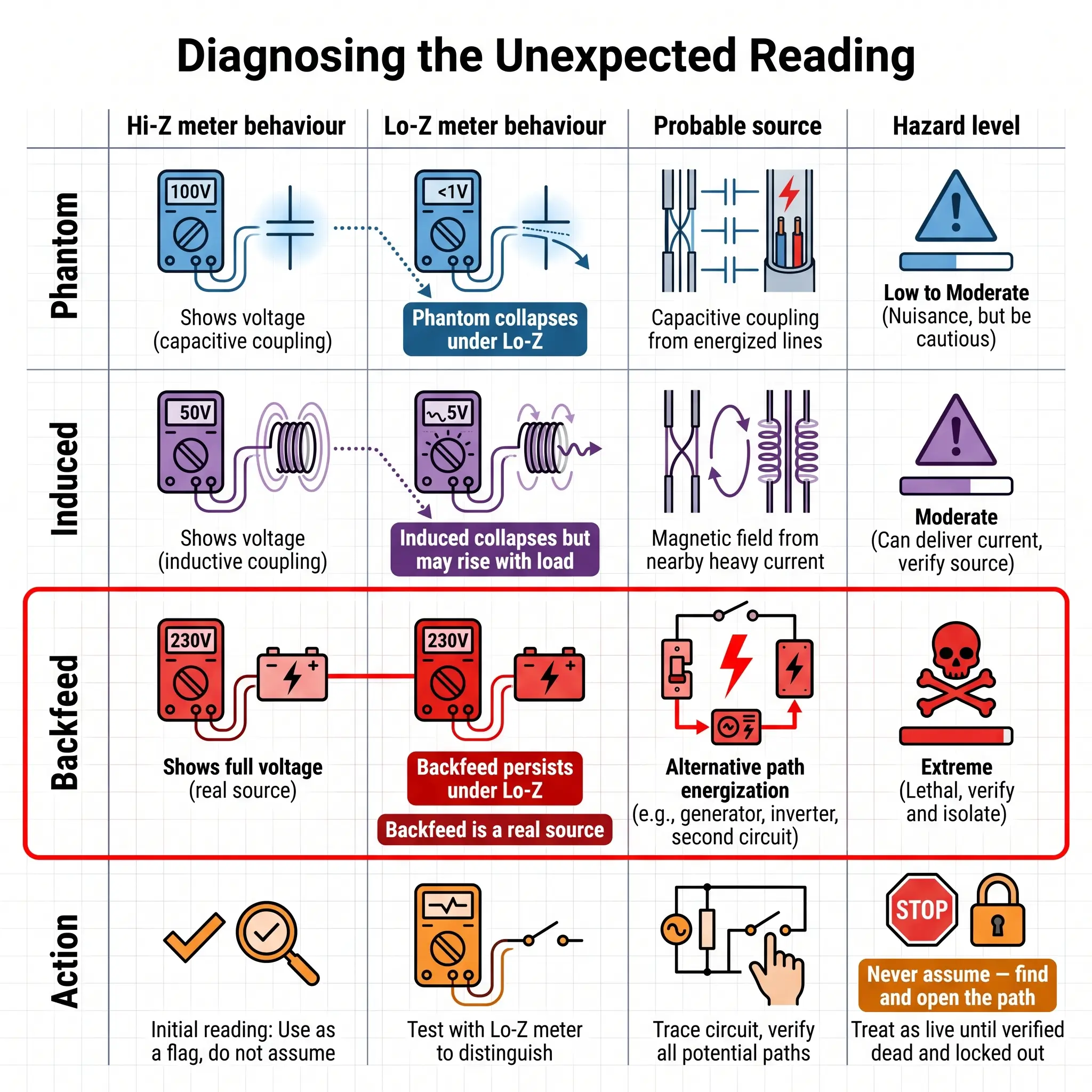
The instrument choice matters here too. A dedicated two-pole voltage indicator has low input impedance by design, so it is far less susceptible to phantom readings than a 10 MΩ digital multimeter — which is one of several reasons GS38 prefers the purpose-built indicator even though a DMM can technically display volts. On harmonic-rich circuits feeding variable-frequency drives, a true-RMS instrument is required to read accurately. Above 1,000 V, NFPA 70E 120.6(7) Exception No. 2 permits capacitive proximity testers on medium-voltage systems, recognising that direct-contact testing at those voltages creates its own hazards.
DC Systems, Capacitors, and Stored Energy
Most proving-dead content is written for AC distribution and stops at the point the AC source is open. That assumption falls apart on DC systems, energy storage, and capacitor-heavy equipment — where the real hazard can persist for minutes or hours after the supply is disconnected.
Capacitors hold lethal charge. DC-link capacitors inside variable-frequency drives, uninterruptible power supplies, and power-factor correction banks can store enough energy to cause electrocution or serious arc-flash burns well after the AC supply is open. The correct discharge route is always the manufacturer-specified procedure — typically a bleed resistor of defined rating and duration — followed by verification with a DC-capable voltage indicator at the capacitor terminals. Shorting a capacitor with a screwdriver is not a discharge method; it is a method of producing shrapnel.
Photovoltaic arrays stay live whenever illuminated. Opening the AC disconnect at the inverter does not deenergise the DC side. Module-level isolation, array covering, or rapid-shutdown systems compliant with the local authority having jurisdiction are required before the DC conductors can be treated as dead. Battery energy storage and telecom DC plants have no “off” position at all — the battery is always a source, and isolation requires physical disconnection followed by verification at the point of work.
A forward signal worth tracking: the forthcoming 2027 edition of NFPA 70E is introducing a new exception at 120.6(7) recognising that on current-regulated circuits — the canonical example is airfield lighting series loops — absence of voltage is not by itself sufficient, and absence of current must also be confirmed (Brainfiller, 2025). This is the first time the US consensus standard has formally acknowledged that the long-standing “test for zero volts” rule has a blind spot on certain circuit topologies.
What the Law Actually Requires: OSHA, HSE, and EU Duty Holders
Sites cited for electrical-isolation failures tend to show the same three patterns: no compliant test equipment available, no written procedure that integrates the verify step, and no demonstration that the qualified person had been trained specifically to use what was provided. The legal obligations that underpin those findings sit in four documents across three jurisdictions.
Under US law, the requirement to verify deenergised condition is carried in OSHA 29 CFR 1910.333(b)(2)(iv)(B) (General Industry): a qualified person must use test equipment to test circuit elements, verify they are deenergised, and determine whether an energised condition exists from induced voltage or backfeed. On systems over 600 V the instrument must be checked for proper operation immediately before and after the test. OSHA 29 CFR 1910.147 — the general energy-control (LOTO) standard — accepts an electrical LOTO programme as meeting its requirements provided it includes the electrical test and verification paragraphs. In construction, OSHA 29 CFR 1926.417 requires deenergised equipment to be rendered inoperative and tagged; it operates in parallel with NFPA 70E practice rather than duplicating its test language.
The practical field procedure most aligned with US law is the NFPA 70E 120.6(7) live–dead–live sequence: portable instrument, phase-to-phase and phase-to-ground, verified on a known source before and after. OSHA enforces this via the General Duty Clause when the consensus standard applies.
Under UK law, the core duty is Regulation 14 of the Electricity at Work Regulations 1989 (EAWR): no person shall work on or near any live conductor where danger may arise unless it is unreasonable for the conductor to be dead, it is reasonable for the person to be working on or near it live, and suitable precautions are taken. The default is dead working, and proving dead is the standard route to demonstrating compliance. HSE Guidance Note GS38 (4th edition, 2015) governs the equipment, and HSE HSG85 (3rd edition, 2013) governs the operational framework — HSE treats conformity with both as strong evidence of compliance with EAWR.
Across the EU, EN 50110-1:2023 (published July 2023) codifies the five safety rules as the baseline operational framework for dead working, with verification of absence of operating voltage at rule 3 and the requirement that voltage detectors be proved immediately before and where possible after use.
A useful observation from published HSE enforcement: prosecutions under EAWR Reg. 14 consistently fault duty holders not for a single electrician’s error but for a management-system failure — no GS38-compliant kit issued, no written isolation procedure, no audit of whether the procedure was actually followed. The legal exposure sits with the employer as often as with the individual.
The Most Common Failure Modes That Cause Fatalities
The failure modes that appear repeatedly across OSHA fatality summaries, HSE prosecution narratives, ESFI reporting, and published practitioner analysis are remarkably consistent. Low-voltage systems — the ones many workers treat as routine — accounted for 44–64% of electrocution deaths in a peer-reviewed epidemiological review covering 2015–2017 (Ichikawa and Sakaue, IEEE Industry Applications Society, 2021). The common thread is not the voltage class. It is the assumption.
The most frequent patterns: testing the wrong circuit because the panel schedule was wrong and nobody traced the conductor; skipping the post-test verification so that a failed tester reads zero on a live conductor; using a multimeter on the wrong range or with a weak battery; using a non-contact detector to prove dead when the standards permit it only to identify live; failing to account for a second source — generator, UPS, PV inverter, control-power transformer, shared-neutral multi-wire branch — that backfed the “isolated” conductor through an undocumented path; dismissing an unexpected reading as phantom without the low-impedance test that would have distinguished coupling from backfeed; treating the isolation as still valid after a shift change when it was never re-verified; reducing PPE because the conductor was “already dead” — until it wasn’t.
Audit Point An isolation procedure that does not explicitly require (a) GS38-compliant or adequately rated equipment, (b) a named proving unit, (c) the live–dead–live sequence, and (d) re-verification after any break in work, is not a defensible procedure. These are the items enforcement notices and prosecution narratives consistently identify as absent.
Frequently Asked Questions
Getting Proving Dead Right, Every Time
Three decisions make or break this procedure. The first is equipment: a purpose-built two-pole voltage indicator meeting BS EN 61243-3 or an adequately rated portable instrument under NFPA 70E 120.6(7), paired with a proving unit and compliant leads. The second is sequence: lock before test, verify before and after, test every combination the system demands. The third is discipline on unexpected readings: treat any persistent voltage under a low-impedance test as a real source until the path is identified and opened.
The jurisdictional picture looks complex — OSHA, NFPA 70E, HSE GS38, EAWR, EN 50110-1 — but the operational picture is simple. The core sequence is the same everywhere: identify sources, disconnect, lock, release stored energy, verify the indicator live, test the circuit, verify the indicator live again. What differs between jurisdictions is the name of the rule and the specific clause you will be asked about on audit. What does not differ is the consequence of getting the verification wrong.
Proving dead is the last control standing between a qualified person and a live conductor. It deserves the discipline its position in the sequence demands — every circuit, every time, including the ones that have been worked on a hundred times before without incident.