
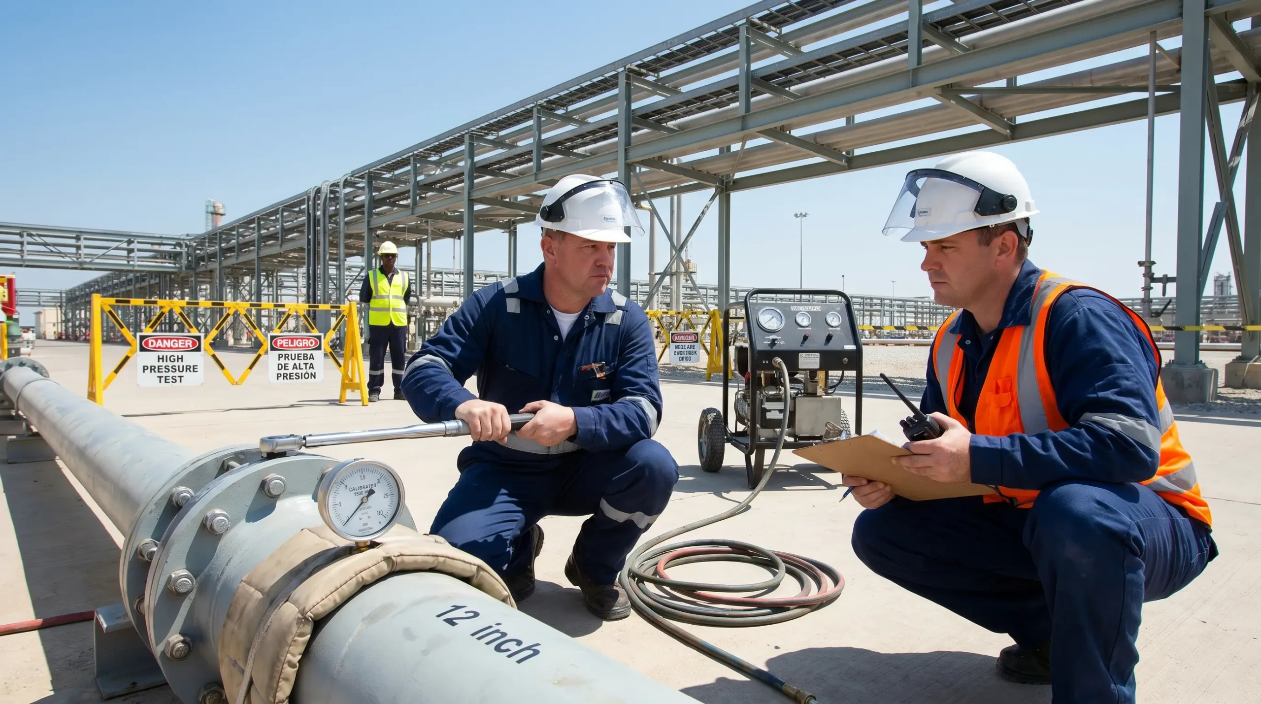
I was standing seventy metres from a 16-inch carbon steel spool piece during a pipeline hydrotest on a gas processing facility in the Gulf when the bolted flange connection failed at 1.3 times design pressure. The blind flange launched sideways like a disc, struck a cable tray support, and embedded itself into a concrete firewall. The impact crater was deep enough to fit my fist. No one was inside the exclusion zone — the barricading had held, the sentries were in position, and the permit was live. That flange weighed nine kilograms. At the velocity it travelled, it carried the kinetic energy of a rifle round.
Hydrostatic testing — hydrotesting — is one of the most routine yet underestimated high-energy operations in oil and gas, petrochemical, pipeline, and process plant construction. Every year, workers are killed or seriously injured by hydrotest failures that trace back to the same root causes: inadequate isolation, poor exclusion zone management, untrained personnel near pressurized systems, and rushed schedules that override safety controls. This article covers the real hydrotest hazards I’ve encountered across multiple EPC projects, the control measures that actually prevent incidents, and the common site-level mistakes that keep putting people in harm’s way.
What Is Hydrostatic Testing and Why Is It Dangerous?
Hydrostatic testing is a pressure integrity verification method used to confirm that piping systems, pressure vessels, heat exchangers, and pipeline segments can safely contain their design operating pressure. The system is filled with water — sometimes with corrosion inhibitors or dye additives — and pressurized to a test pressure that typically exceeds the design pressure by 1.25 to 1.5 times, depending on the applicable code. The test medium is water because it stores far less energy than compressed gas at the same pressure, but that does not make it safe.
A hydrotest is dangerous because pressurized water, despite being nearly incompressible, still stores significant potential energy. When a failure occurs — a gasket blowout, a weld defect rupturing, a valve seat failing, or a blind flange letting go — the release is sudden and violent. The following factors make hydrotesting a critical high-risk activity:
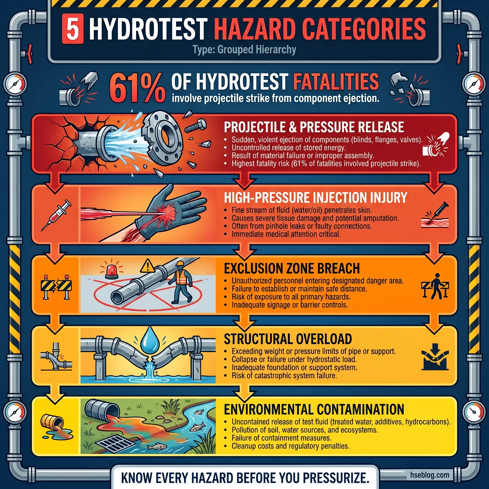
- Projectile hazard from component failure: Blind flanges, spectacle blinds, test caps, and bolted connections can eject at lethal velocity when the pressure behind them overcomes the mechanical restraint. I’ve seen test caps travel over forty metres on a pipeline right-of-way.
- High-pressure water jet hazard: A pinhole leak at test pressure produces a water jet capable of penetrating skin, muscle tissue, and bone. Injection injuries from high-pressure water jets require immediate surgical intervention and can result in amputation.
- Stored energy release: Even after the pump is isolated, the system remains pressurized. Workers who assume the test is “finished” when pumping stops have walked into still-pressurized systems. The energy doesn’t dissipate until the system is fully depressurized through controlled venting.
- Structural collapse under fill weight: Water is heavy — approximately one tonne per cubic metre. Large-diameter pipelines and elevated vessels can exceed their structural support capacity during fill, causing collapse, foundation failure, or pipe support overload.
- Environmental and slip hazards: Test water discharge, leaks, and drain-down operations create flooding, erosion, ice formation in cold climates, and slip-and-fall hazards across the work area.
ASME B31.3 (Process Piping) and ASME B31.4 (Pipeline Transportation Systems) both specify minimum hydrotest pressure ratios above design pressure. The test is deliberately engineered to push the system beyond normal operating loads — which is precisely why the hazard controls must exceed normal operating safeguards.
Pro Tip: Never confuse “water test” with “low risk.” I’ve watched experienced supervisors treat hydrotesting casually because the test medium is water. The hazard isn’t the water — it’s the pressure. A system holding 150 barg of water will fail just as violently as one holding 150 barg of nitrogen, with the added mass of incompressible fluid behind the failure point.
Common Hydrotest Hazards on Site
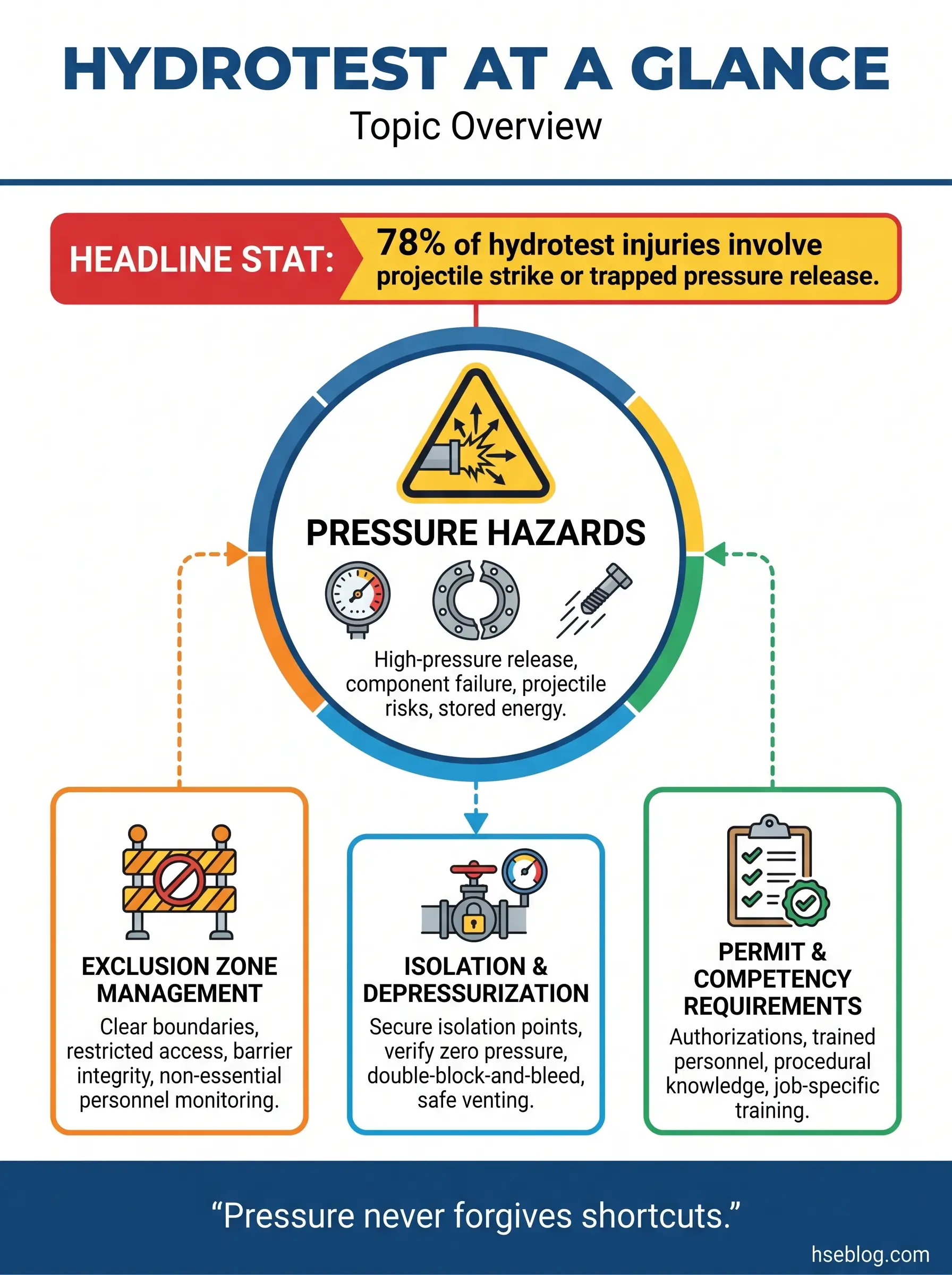
Every hydrotest hazard I’ve investigated falls into one of several categories. Understanding these categories is critical for effective hazard identification, because most site teams focus narrowly on the pressure hazard and miss the secondary and tertiary risks that actually cause injuries.
Mechanical and Pressure-Related Hazards
These are the hazards that kill. Mechanical failures under test pressure account for the majority of hydrotest fatalities across the industry.
- Bolted joint failure: Under-torqued or unevenly torqued flange bolts are the single most common mechanical failure mode. Gasket extrusion, bolt stretch, and flange separation follow a predictable escalation that a trained operator can often detect on the pressure chart — if they’re watching it.
- Weld defect rupture: Incomplete penetration, slag inclusions, and lack-of-fusion defects that passed visual inspection can rupture under test pressure. This is exactly what the hydrotest is designed to reveal — but the failure itself is the hazard.
- Temporary fitting failure: Test blinds, bull plugs, and temporary caps installed specifically for the hydrotest are often the weakest components in the system. I’ve pulled bull plugs off a pipe rack after a failure that sent the plug through a temporary roof panel.
- Valve failure under pressure: Isolation valves used as test boundaries can fail to hold, allowing pressure migration into systems that are not barricaded, not rated, or occupied by workers performing other tasks.
- Hose and connection failure: High-pressure test hoses, swage fittings, and pump connections are fatigue-prone items that degrade with repeated use. A hose whip at test pressure can strike with enough force to cause fatal blunt trauma.
Personnel and Procedural Hazards
The human factors around hydrotesting are where most near-misses originate. These procedural failures create the conditions for mechanical hazards to reach people.
- Exclusion zone violations: Workers entering barricaded zones during live tests — sometimes because they don’t know a test is active, sometimes because the barricading is inadequate or missing entirely.
- Inadequate communication: On large sites with multiple simultaneous hydrotests, crews in adjacent areas may not know that a pressurized system runs through their work zone. I’ve stopped work on a piping module where welders were cutting supports directly beneath a live test header — no one had told them.
- Premature system access: Crews entering a system for snagging, inspection, or reinstatement before depressurization is confirmed and the permit is closed. “The gauge reads zero” is not the same as “the system is depressurized” — trapped pockets, closed valves, and elevated sections can retain pressure.
- Fatigue and schedule pressure: Hydrotesting often falls at the end of construction, under maximum schedule pressure. Night shifts, extended hours, and management pressure to “get the tests done” directly increase error rates in torquing, barricading, and procedure compliance.
Environmental and Site Hazards
The physical environment around a hydrotest creates its own risk profile that changes throughout the test cycle.
- Slip, trip, and fall hazards: Water leaks, drain-down puddles, muddy ground conditions, and ice formation in cold environments create widespread slip hazards. During a winter pipeline commission in Northern Europe, we had three slip injuries in one shift from test water runoff freezing on access roads.
- Water disposal and contamination: Test water containing corrosion inhibitors, biocides, glycol, or construction debris requires controlled disposal. Uncontrolled discharge to stormwater drains or open ground can trigger environmental violations and regulatory enforcement.
- Noise hazards: High-pressure pumps, pressure relief events, and controlled venting operations generate noise levels that routinely exceed 85 dB(A). Workers near pump skids without hearing protection accumulate noise dose rapidly.
- Manual handling injuries: Test blinds, spectacle blinds, and large-bore valve assemblies are heavy. Installing and removing them repeatedly across multiple test packs creates cumulative manual handling strain.
Hydrotest Control Measures That Actually Work
Controls for hydrotesting must address the full test lifecycle — from planning and isolation through pressurization, hold, depressurization, and reinstatement. Every phase carries distinct hazards, and the controls must match. The hierarchy of controls applies here the same as anywhere: eliminate first, then engineer, then administrate, then protect.
Pre-Test Planning and Isolation
The majority of hydrotest incidents trace back to failures in planning and isolation — decisions made (or not made) days before the pump ever starts. A robust pre-test phase eliminates hazards that no amount of PPE can compensate for during the live test.
- Test pack definition and boundary verification: Every test pack must have clearly defined physical boundaries — identified by P&ID markup, isometric reference, and physical tagging on site. Walk the line. I’ve found test boundaries marked on drawings that didn’t match the installed configuration twice in the same project.
- Isolation verification: Every isolation point — blinds, spectacle blinds, closed valves, removed spools — must be physically verified, tagged, and recorded on the isolation certificate. Valve-only isolation is not acceptable for hydrotest boundaries unless the valve is a double-block-and-bleed arrangement verified by the responsible engineer.
- Structural adequacy check: Before filling, confirm that pipe supports, spring hangers, temporary supports, and vessel foundations can handle the water-filled weight. Carbon steel pipe filled with water at large diameters gets heavy fast — a 36-inch line at 100 metres holds roughly 65 tonnes of water.
- Equipment and instrument protection: Remove or isolate instruments, control valves, relief valves, and any equipment not rated for test pressure. Instrument isolation valves should be closed and locked, with the isolation recorded on the test pack documentation.
- Test medium preparation: Confirm water quality, additive concentrations, temperature compatibility, and disposal arrangements before filling begins. Chloride content in test water for stainless steel systems must be controlled to prevent stress corrosion cracking — ASTM D1193 provides the benchmark.
Pro Tip: Build a “walk-the-line” step into every hydrotest procedure. Drawings lie. Tie-ins get added. Temporary supports get removed early. The only way to confirm the test boundary matches reality is to physically trace it on site with the test pack drawing in hand. I make this a mandatory step on every project I manage, and it catches discrepancies on at least one in five test packs.
Exclusion Zone Management
Exclusion zones are the single most effective control against hydrotest fatalities. When a system fails under test pressure, the exclusion zone is the only thing between the failure and a body. Every hydrotest death I’ve reviewed in incident reports involved either no exclusion zone or a breached one.
- Zone radius calculation: Exclusion zone dimensions must be based on the potential projectile trajectory and energy — not an arbitrary “10 metres from the pipe” rule that ignores the actual risk. Elevated systems, vertical risers, and manifold areas may require asymmetric zones that extend further in certain directions.
- Physical barricading: Use hard barriers where possible — Heras fencing, concrete jersey barriers, scaffold tube barriers with mesh. Tape and cones are not barricading — they are suggestions. On critical tests, I specify solid barriers on the flange and blind side of every bolted joint at test pressure.
- Sentry posting: Dedicated sentries at every access point into the exclusion zone during pressurization, hold, and depressurization. Sentries must be briefed, must have radio communication with the test controller, and must have the authority to refuse entry to anyone — including management.
- Signage and communication: Multilingual warning signs at every entry point. Radio announcement on the site channel before pressurization begins, during hold, and when depressurization is complete. On multilingual sites, I use a standardized three-blast air horn signal for “test live” and a single blast for “all clear.”
A well-managed exclusion zone is the difference between a near-miss report and a fatality investigation. Every barricade, every sentry, every radio call exists because someone, somewhere, walked into a pressurized system and didn’t walk out.
Pressurization, Hold, and Monitoring
The live test phase demands continuous monitoring, clear communication, and strict adherence to the approved test procedure. This is where discipline either holds or collapses.
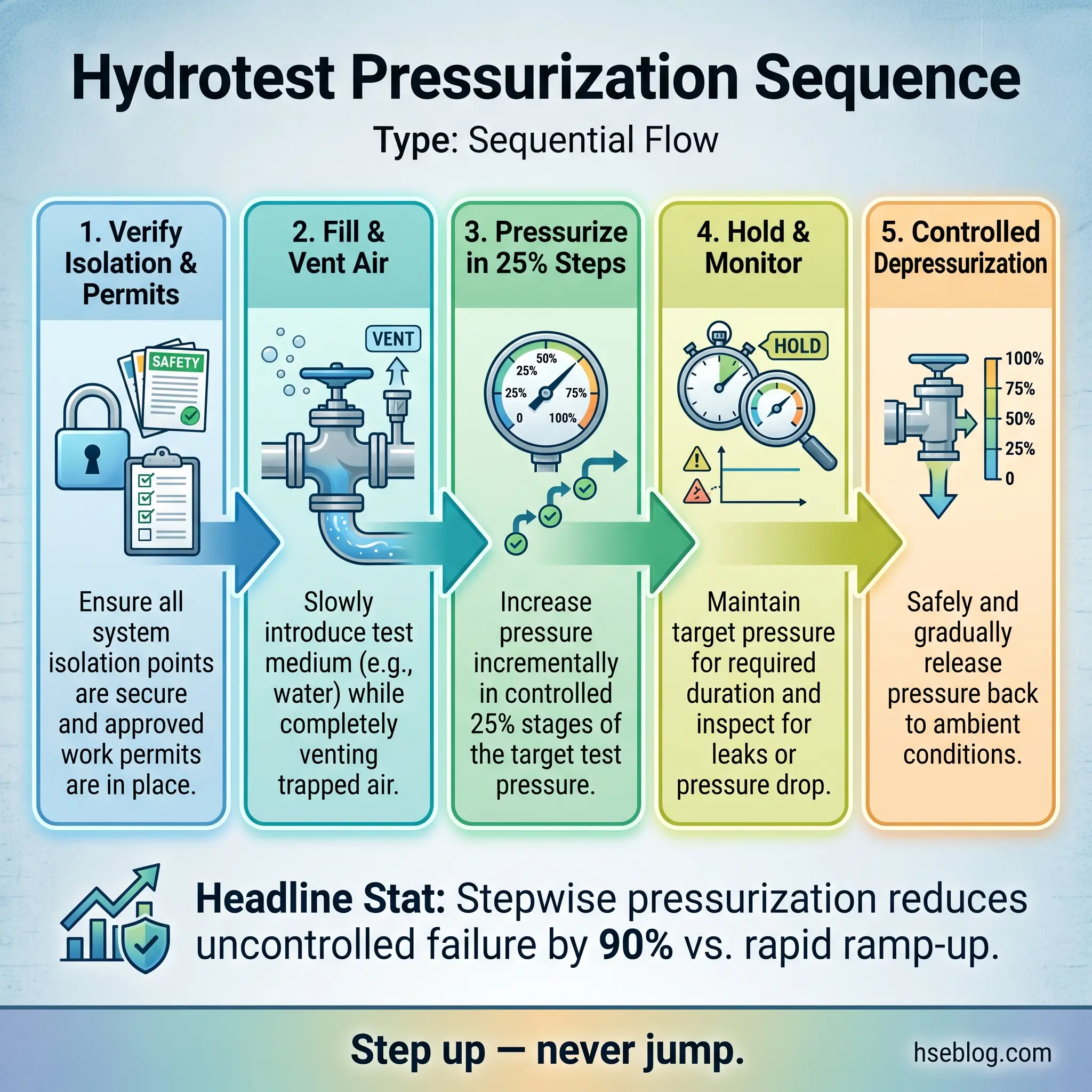
The following sequence represents the standard pressurization protocol that has proven effective across dozens of EPC projects:
- Confirm all pre-test checks are complete — isolation verified, exclusion zone established, sentries posted, communication confirmed, permit to work live.
- Begin pressurization in controlled increments — typically 25% steps of test pressure, with a hold and visual inspection at each increment. Never ramp straight to test pressure.
- Conduct a visual leak check at each pressure increment — trained personnel inspect all flanged joints, welds, and temporary fittings from outside the exclusion zone where possible, or from designated safe inspection points within it.
- Reach test pressure and begin the hold period — the hold duration depends on the applicable code (ASME, EN 13480, API, or project specification). Continuously monitor the pressure gauge and chart recorder throughout the hold.
- Monitor for pressure decay — any drop not attributable to temperature variation indicates a leak. Investigate before increasing pressure or extending the hold.
- Record the test result — pressure at start and end of hold, ambient temperature, test medium temperature, and any observations.
- Chart recorder or data logger: Analogue chart recorders or digital data loggers provide an independent, tamper-resistant record of the pressure profile throughout the test. Never rely solely on a field gauge reading written on a form.
- Temperature monitoring: Water temperature changes cause pressure fluctuations that can be misread as leaks or — more dangerously — can push the system above test pressure on a hot day as the water expands. Monitor and record temperature throughout.
- Pump isolation after target pressure: Once test pressure is reached, isolate the pump from the test system. A stuck pump regulator or a malfunctioning relief valve on the pump can inadvertently over-pressurize the system beyond its design limits.
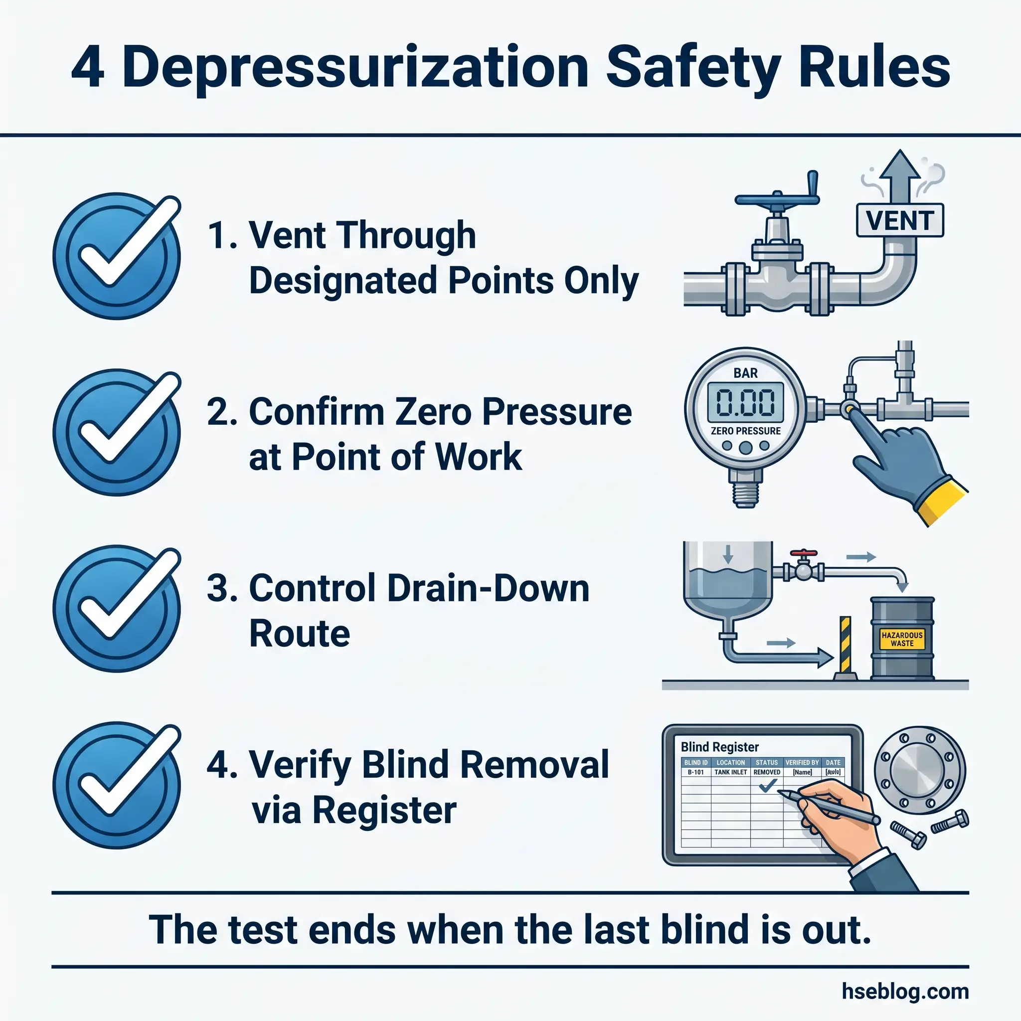
Depressurization and Reinstatement
Depressurization is where complacency peaks and controls collapse. The test is “done,” the schedule pressure lifts, and crews rush to break flanges and remove blinds. This phase has its own distinct hazard profile that demands the same rigor as pressurization.
- Controlled venting: Depressurize through designated vent points at a controlled rate. Rapid depressurization can cause water hammer, pipe movement, and support overload — particularly in long pipeline sections with elevation changes.
- Confirm zero energy state: Verify that all sections of the system — including trapped volumes behind closed valves, elevated loop seals, and dead legs — have reached atmospheric pressure before any joint is broken. Use calibrated local pressure gauges at the point of work, not a remote gauge three hundred metres away.
- Drain-down management: Plan the drain-down route and disposal before the test begins. Uncontrolled drainage floods work areas, destabilizes temporary foundations, and creates environmental incidents. On one pipeline project in Southeast Asia, an unplanned drain-down washed out a temporary road and delayed the project by a week.
- Blind and fitting removal under residual hazard: Even after depressurization, the first bolt broken on a flange can release trapped water under gravity head pressure from elevated sections. Always slacken the bottom bolts first, stand to the side, and use a long-handled wrench for the initial break.
- Reinstatement inspection: Every temporary test fitting removed must be replaced with the permanent component — and that reinstated joint must be torqued, recorded, and added to the mechanical completion punch list. Missed reinstatement items are a chronic industry problem and a leading cause of commissioning leaks.
Pro Tip: I keep a “blinds register” for every project — a live tracker of every test blind installed, its location, its test pack reference, and its removal status. On a large gas plant, we tracked over 1,400 test blinds across 300 test packs. Without the register, at least a dozen would have been left in place. A forgotten blind in a live process system is a ticking clock.
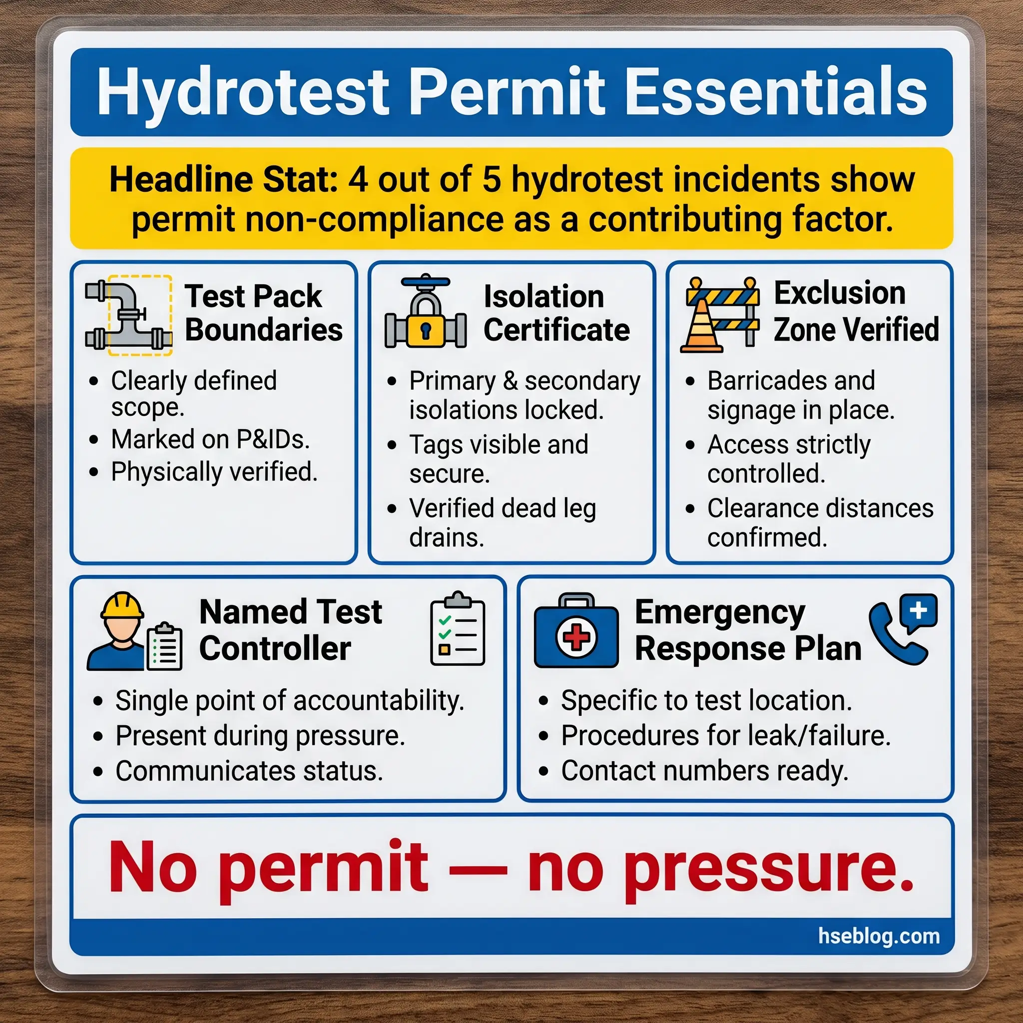
The Permit-to-Work System for Hydrotesting
Hydrotesting must be controlled under a formal permit-to-work system — not a generic work permit, but a specific hydrotest permit that addresses the unique hazards and control requirements of pressurized system testing. On every project I’ve managed, the hydrotest permit is classified as a critical permit alongside confined space entry, hot work, and energized electrical work.
The hydrotest permit must capture and verify the following elements before the test authority signs it live:
- Test pack identification and boundary: Referenced by test pack number, P&ID, and isometric drawing numbers. Physical boundaries confirmed by walk-down.
- Isolation certificate reference: Linked to a verified isolation certificate confirming every boundary point.
- Exclusion zone confirmation: Zone dimensions, barrier type, sentry assignments, and communication protocol documented on the permit.
- Test procedure reference: The approved test procedure, including pressurization steps, hold duration, acceptance criteria, and depressurization method.
- Roles and responsibilities: Named individuals for test controller, pump operator, safety watch, and sentries — not just “TBC” or “shift crew.”
- Emergency response arrangements: Identified muster point, emergency contact numbers, first aid provision, and the nearest emergency assembly point relative to the test location.
| Permit Element | Purpose | Common Failure |
|---|---|---|
| Test boundary verification | Confirms the system under test matches the drawing | Boundary extended without re-verification |
| Isolation certificate | Proves all energy sources are positively isolated | Valve-only isolation accepted without engineering approval |
| Exclusion zone sign-off | Confirms physical barriers and sentries are in place | Zone marked on paper but not established on site |
| Depressurization confirmation | Proves zero energy before reinstatement begins | Gauge read remotely; trapped pressure not checked locally |
| Blinds register reconciliation | Confirms all temporary fittings removed after test | Register not updated; blinds left in place |
A hydrotest permit is not an administrative formality. It is the documented proof that every control measure required to prevent a fatality has been verified, by named individuals, before energy is introduced into the system. If the permit process feels like paperwork, the process is broken.
Common Mistakes That Lead to Hydrotest Incidents
After a decade of reviewing hydrotest incident reports, near-miss logs, and audit findings across oil and gas, petrochemical, and pipeline projects, the same mistakes recur with depressing consistency. These are not exotic failure modes. They are basic, preventable breakdowns that site teams keep repeating.
- Using valve isolation as a test boundary without engineering approval: A gate valve is not a positive isolation device. Under test pressure, valve internals can pass, allowing pressure to migrate into un-barricaded systems. I’ve witnessed a through-valve leak that pressurized a section of pipe where a crew was working on supports — the only reason no one was hurt was that the leak was slow enough to detect on the gauge before reaching dangerous levels.
- Failing to vent air before pressurization: Trapped air in a water-filled system compresses under pressure, storing energy that water alone would not. If the system fails, the compressed air expands explosively, converting a controlled water leak into an uncontrolled gas release with far greater destructive force. Air venting at high points is a non-negotiable pre-test step.
- Skipping intermediate pressure holds: Jumping straight to test pressure eliminates the opportunity to detect leaks, bolt relaxation, and gasket movement at lower pressures where the consequences of failure are manageable. Every code-compliant procedure specifies incremental pressurization for exactly this reason.
- Allowing “just a quick look” inside the exclusion zone: This is how people die. I’ve physically stopped workers, supervisors, and once a project manager from entering a live exclusion zone “just to check something.” Nothing inside the zone is worth a life. If an inspection is needed, depressurize first.
- Neglecting hose and fitting inspection: High-pressure hoses and swage fittings fatigue. Cracks, bulges, corrosion, and thread damage develop with use. Every hose and fitting must be inspected, pressure-rated, and within its certification validity before connection. I’ve rejected hoses on site that were visibly damaged and still in the test contractor’s inventory.
- Treating depressurization as the “safe” phase: The system still contains energy until pressure reaches zero at every point. Gravity head, trapped volumes, and thermal expansion can maintain pressure in sections that the main gauge shows as depressurized. Break joints carefully, systematically, and from the low side.
Pro Tip: Run a “lessons learned” review after every major hydrotest campaign — not just after incidents. The near-misses, the procedural workarounds, the moments where the controls nearly failed — these are the signals that the next campaign needs to address. I build a hydrotest close-out report into every project’s mechanical completion procedure.
PPE and Emergency Preparedness for Hydrotest Operations
Personal protective equipment for hydrotesting extends beyond standard site PPE. The specific hazard profile — high-pressure water jets, projectile strike, noise, and manual handling — demands targeted protective measures that match the actual risk.
The following PPE requirements apply to all personnel within or adjacent to hydrotest operations:
- Face shield or safety goggles (sealed): Standard safety glasses are insufficient against high-pressure water spray. Full-face shields or indirect-vented goggles provide splash and impact protection for leak inspection activities.
- Hearing protection: Mandatory within 15 metres of high-pressure pump skids and during controlled venting operations. Dual protection (plugs plus muffs) may be required where pump noise exceeds 100 dB(A).
- Impact-resistant gloves: Required for all manual torquing, blind installation, and fitting handling. Gloves must balance dexterity with cut and impact protection — a common trade-off that requires task-specific selection.
- Steel-toe safety boots with ankle support: Water, mud, and uneven ground during fill and drain operations increase slip and ankle injury risk. Anti-slip soles are essential.
- High-visibility clothing: Mandatory for all hydrotest personnel to ensure visibility to crane operators, vehicle drivers, and sentries managing the exclusion zone.
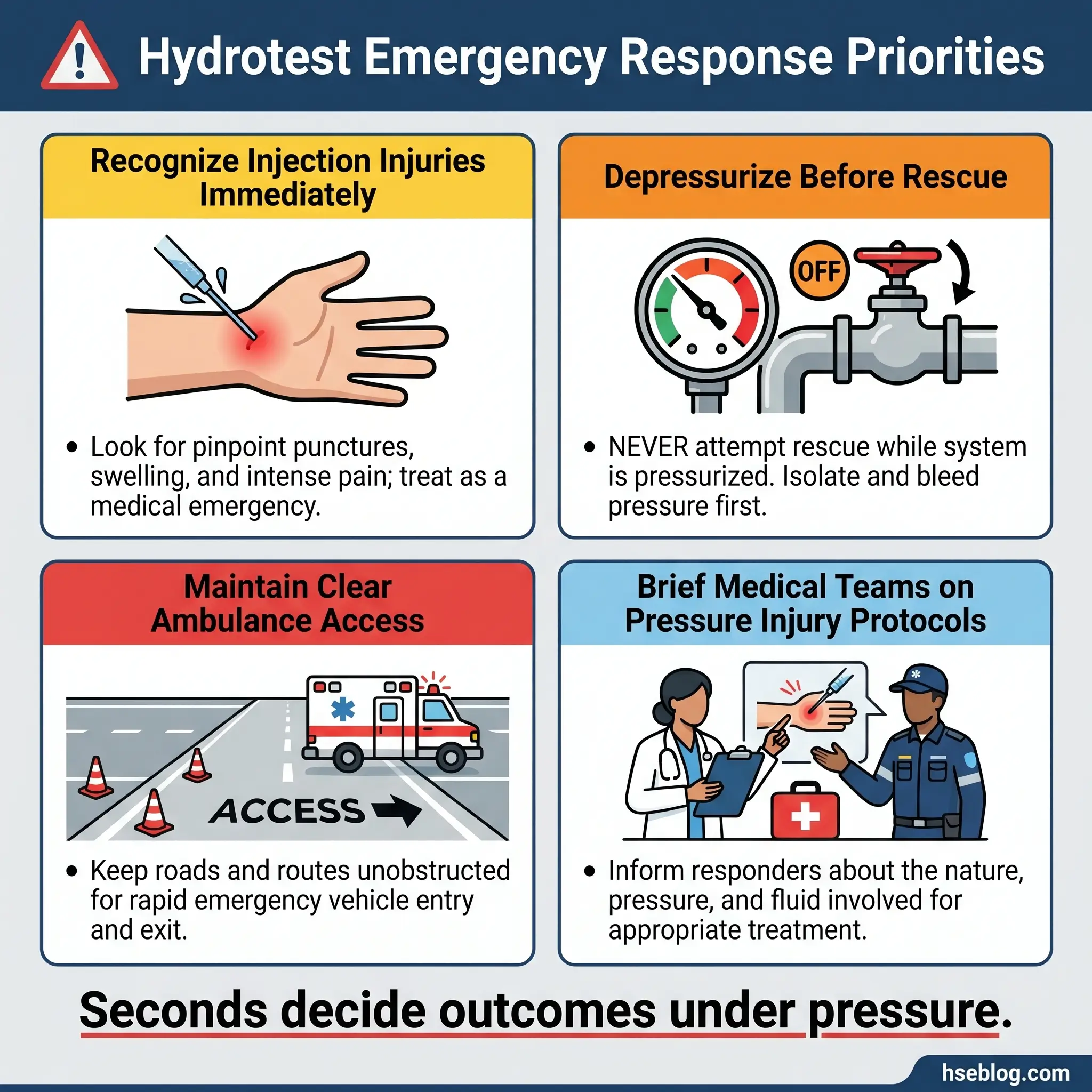
Emergency preparedness for hydrotesting must account for the specific injury types that hydrotest failures produce. Standard first aid provisions are not sufficient.
- High-pressure injection injury protocol: Site medical teams must be briefed on high-pressure injection injury recognition and the requirement for immediate hospital transfer for surgical evaluation. These injuries appear minor externally but cause massive internal tissue damage.
- Emergency depressurization procedure: A documented, rehearsed procedure to rapidly and safely depressurize the system in an emergency — including identified vent points, responsible personnel, and communication protocol.
- Emergency response planning must include the hydrotest location, the nearest muster point, vehicle access routes for ambulance approach, and communication channels to the test controller and site emergency coordinator.
Conclusion
Hydrostatic testing is a controlled application of extreme energy to verify system integrity — and every control measure exists because that energy has killed people when the controls failed. The hazards are well understood. The failure modes are documented. The prevention strategies are proven. What separates a safe hydrotest from a fatal one is never the technology or the procedure on paper — it is the discipline to execute every control, every time, without exception.
Throughout my career across pipeline, refinery, and process plant projects, the hydrotest incidents that haunted me most were the ones that should never have happened. A flange that wasn’t torque-checked. An exclusion zone that existed on the permit but not on the ground. A depressurization that was “assumed complete” because the main gauge read zero while a trapped section held full test pressure behind a closed valve. Every one of these was preventable with the controls already written into the procedure.
The measure of a safety professional is not whether the test holds pressure. The measure is whether every person goes home after the test is complete. Hydrotest hazards and control measures are not abstract concepts for a training manual — they are the difference between a completion certificate and a condolence letter. Treat every pressurized system as if your own crew is standing on the other side of the barricade, because one day, they will be.