
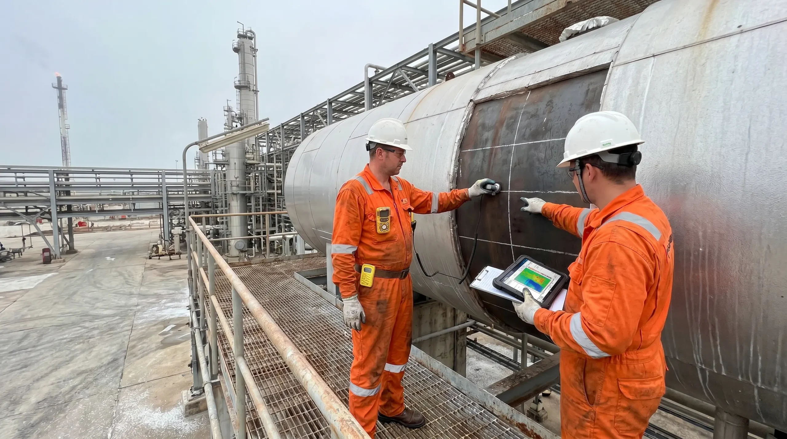
Put your palm on the steel shell of a 30-metre propane sphere at an olefins plant on a coastal industrial strip, and the metal feels ordinary — cool, slightly gritty under paint. Behind that 40 mm of plate sits roughly 2,000 cubic metres of liquefied hydrocarbon at 17 barg, held there by nothing more than metallurgy, welds, two pressure relief valves, and a design that assumed nobody would forget what’s inside. Every pressure vessel — from that sphere down to the 300-litre compressed-air receiver in a packaging hall — is the same bargain. A ductile steel wall stands between stored energy and the people working nearby, and the wall only stays a wall as long as discipline holds.
Pressure vessel safety is the discipline of keeping that bargain honest. It covers how vessels are designed, built, operated, inspected, and retired, and when any one of those links breaks, the consequences are not proportional to the mistake. A missed thickness reading, a pressure relief valve left isolated, a cold startup below the material’s ductile transition — any of them can put shrapnel 400 metres downrange and a blast wave through a control room. This article walks through what a pressure vessel actually is under the codes, why the stored energy inside makes it categorically different from an atmospheric tank, the specific pressure vessel hazards it creates, why vessels fail, how the hierarchy of controls applies to pressure equipment, and the international regulatory framework — ASME BPVC 2025, PED 2014/68/EU, and UK PSSR 2000 — that governs the discipline today.
What Is a Pressure Vessel? A Safety-First Definition
Engineering definitions of a pressure vessel differ across codes, but the safety-relevant line is consistent: any closed container engineered to hold a gas or liquid at a pressure substantially above or below ambient enters regulated territory. Under ASME BPVC Section VIII Division 1, that threshold is 15 psig (approximately 1 barg). Under the EU Pressure Equipment Directive 2014/68/EU, it is 0.5 bar gauge. Below those numbers, you have a tank. Above them, you have equipment governed by design codes, material standards, non-destructive examination rules, certification marks, and in-service inspection schedules.
A second distinction matters on the plant floor. A pressure vessel is a single piece of equipment — a reactor, a receiver, a separator, a heat exchanger shell. A pressure system is the vessel plus the piping, valves, relief devices, and instrumentation that make it part of the process. The UK Pressure Systems Safety Regulations 2000 regulate the whole system, not just the vessel, because an ASME-stamped shell with a choked relief line is no safer than a substandard vessel.
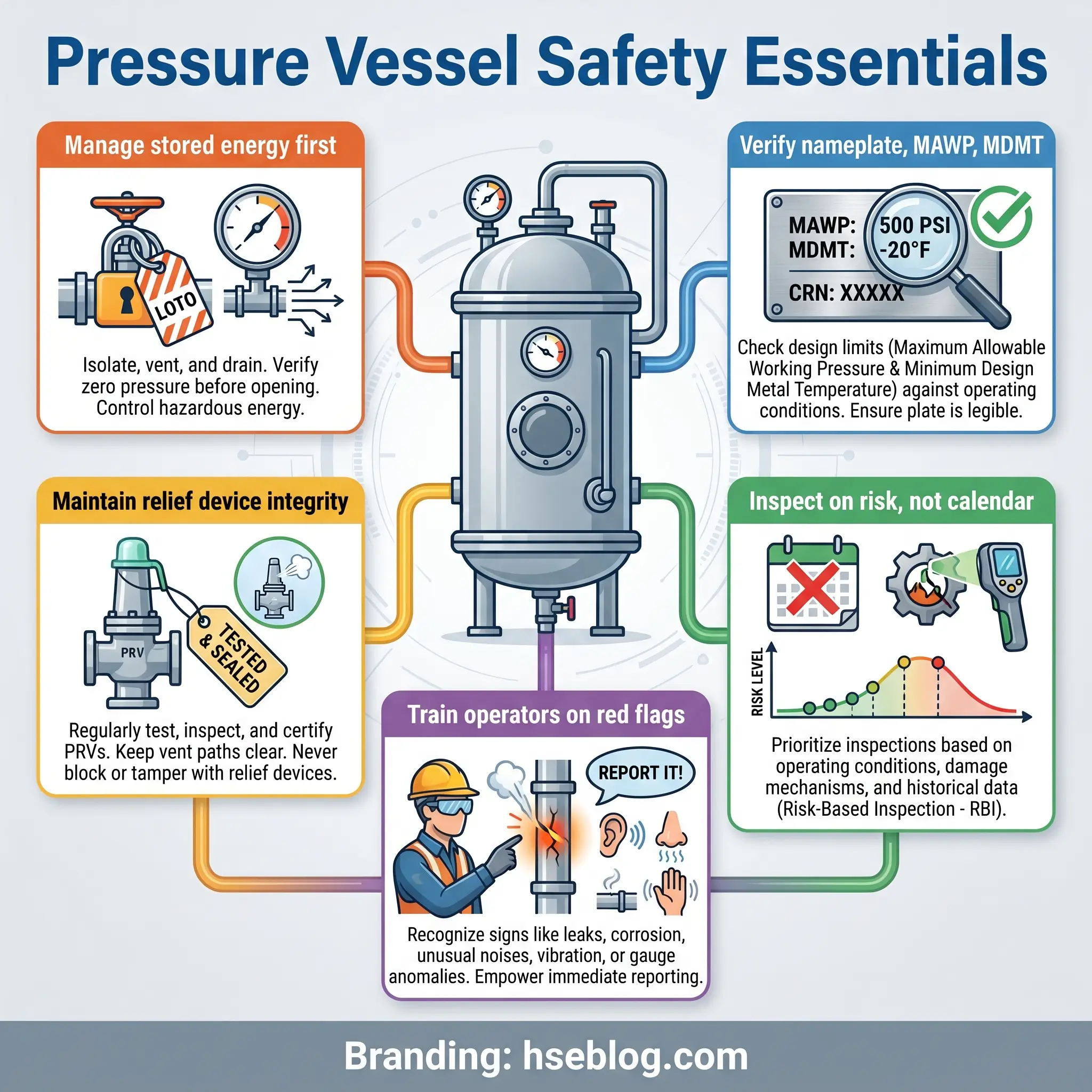
Common examples on any sizable industrial site include boilers, air receivers, autoclaves, LPG storage spheres and bullets, shell-and-tube heat exchangers, distillation columns, reactors, and compressed-gas cylinders. Each carries a nameplate listing its MAWP (Maximum Allowable Working Pressure), design temperature, MDMT (Minimum Design Metal Temperature), manufacturing code stamp, and serial number. That nameplate is the single most important safety document on the vessel. Worn or painted over, it is effectively a lost identity card, and operating a vessel without a readable nameplate is a finding in any serious audit.
Field Test: Walk a unit with a worksheet listing only the tag numbers. For each vessel, try to photograph a clean, legible nameplate in under thirty seconds. On most brownfield sites, roughly one in four will fail. That ratio tells you how good your mechanical integrity data really is.
Why Pressure Vessel Safety Matters: The Stored Energy Problem
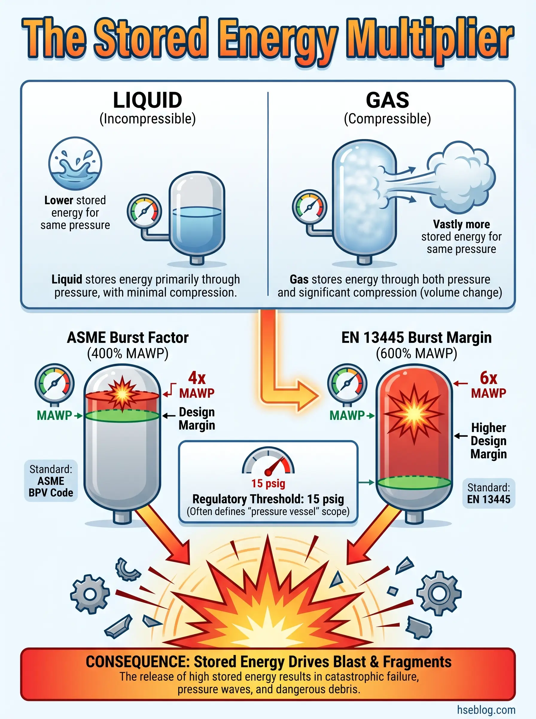
Compressed gas stores far more energy per unit volume than a compressed liquid — the reason a pneumatic rupture is violent and a hydrostatic one is usually a loud hiss and a puddle. Gases are compressible; liquids are not. That single physical fact is why ASME Section VIII defaults to hydrostatic testing at 1.3 × MAWP (UG-99) and permits pneumatic testing at 1.1 × MAWP (UG-100) only when hydrotest is impractical, and even then with controls that treat the vessel as a potential bomb.
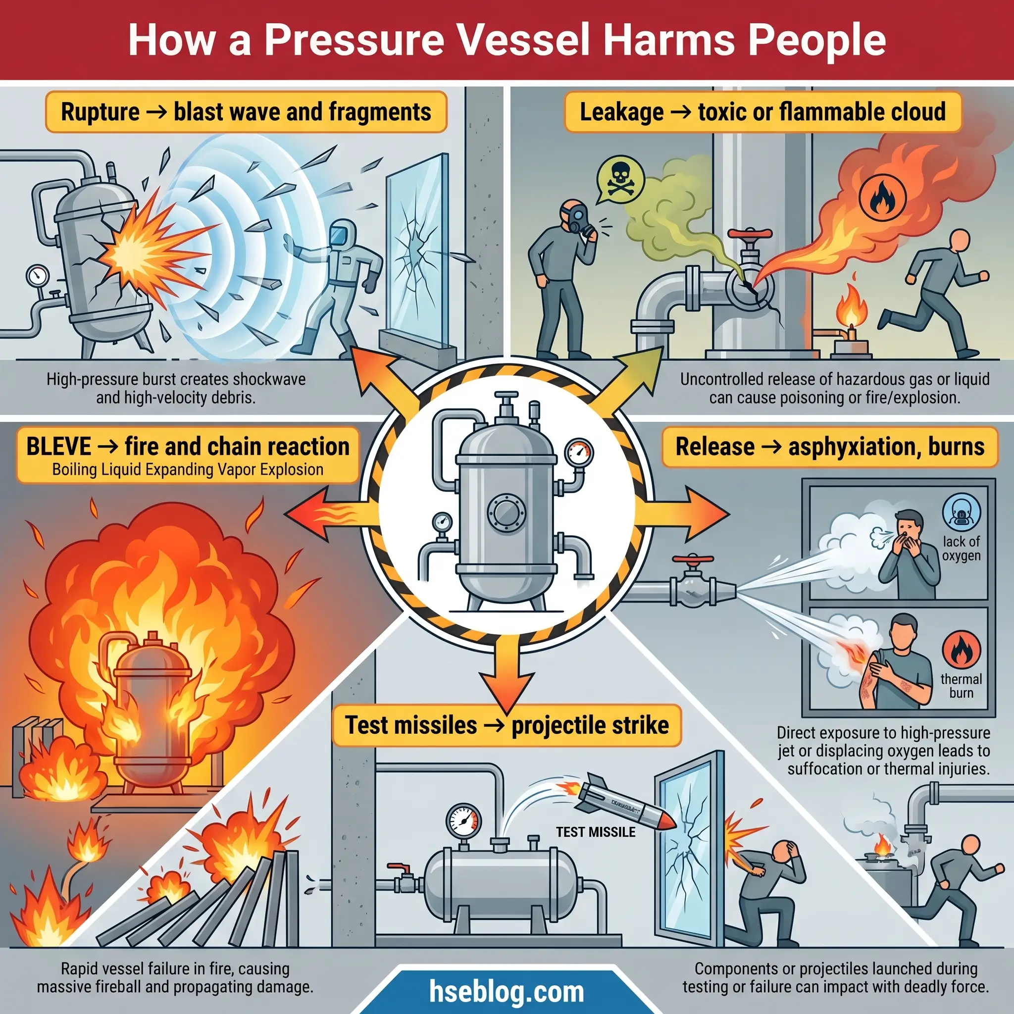
This stored-energy frame explains every downstream consequence. When a pressure vessel loses containment suddenly, that energy converts into three forms: a blast wave that can collapse unreinforced walls and rupture eardrums at tens of metres; fragmentation — plate sections, endcaps, and nozzle stubs travelling as missiles hundreds of metres; and, if the contents are flammable or toxic, a fire, vapour cloud, or toxic exposure downwind. The ASME Boiler and Pressure Vessel Code was not written in the abstract. It exists because the Grover Shoe Factory boiler in Brockton, Massachusetts exploded in 1905, killing 58 workers and injuring 150, and public response forced mechanical engineers to standardise design. Every clause in Section VIII is, in that sense, a named grave.
The 1984 San Juanico LPG terminal disaster remains the high-water mark of what a failed pressure vessel farm can do. Two large spheres and 48 cylindrical vessels were destroyed in a BLEVE chain reaction that killed approximately 600 people and injured over 5,000. The operational lesson was not that spheres fail — it was that stored energy, once initiated, cascades through adjacent vessels faster than anyone can intervene.
Types of Pressure Vessels and Their Characteristic Risks
Not every pressure vessel threatens its surroundings in the same way. Matching controls to vessel type starts with understanding which hazard the service imposes on the shell.
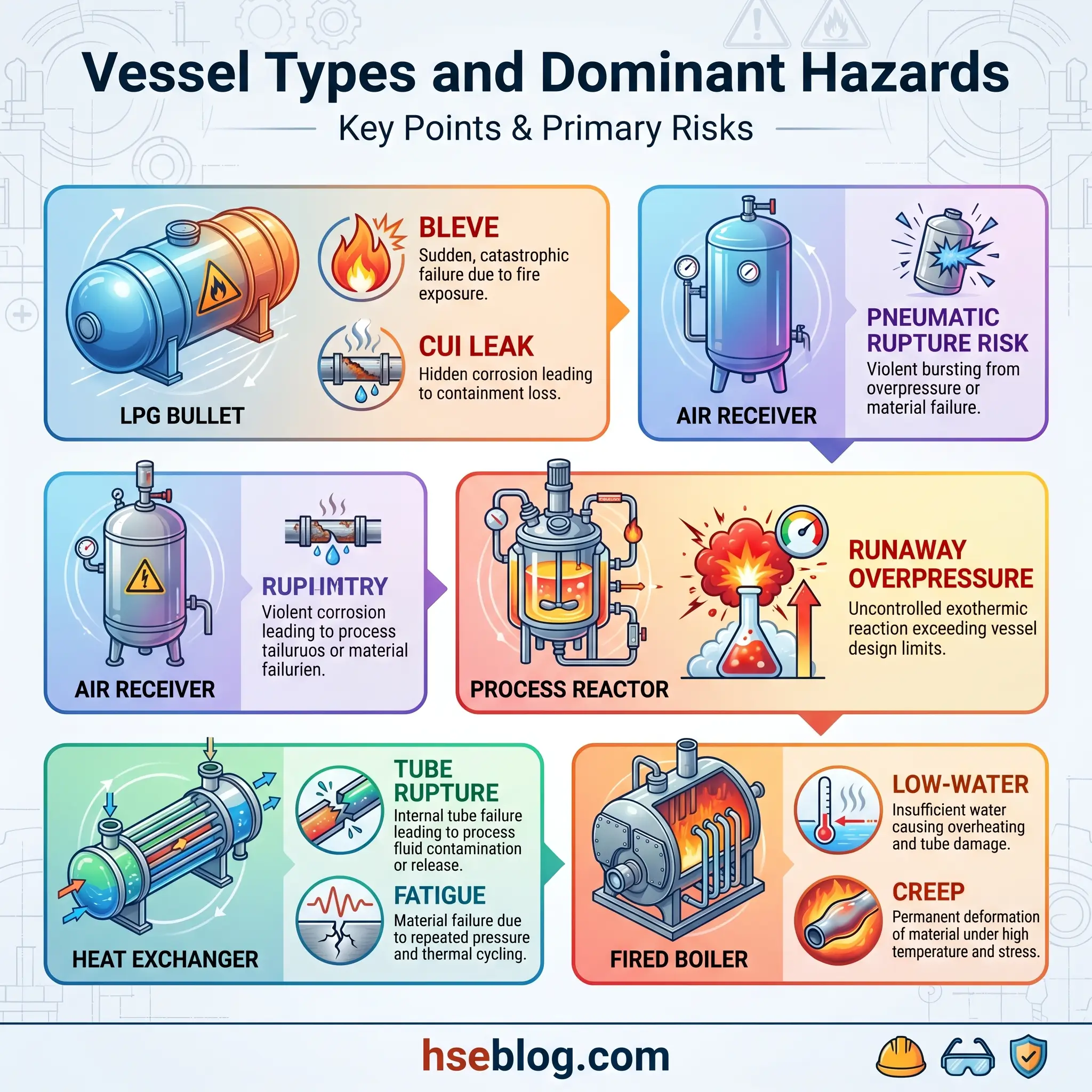
Storage vessels — LPG bullets and spheres, air receivers, cryogenic tanks — live with two slow threats: external corrosion, often hidden as corrosion under insulation (CUI), and the BLEVE scenario when liquefied gas is engulfed in fire. Process vessels — reactors, separators, distillation columns — face overpressure from runaway reactions, loss of cooling, or blocked outlets, plus internal corrosion from the process chemistry. Heat exchangers are dominated by tube-side failures, thermal fatigue from cyclic loading, and cross-contamination between shell and tube sides. Fired vessels add a fuel-side explosion risk, low-water conditions, and long-term creep in tubes operating near their design temperature. Transportable pressure receptacles — gas cylinders — carry impact damage and valve shear as their dominant hazards.
A compact comparison makes the differences concrete:
| Vessel Type | Typical Service | Dominant Hazard | Key Control Focus |
|---|---|---|---|
| LPG bullet / sphere | Liquefied propane, butane | BLEVE, CUI-driven leak | Fire protection, PRV sizing, CUI inspection |
| Air receiver | Compressed air | Pneumatic rupture, corrosion | Condensate drain, PRV test, wall-thickness UT |
| Process reactor | Polymerization, hydrotreating | Runaway reaction overpressure | SIS/SIL shutdown, pressure relief, operator training |
| Shell-and-tube exchanger | Process cooling/heating | Tube rupture, thermal fatigue | Tube-side NDT, inlet erosion monitoring |
| Fired boiler | Steam generation | Low-water, creep, fuel explosion | Water treatment, tube metallography, burner interlocks |
| Gas cylinder | Oxygen, acetylene, inert | Valve shear, impact, contamination | Storage separation, handling training, hydrostatic retest |
The Main Hazards of Pressure Vessels
A risk assessment that lists “pressure hazard” as a single line item misses the five distinct ways a pressure vessel reaches the people around it. Each delivery mechanism carries a different control requirement, which is why generic “safety measures” lists fail where structured hazard mapping succeeds.
Catastrophic Rupture and Blast Effects
Rupture dominates every risk calculation. When the shell of a code-compliant ASME vessel fails, it does so at roughly four times its MAWP — the BPVC’s safety factor of 4. You are not dealing with a vessel slightly over its rating, but with one that has lost a significant fraction of its wall thickness, developed a through-wall crack, or been subjected to an overpressure transient the relief system could not handle. European vessels built to EN 13445 carry roughly 6× burst margins, which changes the statistics but not the physics.
Fragmentation is the underrated consequence. Published accident reconstructions routinely describe shell sections weighing hundreds of kilograms thrown several hundred metres. A plate travelling at 150 m/s does not need to hit a worker to kill. It punches through control-room walls, power transformers, and adjacent piping, initiating secondary events.
Leakage and Loss of Containment
Slow releases are far more common than ruptures, and most ruptures are preceded by leakage. A weep at a flange, a pinhole in a heat exchanger tube, a cracked gauge connection — these are the warnings that distinguish a near-miss database from an incident report.
The hazard profile of a leak depends on what is inside. Hydrocarbons form flammable clouds. H₂S from sour service is lethal at concentrations too low to smell beyond the first few breaths. Cryogenic fluids produce cold burns and oxygen-depleted atmospheres as they vaporise. A leak is also a corrosion-initiation event — process fluid escaping under insulation is one of the common starting points for a CUI programme.
Fire and Explosion (BLEVE, Vapour Cloud)
A Boiling Liquid Expanding Vapour Explosion — BLEVE — is a specific failure mode of liquefied-gas vessels engulfed by an external fire. The fire weakens the shell above the liquid level, where there is no liquid to carry away heat. The weakened plate ruptures, and the entire liquid inventory flashes to vapour in milliseconds. If the contents are flammable, the vapour ignites. The San Juanico chain reaction was initiated when one sphere BLEVE’d and launched fragments into adjacent vessels.
Vapour cloud explosions (VCEs) follow a different pattern. A flammable release disperses, finds an ignition source, and detonates if the cloud is confined by equipment or structures. Open-plant releases usually deflagrate. Congested module releases can detonate, which is an order of magnitude worse in overpressure terms — and one of the main causes of pressure vessel explosion severity in dense process units.
Asphyxiation, Toxic Exposure, and Chemical Burns
Not every pressure hazard is fire. Nitrogen purging before vessel entry has killed more industrial workers than most people realise; it displaces oxygen without any warning properties. Ammonia, chlorine, H₂S, and carbon monoxide all have exposure limits far below their odour thresholds or above them in ways that produce olfactory fatigue. Process fluids released under pressure cause chemical burns, caustic ingestion injuries, and thermal burns from superheated steam or hot oil.
Projectile and Missile Hazards
The closest-range hazard is fragmentation during pressure testing. Blown manway covers, ejected nozzle plugs, sheared bolts, and ruptured blind flanges have all killed test technicians standing inside what they thought was a safe radius. The pneumatic test rule — that only essential personnel remain within the exclusion zone — exists because the energy stored in a test at 1.1 × MAWP of compressed gas will throw a 10 kg bolt like a bullet.
What Causes Pressure Vessel Failure? Common Failure Modes
The body of incident investigations and fitness-for-service literature published under API 579-1 / ASME FFS-1 converges on one point: catastrophic pressure vessel failures are almost never spontaneous. They are the endpoint of a defect — a crack, a thinning section, a heat-treatment flaw — that has been growing for months or years. Understanding the mode of growth is how inspection programmes are built.
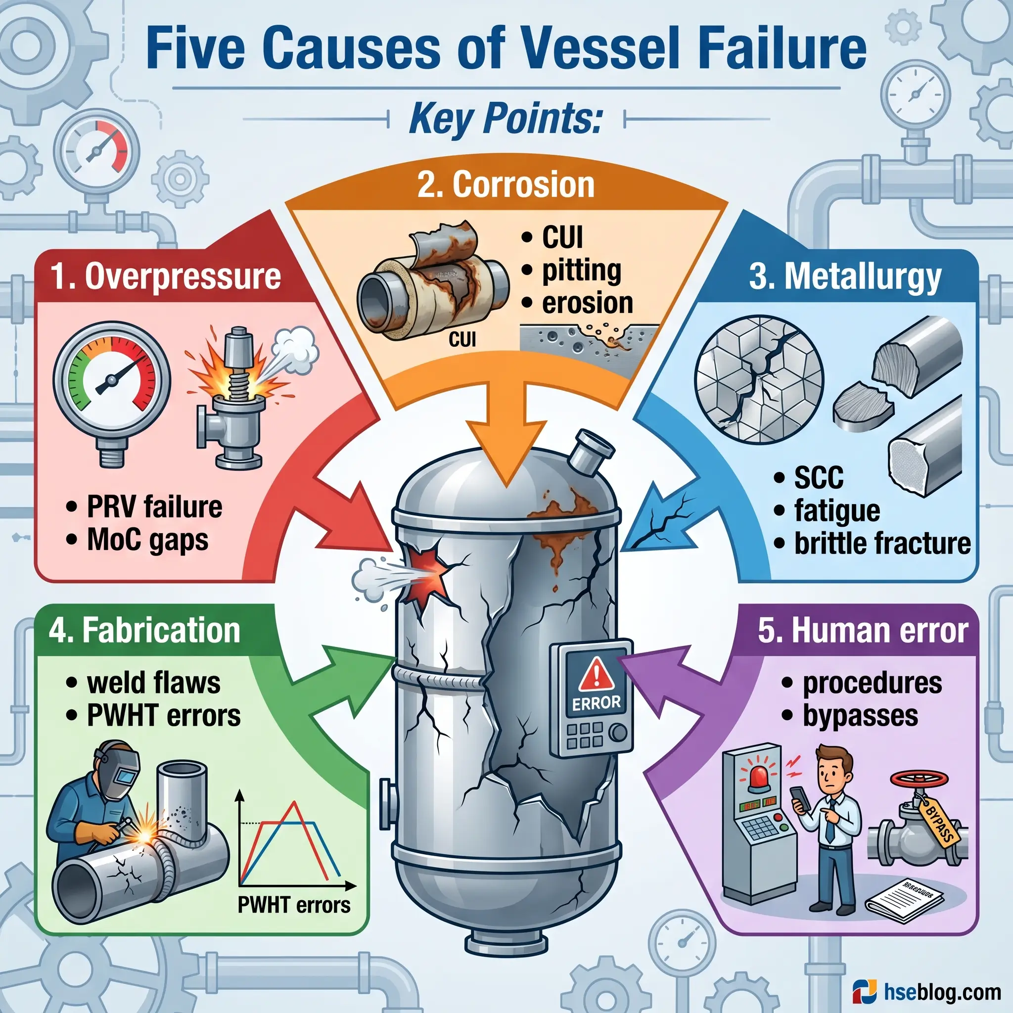
Failure causes fall into three primary groups.
- Overpressure. A vessel sees pressure above its design envelope because a relief valve is undersized, isolated, or fouled; because thermal expansion creates hydraulic lockup in a blocked line; because a chemical reaction runs away; or because a downstream restriction is introduced without a management-of-change review. Overpressure events do not need to reach burst pressure to do damage — repeated excursions above MAWP accelerate fatigue.
- Corrosion and erosion. General wall thinning, localised pitting, corrosion under insulation (CUI), and erosion-corrosion at tees, elbows, and reducers set the inspection interval. A survey of amine service vessels cited in the OSHA pressure vessel safety assessment directive found cracking in roughly 40% of 294 plants studied — not an outlier result, a baseline expectation for that service if not actively managed.
- Metallurgical degradation. Stress corrosion cracking in wet H₂S, amine, caustic, or chloride service; fatigue from cyclic pressure and temperature loading, often at nozzle junctions and weld toes; brittle fracture when a vessel is pressurised below its MDMT — the cold-startup failure mode; and creep in high-temperature service, which sets the retirement date on superheater tubes and reformer outlets.
Two further causes sit outside the metallurgy.
- Fabrication defects — weld lack-of-fusion, porosity, lamination, improper post-weld heat treatment, and dimensional non-conformance that survive a construction QA that was too narrow. Many of these only surface during in-service inspection or a subsequent fitness-for-service assessment.
- Human and procedural error — bypassed interlocks, mis-operation during startup or shutdown, incorrect test medium (compressed air used when hydrotest was specified), and unauthorised modifications. The ResearchGate analysis of CNESST and NIOSH incident data found that 82% of Quebec accidents and 61% of U.S. accidents occurred in small and medium enterprises, with procedural non-compliance — not metal — as the dominant root cause.
Watch For: Insulation staining at the 4 and 8 o’clock positions on horizontal vessels, rust bleed around clip welds, or visible wicking at insulation joints. These are the external signs of CUI that a competent inspector catches before strip-off confirms it.
Pressure Vessel Controls: Applying the Hierarchy of Controls
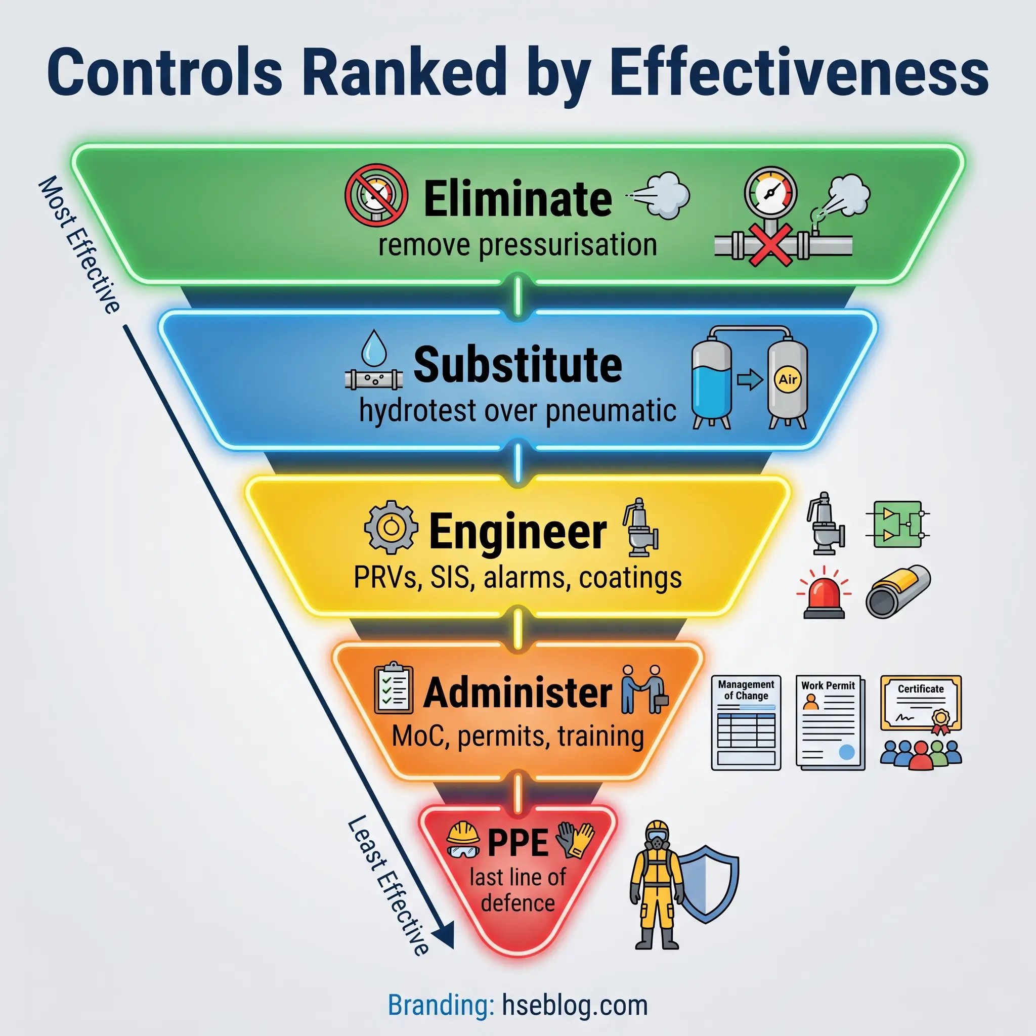
Every HSE professional reading this already uses the hierarchy of controls in risk assessment — elimination at the top, PPE at the bottom. Pressure vessel safety benefits from applying that framework explicitly rather than defaulting to a flat list of pressure vessel controls. The hierarchy tells you which controls to pursue first when budget, engineering, and organisational will are finite.
Elimination and Substitution
The question at the top of the hierarchy is whether the vessel needs to be pressurised at all, and at that pressure. Re-engineering a process to operate at atmospheric, lowering design pressure, or switching from pressurised to gravity-fed transfer removes the hazard rather than controlling it. On the substitution side, hydrotesting with water instead of compressed air, purging with nitrogen before opening rather than ventilating live, and using inherently safer cooling (indirect rather than direct contact) are all substitution-level controls. A colleague who ran a reactor turnaround on a polyolefin train reduced the plant’s pneumatic-test exposure by an order of magnitude simply by re-specifying the helium leak-test procedure to run a hydrotest first — the helium then confirmed remaining leaks at low differential pressure, instead of doing the whole test in compressed helium. The principle holds whenever elimination and substitution can be argued: they remove energy from the system, not just barriers around it.
Engineering Controls (The Primary Line of Defence)
The core of pressure vessel safety sits here.
- Code-compliant design. ASME BPVC Section VIII, EN 13445, or equivalent, with correct material selection for the service fluid, corrosion allowance sized for the design life, and fatigue analysis for cyclic duty. Design-by-rule (ASME Div 1) suits standard service; design-by-analysis (Div 2) is used for higher pressures and fatigue-dominated service.
- Overpressure protection. Pressure relief valves sized per API 520 and set per ASME Section XIII, with rupture discs as secondary protection or as primary devices where the service fouls conventional valves. Every relief device must be sized for the worst credible scenario — fire case, blocked outlet, control valve failure — not the normal operating duty. Pressure relief valve safety requirements also cover set-pressure tolerance, blowdown, and nameplate capacity certification.
- Instrumentation and interlocks. Pressure and temperature transmitters, high-high alarms, and SIS/SIL-rated automated shutdowns that close inlet valves, vent vessels, or trip compressors before a PRV has to lift. The PRV is not the first line of defence. It is the last engineered one.
- Corrosion control. Appropriate internal coatings, cathodic protection where applicable, inhibitor injection in corrosive service, and external coating systems designed for the installation environment. On coastal sites with salt-laden air, external coating specification is not an aesthetic choice — it is a CUI-mitigation control.
- Physical barriers during high-risk tasks. Blast walls, exclusion zones, and barricades during pneumatic testing, reactor commissioning, and first-fill operations.
Administrative Controls
Engineering hardware is only half the control system. Administrative controls are the procedures, competency requirements, and management systems that keep engineered protection functional over the vessel’s life.
- Written operating procedures for startup, normal operation, shutdown, and credible emergency scenarios, each step tied to specific pressure and temperature limits.
- Permit-to-work for vessel entry, hot work on pressurised systems, and all pressure tests, with specific energy-isolation and atmospheric-monitoring requirements.
- Management of Change (MoC) for any modification to MAWP, design temperature, service fluid, protective-device setpoint, or inspection interval. A PRV set-pressure change without MoC is the classic silent failure mode.
- Pressure vessel risk assessment aligned to credible failure scenarios, refreshed after any process change and fed into the inspection plan.
- Isolation and lockout/tagout (LOTO) before any maintenance — the pressure-vessel-specific version includes physical blinding, not just valve closure, for any entry or invasive task.
- Nameplate and labelling integrity — unreadable nameplates taken out of service until re-stamped or re-certified.
Personal Protective Equipment (PPE)
PPE sits last for a reason. It does not prevent a rupture, a leak, or a BLEVE — it reduces the consequence of residual exposure. For pressure vessel work, the standard specification includes ANSI Z87+ safety glasses with side shields, a full-face shield for any task with splash or spray potential, flame-retardant clothing in hydrocarbon service, chemical-resistant gloves and suits matched to the process fluid, and respiratory protection — air-purifying or supplied-air — where toxic release during the task is credible. During a pressure test, the PPE specification extends to hearing protection and limited-access barricades for anyone inside the test boundary.
Pressure Vessel Inspection and Testing: The Cornerstone of Integrity Management
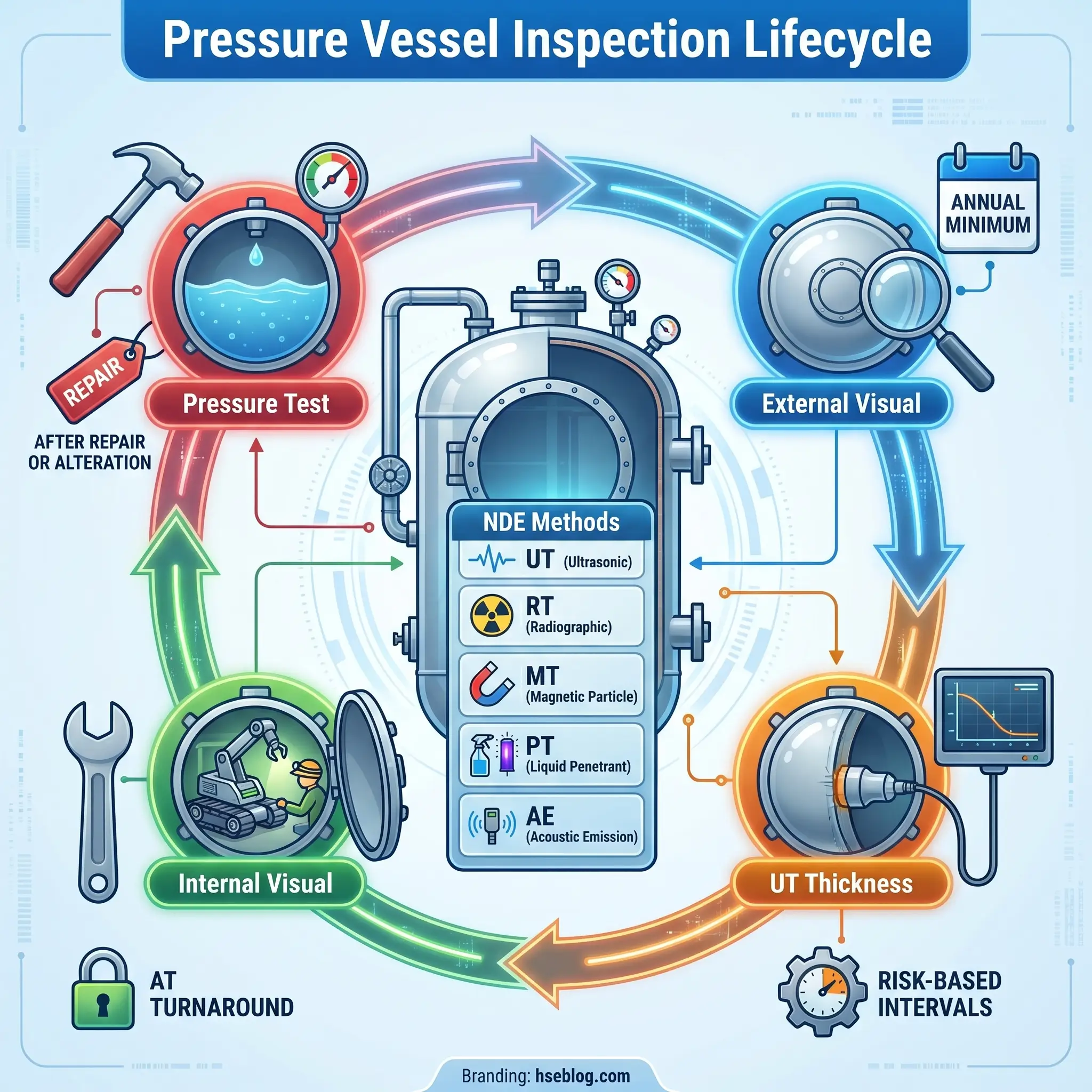
Published root-cause analyses of major vessel failures converge on an uncomfortable truth — almost every catastrophic event was preceded by months or years of detectable degradation that pressure vessel inspection either missed or was not scheduled to find. That is why inspection is the single most effective ongoing control for in-service vessels. Modern mechanical integrity programmes combine external and internal visual examination, non-destructive testing, and periodic pressure testing, increasingly allocated through Risk-Based Inspection (RBI) rather than fixed intervals.
External visual inspection looks for coating damage, insulation degradation, support condition, nozzle alignment, and early CUI indicators. Internal inspection, performed during planned turnarounds, assesses wall condition, weld integrity, internal fouling, and corrosion patterns that cannot be seen from outside.
Non-destructive examination extends the inspector’s senses. Ultrasonic thickness surveys (UT) establish remaining wall and corrosion rates. Radiography (RT) and phased-array UT find weld discontinuities and sub-surface flaws. Magnetic particle (MT) and liquid penetrant (PT) testing locate surface-breaking cracks, particularly at weld toes and nozzle reinforcements. Acoustic emission (AE) listens for active defect growth under test pressure, useful for vessels where thorough NDE is impractical.
Periodic pressure testing verifies integrity after repairs or alterations. ASME Section VIII Division 1 specifies hydrostatic test at 1.3 × MAWP corrected for design temperature (UG-99); pneumatic test at 1.1 × MAWP (UG-100) where hydrotest is impractical and the user accepts the higher stored-energy risk. For pressure relief valves, NBIC Section 2.5.8 recommends manual checks every six months and annual pressure testing for steam boilers between 15 and 400 psi, with three-year intervals for boilers above 400 psi.
| Inspection Type | Typical Frequency | Regulatory Reference |
|---|---|---|
| External visual | Annual (minimum) | API 510 §6.3; PSSR WSE |
| Internal visual | 5–10 years, or half remaining life | API 510 §6.4 |
| UT thickness survey | Risk-based, typically 2–5 years | API 510; RBI per API 580/581 |
| Hydrostatic test | After alteration, or as WSE specifies | ASME VIII Div 1 UG-99; NBIC |
| PRV bench test | Annually (most services) | NBIC §2.5.8 |
The regulatory direction of travel is toward Risk-Based Inspection per API 580/581, which allocates inspection effort according to consequence × likelihood rather than calendar date. Combined with IoT-based continuous monitoring — permanent wall-thickness sensors, acoustic emission nodes, and corrosion probes feeding integrity management software — and the formal acceptance of electronic inspection records in the ASME BPVC 2025 edition (mandatory from January 2026), integrity management is shifting from fixed-interval inspection to condition-based decision-making.
Regulatory Framework: The Standards That Govern Pressure Vessel Safety
Any pressure vessel operating today sits inside at least two overlapping regulatory systems — the design code it was built to, and the in-service law of the jurisdiction it operates in. Understanding both is the difference between compliance and a finding during a regulator visit. Pressure vessel safety regulations vary by region, but the technical intent is broadly aligned.
ASME Boiler and Pressure Vessel Code (BPVC). Section VIII covers design, fabrication, inspection, and certification of pressure vessels above 15 psig in North America and is adopted or referenced in more than 100 countries, with well over 100,000 copies of the standard circulating globally. Division 1 (design-by-rule) covers 15 psig to roughly 3,000 psi; Division 2 (design-by-analysis) typically covers up to about 10,000 psi; Division 3 handles above 10,000 psi. Section XIII, added in recent editions, consolidates overpressure protection requirements. The 2025 edition — mandatory from January 2026 — introduces enhanced fatigue design criteria, formal acceptance of additive-manufactured pressure components, expanded hydrogen-service guidance, and acceptance of digital manufacturing records.
API 510 — Pressure Vessel Inspection Code. The in-service companion to ASME VIII for process-industry vessels. API 510 defines inspection intervals, repair and alteration procedures, and rating calculations. It works alongside API 579-1 / ASME FFS-1 for fitness-for-service assessment of vessels with known flaws.
EU Pressure Equipment Directive 2014/68/EU (PED). The legal framework for pressure equipment placed on the market in the European Economic Area. PED is outcome-based — Essential Safety Requirements rather than prescriptive design rules — and categorises equipment into categories I–IV based on pressure × volume and fluid group (Group 1: dangerous fluids; Group 2: others). Category III and IV equipment requires third-party conformity assessment by a Notified Body and CE marking. Harmonised standards including EN 13445 for unfired pressure vessels provide presumed-conforming design routes.
UK Pressure Systems Safety Regulations 2000 (PSSR). Regulation 8 requires the user or owner to have a Written Scheme of Examination (WSE), prepared or certified by a Competent Person, for any pressure system containing a relevant fluid with PS × V exceeding 250 bar·litres. Examination under the WSE must be complete before the system is operated. Operating a qualifying system without a valid WSE is a criminal offence under UK law, with enforcement via the Health and Safety Executive — the regulation is set out on the UK HSE pressure systems page.
OSHA 29 CFR 1910.101–106. U.S. general-industry regulations covering compressed gases (oxygen, hydrogen, acetylene), flammable liquids, and associated handling and storage. OSHA also maintains a dedicated pressure vessels topic page publishing directive documents and hazard alerts.
NBIC (National Board Inspection Code, NB-23). Provides in-service inspection, repair, and alteration rules adopted by most U.S. states and Canadian provinces, including the pressure relief valve testing intervals referenced above.
ILO Convention C155 (Occupational Safety and Health Convention, 1981). The international baseline duty to provide safe equipment in the workplace, which member states implement through national legislation. It is the overarching legal obligation behind every specific technical standard.
A jurisdiction-first summary:
| Jurisdiction | Primary Code | Scope |
|---|---|---|
| United States / Canada | ASME BPVC VIII + NBIC + API 510 | New-build and in-service |
| European Economic Area | PED 2014/68/EU + EN 13445 | Placement on market and conformity |
| United Kingdom | PSSR 2000 (post-market) + PED (build) | In-service under WSE |
| International | ISO 16528, ILO C155 | Baseline frameworks |
Operator Training, Competency, and Emergency Response
At 03:00 on a night shift, with a pressure transmitter climbing outside its expected band and the panel operator two minutes from calling the supervisor, every upstream safeguard — the code-compliant design, the written procedure, the inspection report — becomes one person’s decision. The ResearchGate analysis of Quebec and U.S. incident data placed procedural non-compliance, not metal, as the dominant root cause, and found pressure vessel accidents concentrated in small and medium enterprises where operator competency programmes are thinnest. The safe operation of pressure vessels closes at the operator. Training is not an HR line item. It is the final control on a stored-energy system.
Competent operators read nameplates, articulate the vessel’s MAWP and MDMT, interpret local gauges and panel trends, recognise abnormal conditions specific to their process (polymerisation runaway, tube rupture, low-water in a boiler, H₂S breakthrough), and execute the defined emergency response before asking for confirmation. I once overheard a senior panel operator on a hydrogen unit tell his relief, “if the pressure climbs like that again, you open the vent before you pick up the phone.” That one sentence was more useful training than most classroom material I have seen on the same topic.
The red flags an operator should never wait on include a pressure trend climbing faster than historical norms at the same conditions, a relief valve that has lifted in service (it rarely reseats perfectly), a new audible hiss, unexplained vibration at a compressor or reactor, a temperature excursion the cooling system cannot track, and any loss of instrument power to safety-critical loops.
Emergency response has to be vessel-specific. Generic evacuation distances do not help when the actual inventory is 800 tonnes of liquefied C3. Effective programmes define isolation points (with LOTO), depressurisation routes (flare or safe vent), evacuation zones sized for the credible release, and notification protocols with immediate (fire and rescue), regulatory (jurisdictional authority), and internal (engineering and management) channels. Scenario-based drills — not tabletop exercises alone — keep response competent, and a working near-miss reporting culture is what feeds lessons back into procedures before the near-miss becomes an incident.
Documentation supports the whole loop. Maintenance logs, inspection records, PRV test certificates, training records, and incident reports must be retained for the periods specified by the governing regulation — typically the life of the vessel for inspection records under API 510, and the full period of the WSE under PSSR. The U.S. EPA’s Chemical Safety Alert on pressure vessel rupture hazards reinforces this point: the incidents it documents almost always revealed a documentation or procedural gap that had existed long before the failure.
Frequently Asked Questions
Looking Ahead: The Discipline in Transition
The discipline of pressure vessel safety is moving away from its 20th-century shape. Fixed-interval inspection is giving ground to Risk-Based Inspection with continuous monitoring; paper records are being replaced by the electronic inspection data formally accepted in the ASME BPVC 2025 edition; additive manufacturing of pressure components — unthinkable under earlier code revisions — now has a defined path to certification; hydrogen service, once a niche, sits at the centre of the next decade of design work as energy transition projects commission new high-pressure infrastructure.
What does not change is the physics. Compressed gas stores orders of magnitude more energy than compressed water at the same pressure, and no amount of digitalisation alters that ratio. Pressure vessel safety remains, at its core, the management of stored energy — detecting degradation before it reaches through-wall, maintaining overpressure protection that will actually function when called, and keeping the operator competent enough to recognise abnormal conditions that the sensors cannot yet classify. The codes evolve; the burden of discipline does not.
The HSE professional sitting with a pressure vessel inventory today is operating in a transition period. The next audit cycle will cover equipment built to the 2019 or 2023 BPVC edition, inspected under RBI software that was not deployed five years ago, and governed by a regulatory framework — ASME, PED, PSSR — that is actively updating its treatment of new materials and digital records. Running a defensible mechanical integrity programme in that environment means reading nameplates with the same care an inspector did in 1960, and reading dashboards with the fluency the 2026 generation of integrity engineers will expect. The vessels are not more forgiving than they were at Brockton in 1905. The tools for keeping them honest just got sharper.