

The gas detector sitting in my hand draws less current than a small flashlight. Its voltage barely registers on a standard multimeter. That modesty is the whole point. Every component inside this transmitter — every resistor value, every capacitor rating, every length of cable connecting it to the control room — has been calculated, tested, and certified to ensure that even if two independent faults occur simultaneously, the total energy the circuit can release stays below the threshold needed to ignite the methanol vapor surrounding us in this reactor monitoring bay. The device does not fight an explosion. It makes one physically impossible.
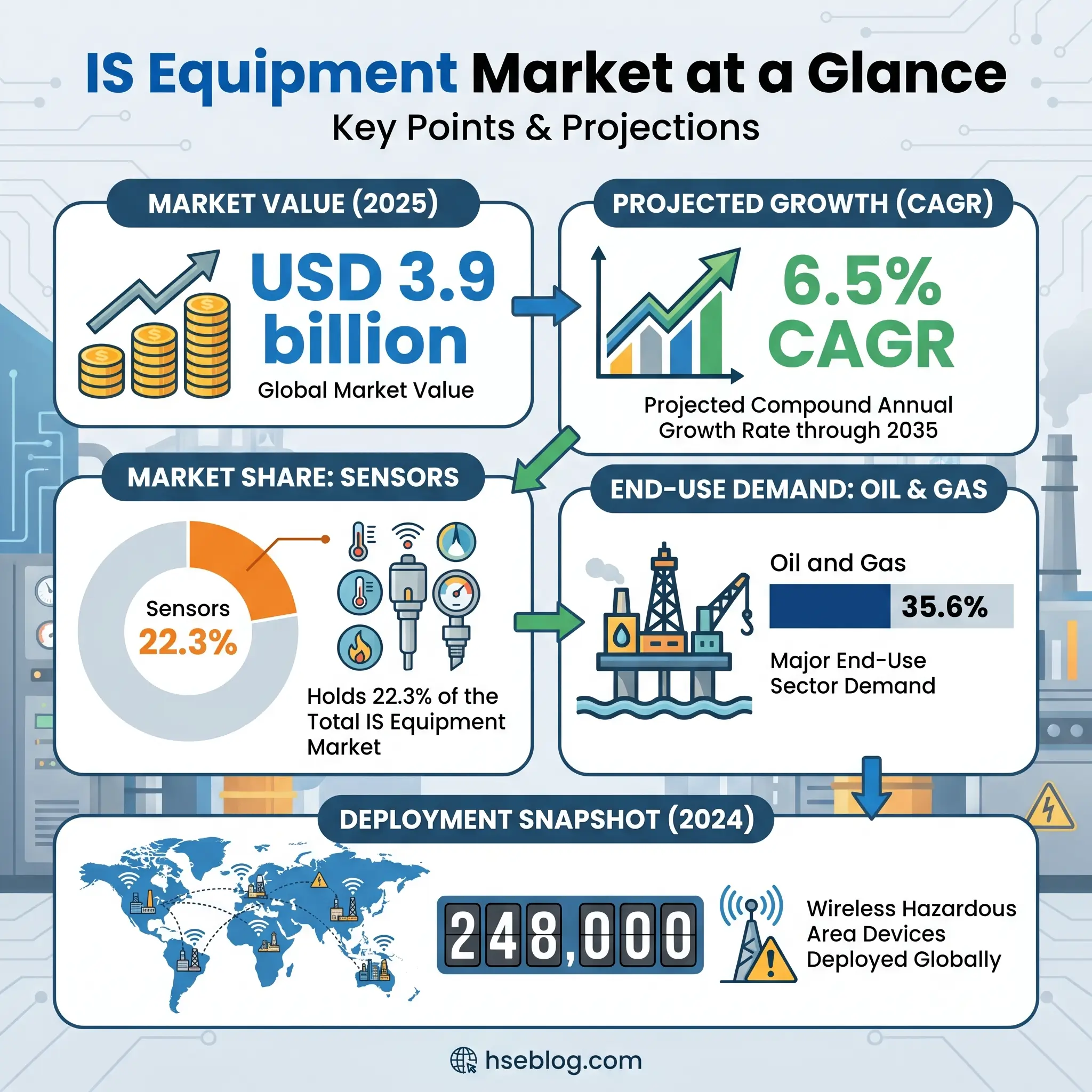
That principle — eliminating the ignition source rather than surviving the blast — defines intrinsically safe equipment and separates it from every other protection method used in hazardous environments. Across the chemical processing, oil and gas, pharmaceutical, mining, and grain handling industries, IS equipment protects workers in atmospheres where a single spark measured in microjoules can trigger catastrophic overpressure events. The global IS equipment market reached approximately USD 3.9 billion in 2025 and is projected to nearly double to USD 7.4 billion by 2035, growing at a compound annual growth rate of 6.5%. That growth reflects an operational reality: as process instrumentation becomes denser and digital transformation pushes more devices into classified areas, the demand for equipment that is inherently safe — not just protectively enclosed — accelerates. This article breaks down how intrinsic safety works at the circuit level, explains the classification systems that determine when you need it, compares it directly with explosion-proof alternatives, and provides a practical selection framework you can apply on your next project.
How Intrinsically Safe Equipment Prevents Explosions in Hazardous Environments
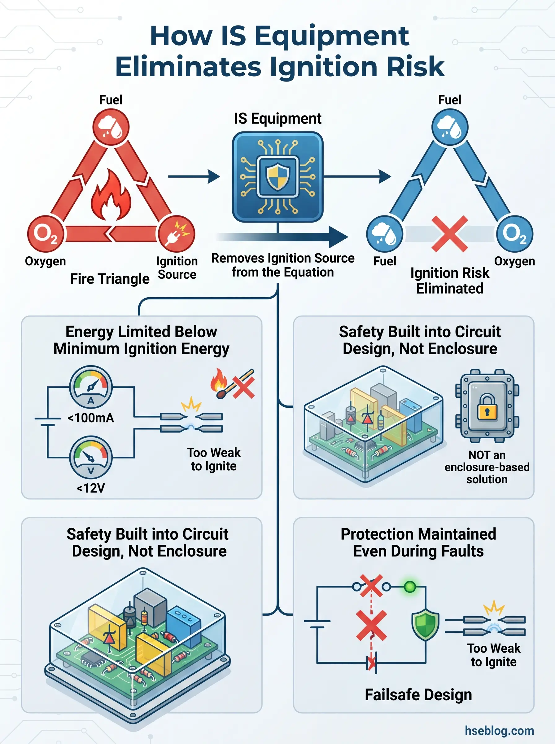
Every explosion requires three elements to converge: a fuel source (flammable gas, vapor, or combustible dust), an oxidizer (typically atmospheric oxygen), and an ignition source delivering sufficient energy to initiate combustion. Remove any one element and the explosion cannot occur. Most protection philosophies in hazardous area engineering accept that fuel and oxygen will be present and focus on managing the ignition source — but they take fundamentally different approaches to that management.
Explosion-proof equipment, known as flameproof under IEC terminology, accepts that an ignition may occur inside its heavy cast enclosure and is engineered to contain the resulting flame front, cooling exhaust gases through precision-machined flame paths so they cannot propagate into the surrounding atmosphere. Pressurized enclosures maintain positive internal pressure to exclude the flammable atmosphere entirely. Increased safety equipment tightens manufacturing tolerances to reduce the probability of sparks or hot surfaces.
Intrinsic safety takes a different path entirely. Rather than containing or excluding, IS circuits are designed so the maximum electrical and thermal energy available at any point — under both normal operation and defined fault conditions — remains below the minimum ignition energy (MIE) of the specific gas or dust group. Voltage is typically limited below 29V DC, current below 300 mA, and total power below 1.3W. Surface temperatures are controlled within defined temperature classes, from T1 (450°C) down to T6 (85°C), with T4 at 135°C being the most common threshold for IS field devices in chemical processing environments.
Watch For: The distinction matters operationally. A technician can troubleshoot a live IS transmitter in a Zone 1 area with a certified IS multimeter. That same task on an explosion-proof junction box requires full power isolation, a hot-work permit, and gas testing — turning a 15-minute job into a two-hour procedure.
What makes IS unique among protection methods is that the safety is inherent to the circuit’s electrical parameters. It does not depend on gaskets holding, flame paths remaining clean, or enclosure bolts maintaining torque. The physics of the circuit itself prevents ignition. That characteristic is why IS remains the only protection method certified for continuous use in Zone 0 — the most dangerous classification, where an explosive atmosphere is present continuously or for long periods.
How Intrinsic Safety Works: The Science Behind Energy Limitation
At shift handover last year, an instrument technician asked me a question that cuts to the core of IS design: “If the barrier fails, what stops the explosion?” The answer — and the reason I spent twenty minutes at the whiteboard explaining it — is that IS does not rely on a single barrier. It relies on a system-level energy budget enforced by multiple independent components, each certified to limit a different electrical parameter.
An intrinsically safe circuit restricts three forms of energy that can produce ignition-capable sparks or hot surfaces. Resistive energy is limited by controlling voltage and current — the product of which determines the power available for resistive heating or arc formation at contact points. Capacitive stored energy is controlled by limiting the capacitance permitted in the circuit, because a charged capacitor can discharge its energy in a single, high-current pulse. Inductive stored energy is controlled by limiting the inductance, because an inductor resists changes in current flow and can generate voltage spikes when a circuit is broken.
The devices that enforce these limits are called safety barriers, and they sit at the boundary between the safe area (the control room, the marshalling cabinet) and the hazardous area (the process zone, the tank farm). Two types dominate the industry.
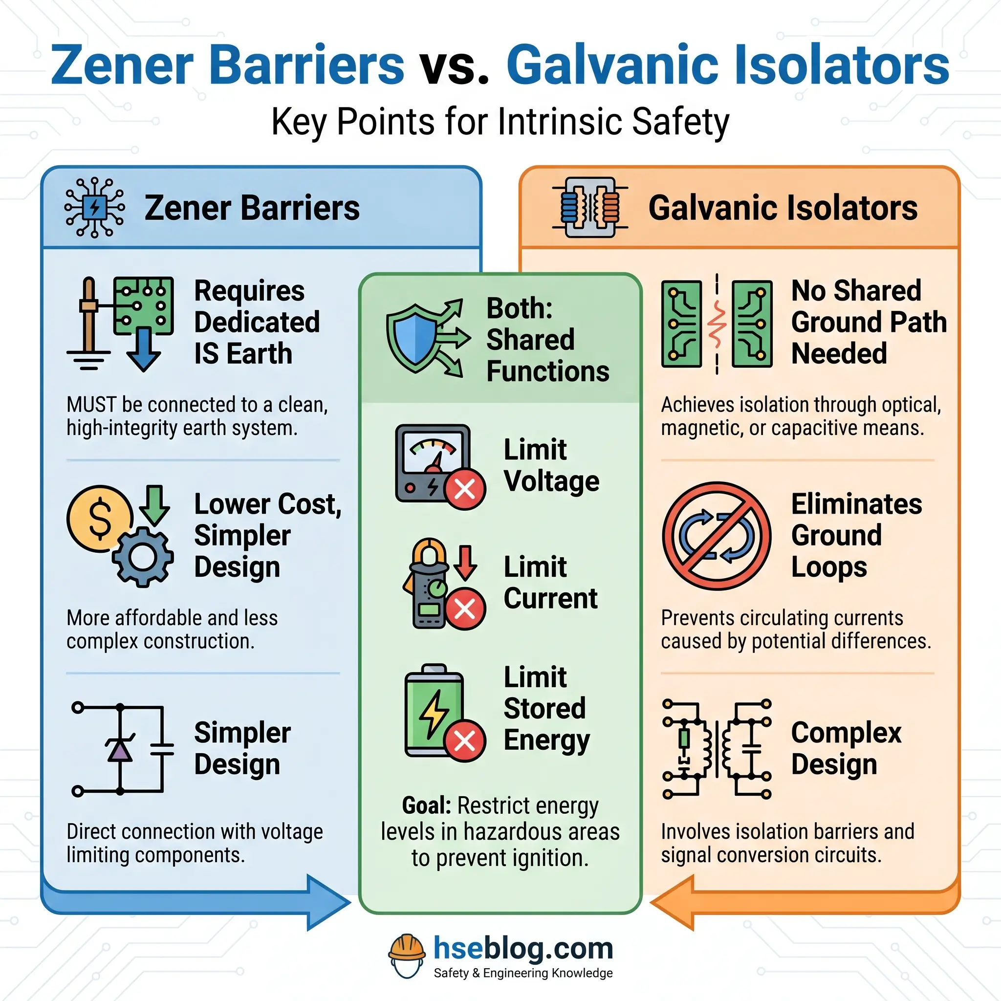
Zener barriers — also called shunt-diode barriers — use a straightforward but effective architecture. Zener diodes clamp the voltage to a safe maximum by shunting excess energy to ground. Series resistors limit the current. A fuse provides overcurrent protection as a final backstop. The design is simple, inexpensive, and well-proven. However, Zener barriers require a high-integrity earth connection — a dedicated IS earth bonded directly to the plant’s main earthing system — because in a fault condition, the barrier shunts energy to ground. If that ground path has high impedance or is missing, the barrier cannot function.
Galvanic isolators use transformers, opto-isolators, or capacitive coupling to transfer the signal between safe and hazardous areas without any direct electrical connection. There is no shared ground path. This eliminates the dedicated IS earth requirement and provides inherent protection against ground-fault-induced voltage differences between the safe and hazardous areas. In facilities where multiple earthing systems create ground potential differences — common in large chemical complexes — galvanic isolators are the safer and more practical choice.
I watched a contractor install Zener barriers on a new analyzer system connected to a reactor train where three separate earthing grids converged. Within six months, ground loop currents were corrupting the 4–20 mA signals and causing false alarms. Replacing the Zener barriers with galvanic isolators resolved the issue without any changes to the field wiring.
One principle that trips up even experienced engineers: certification of individual components does not make a system intrinsically safe. The entire loop — from the power source through the barrier, through every meter of cable (with its distributed capacitance and inductance), to the field device — must be verified as a complete system. IEC 60079-25 specifically addresses this system-level requirement. A certified IS transmitter connected to a certified barrier through unchecked cable can still exceed safe energy limits.
There is an important exception for what the standards call “simple apparatus.” Devices that are purely passive or that generate negligible energy — thermocouples, RTDs, resistive sensors, manual switches, LEDs dissipating under 1.3W — may not require individual IS certification. Their electrical characteristics are inherently too low to present a risk. However, their inclusion in the system must still be documented and the overall loop verified.
Understanding Hazardous Area Classifications: Zones, Divisions, and Classes
The question that determines whether you need intrinsically safe equipment — and which protection level — is not “is this area dangerous?” It is “how often, for how long, and with what substance is an explosive atmosphere present?” Two parallel classification systems answer that question globally, and understanding both is essential because projects routinely cross regulatory jurisdictions.
The IEC/ATEX Zone System
The international system, mandated throughout the EU under the ATEX Directive 2014/34/EU and adopted in most countries outside North America, classifies areas into zones based on the probability and duration of a hazardous atmosphere.
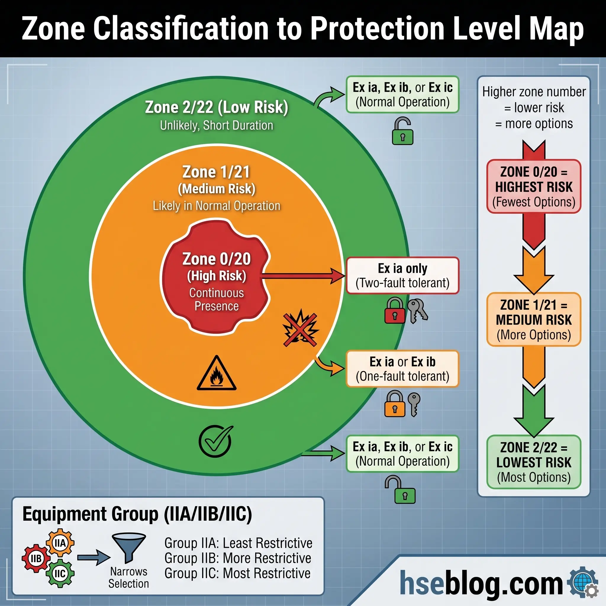
For gases and vapors, three zones apply. Zone 0 defines locations where an explosive gas atmosphere is present continuously, for long periods, or frequently — the vapor space inside a closed process vessel, the interior of a solvent storage tank above the liquid surface. Zone 1 covers areas where an explosive atmosphere is likely to occur during normal operation — the area immediately around a pump seal, a sample point, a loading arm connection during transfer. Zone 2 applies where an explosive atmosphere is not expected during normal operation but may occur briefly — the general area surrounding a flanged pipe joint that could leak, or the zone around a pressure relief valve discharge point.
For combustible dusts, the parallel zones are 20, 21, and 22, with equivalent probability definitions. A grain elevator’s interior during active handling is Zone 20. The area around a bag-dump station is typically Zone 21. General areas in a facility with occasional airborne dust fall under Zone 22.
The North American NEC Class/Division System
The United States and Canada primarily use the National Electrical Code (NEC/NFPA 70) system, which classifies hazardous areas by the type of hazardous material and the probability of its presence.
Class defines the material type: Class I covers flammable gases and vapors, Class II covers combustible dusts, and Class III covers ignitable fibers and flyings. Division indicates probability: Division 1 means the hazardous atmosphere can exist under normal operating conditions, while Division 2 means it exists only under abnormal conditions (equipment failure, container rupture, ventilation system breakdown). NEC Articles 500 through 506 govern the classification process and equipment requirements, with Article 504 specifically addressing intrinsically safe systems.
The NEC also permits use of the Zone system under Articles 505 and 506, and many facilities now adopt a hybrid approach — using Zone classification for new installations while maintaining Division classification for legacy areas.
How Classification Drives IS Equipment Selection
The zone or division classification directly determines the minimum protection level required. Zone 0 (or Division 1 for the most critical applications) demands Ex ia — the highest IS protection level, tolerant of two simultaneous faults. Zone 1 permits Ex ia or Ex ib. Zone 2 allows the use of Ex ic. The same logic applies to dust zones.
Beyond the zone, two additional classification layers refine equipment selection. Equipment Groups categorize hazardous materials by their ignition characteristics: Group IIA (propane, typical hydrocarbons), Group IIB (ethylene, more easily ignited), and Group IIC (hydrogen and acetylene, requiring the strictest protection). Temperature classes — T1 through T6 — define the maximum surface temperature permitted on the equipment, matched against the auto-ignition temperature of the specific substance present.
A transmitter rated Ex ia IIC T4 is certified for use in Zone 0 with hydrogen-group gases and has a maximum surface temperature of 135°C. That single marking string tells a trained engineer exactly where and with what that device can safely operate.
Field Test: Pull any IS device from your instrument store. Read the nameplate marking. Can you decode the protection level, equipment group, and temperature class without referencing a table? If not, every person who handles that equipment needs refresher training on equipment marking interpretation.
Protection Levels Explained: What Do Ex ia, Ex ib, and Ex ic Mean?
During a design review for a new volatile organic compound recovery unit, a project engineer asked why we were specifying Ex ia transmitters for Zone 1 areas when Ex ib would satisfy the minimum requirement. The cost difference across 340 field instruments was significant. My answer came down to fault tolerance and organizational risk appetite — a distinction that competitors’ overviews rarely unpack.
The three IS protection levels are defined by how many independent faults the circuit can sustain while still preventing ignition.
Ex ia provides the highest level of protection. The circuit must remain intrinsically safe under normal operation and with any combination of two simultaneous, independent faults. Testing accounts for both countable faults (component failures) and non-countable faults (wiring short circuits, open circuits). This dual-fault tolerance is why Ex ia is the only IS protection level permitted in Zone 0 — where the explosive atmosphere is present most or all of the time. Under the ATEX system, Ex ia equipment falls under Equipment Category 1G (for gases) or 1D (for dusts), providing the highest Equipment Protection Level: Ga or Da.
Ex ib maintains intrinsic safety under normal operation and with one fault. It provides a single-fault tolerance, which is adequate for Zone 1 environments where the explosive atmosphere is likely but not continuous. The ATEX Equipment Category is 2G (gases) or 2D (dusts), corresponding to Equipment Protection Level Gb or Db. Most permanent process instrumentation in Zone 1 chemical processing environments uses Ex ib as the baseline — unless a site’s own risk assessment drives the specification higher.
Ex ic is safe only under normal operating conditions, with no fault tolerance. If a component fails or a wiring fault occurs, the circuit may exceed safe energy limits. This level is restricted to Zone 2, where an explosive atmosphere is unlikely during normal operation and, if it occurs, exists only briefly. ATEX Category 3G/3D, Equipment Protection Level Gc/Dc.
The IECEx certification system uses Equipment Protection Levels (EPLs) — Ga, Gb, Gc for gases and Da, Db, Dc for dusts — to express the same concept in a format that maps across different protection methods, not just intrinsic safety. An EPL of Ga, for example, means “very high” protection regardless of whether that protection comes from intrinsic safety, encapsulation, or another method.
Back to the design review: we chose Ex ia for the VOC recovery unit not because Zone 1 required it, but because the process stream contained IIC-group solvents with exceptionally low minimum ignition energies, and the instruments were in locations where cable damage from mechanical handling was a realistic ongoing risk. Dual-fault tolerance provided margin against a risk profile that single-fault tolerance left uncomfortably thin.
Intrinsically Safe vs. Explosion-Proof Equipment: Which Do You Need?
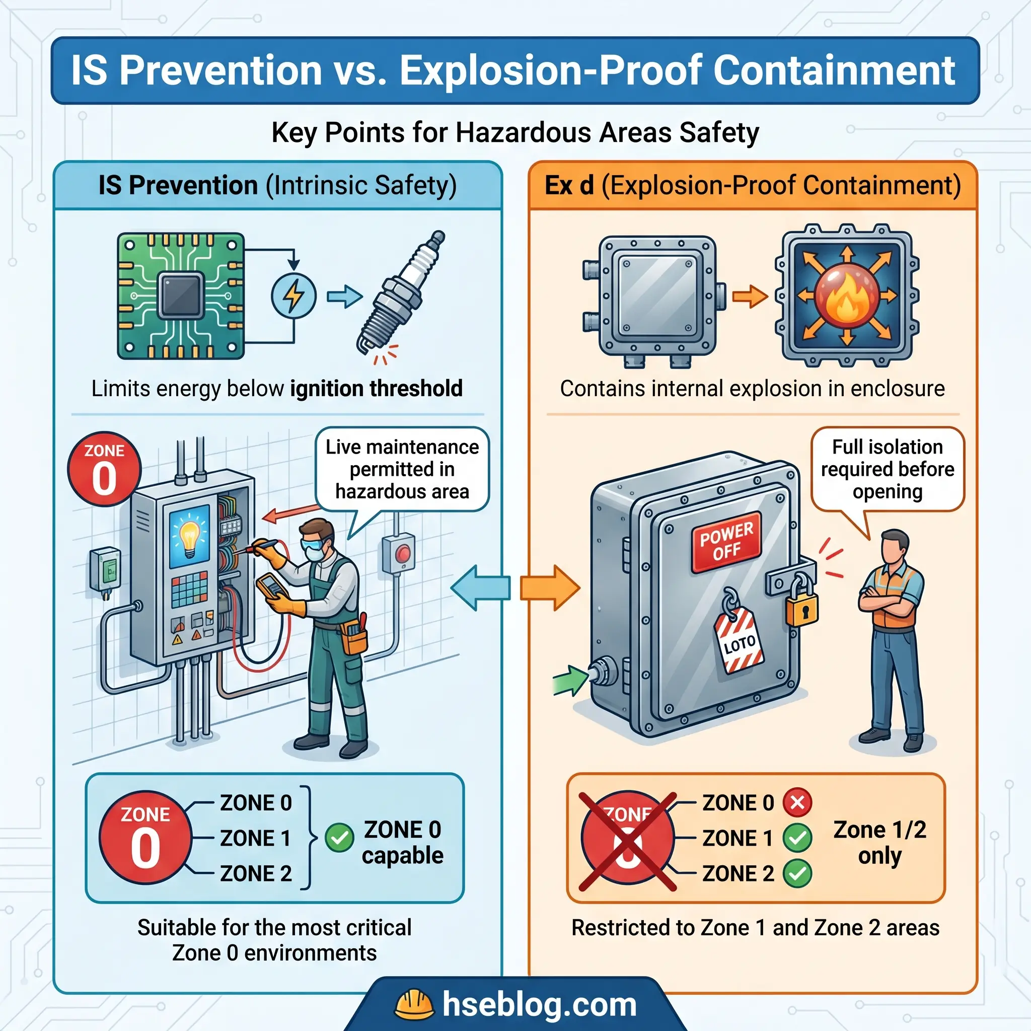
A colleague who transferred from a heavy civil project to our chemical facility described explosion-proof junction boxes as “armored safes bolted to pipe racks.” That mental image captures the philosophical divide. Explosion-proof — or flameproof, as IEC 60079-1 designates it — accepts that an ignition may occur inside the enclosure and engineers the enclosure to contain and cool the resulting flame. Intrinsic safety prevents the ignition from ever happening by ensuring the circuit cannot produce a competent spark or sufficient thermal energy.
This philosophical difference drives every practical distinction between the two methods.
Power and application range. IS equipment is inherently limited to low-power applications — sensors, transmitters, communication devices, portable gas detectors, and similar instrumentation. The energy limits that make IS safe also make it incapable of running a motor, powering a lighting fixture, or driving a solenoid valve. Explosion-proof enclosures accommodate high-power equipment: motors, switchgear, lighting, large junction boxes, and control panels. If the application requires more than approximately 1.3W, IS is not an option.
Maintenance access. This is the single largest operational advantage of IS. Under defined conditions outlined in IEC 60079-14 and IEC 60079-17, technicians can perform live maintenance on IS circuits in hazardous areas — calibrating a transmitter, swapping a sensor, testing a loop — without isolating power, without gas testing, and without a hot-work permit. Explosion-proof equipment demands full de-energization, mechanical isolation, gas clearance testing, and in many jurisdictions a permit-to-work before the enclosure can be opened. On a reactor train with 200 instruments, the cumulative maintenance time difference over a turnaround is measured in days, not hours.
Weight and portability. A portable IS gas detector weighs under 500 grams. An explosion-proof equivalent — if one existed for the same function — would weigh several kilograms. IS radios, cameras, flashlights, and personal monitors are handheld devices. Explosion-proof equipment requires structural mounting and cable gland connections.
Zone suitability. IS (Ex ia) is the only electrical protection method permitted for continuous use in Zone 0. Explosion-proof equipment is limited to Zone 1 and Zone 2. For permanent installation inside vessels, tanks, or other Zone 0 environments, IS is not just preferable — it is the only certified option.
Installation cost. IS wiring is standard instrument cable (with certified capacitance and inductance values), terminated at standard barrier-equipped marshalling cabinets. Explosion-proof installations require heavy conduit, threaded fittings, certified cable glands, and flameproof enclosures — all significantly more expensive to purchase, install, and inspect.
Audit Point: Check how your site documents the decision between IS and explosion-proof for each application. OSHA 29 CFR 1910.307 and NEC Article 504 require that the protection method be appropriate for the classified location. If there is no documented justification, the selection is audit-vulnerable.
The decision factors that should drive your choice: the zone or division classification of the installation location, the gas or dust group present, the power requirement of the equipment, whether live maintenance is operationally necessary, portability requirements, and the total lifecycle cost including installation, inspection, and maintenance over the equipment’s service life.
Industries and Applications That Require Intrinsically Safe Equipment
Oil and gas operations account for the largest share of IS equipment deployment — approximately 35.6% of the global market in 2025. Upstream drilling platforms rely on IS-certified gas detectors, pressure transmitters, temperature sensors, and communication radios across multiple zone classifications. Refineries use IS instrumentation throughout their process units, particularly around distillation columns, heat exchangers, and hydrocarbon storage. Pipeline monitoring systems deploy IS-certified wireless transmitters in remote locations where maintenance access is limited and the ability to operate without power isolation is essential. During marine fuel transfer operations, the U.S. Coast Guard mandates IS-rated radios — a requirement that catches vessel operators off guard when they discover their standard marine VHF sets are not IS-certified.
Chemical processing facilities — the environment I work in daily — present some of the most demanding IS requirements because the range of hazardous substances is broader than in most other industries. A single facility may process hydrogen (Group IIC, requiring the highest IS rating), ethylene (Group IIB), and standard hydrocarbon solvents (Group IIA) across different process units. Volatile organic compounds with flash points below ambient temperature create near-continuous Zone 1 conditions around sampling points, analyzer shelters, and drum-filling stations. Reactor monitoring instrumentation frequently requires Ex ia protection because the instruments sit inside or immediately adjacent to vessels classified as Zone 0.
In pharmaceutical manufacturing, the hazard profile is less obvious but no less real. Fine active pharmaceutical ingredient (API) powders create combustible dust atmospheres during milling, blending, and tablet compression. Solvent-based coating processes and granulation operations introduce flammable vapor hazards that require Zone 1 classification around spray chambers and drying equipment. A colleague working in a large-scale pharmaceutical facility described finding a non-IS-rated barcode scanner being used inside a solvent recovery room — the kind of overlooked portable device that bypasses area classification controls entirely.
Mining — particularly coal mining — holds a historical significance in the IS story. The development of intrinsic safety as a protection concept was driven by devastating coal mine explosions in the early 1900s, where electrical signaling equipment ignited methane-air mixtures in underground galleries. Today, IS-certified methane detectors, communication systems, and cap lamps are standard underground equipment in virtually every coal-producing jurisdiction.
Grain handling and food processing facilities face combustible dust hazards that are frequently underestimated. Flour, sugar, starch, and powdered milk can form explosive atmospheres when dispersed in air within enclosed spaces — elevator legs, conveyor transfer points, silo headspaces. The concentration of explosive dust incidents in this industry — including major events that have reshaped regulatory frameworks — makes IS instrumentation in classified zones a non-negotiable requirement.
Two less commonly discussed applications deserve attention. Wastewater treatment plants with enclosed anaerobic digesters generate methane concentrations that can reach explosive levels. The headspace of a covered digester is typically classified as Zone 0 or Zone 1, requiring IS-rated level transmitters, gas detectors, and temperature probes. And confined space entry across all industries relies heavily on IS-certified portable equipment — gas detectors, communication devices, and lighting — because the entering worker is placing themselves inside an environment where atmospheric conditions may be unknown or variable.
Sensors hold a dominant position in the IS equipment market, accounting for a 22.3% share in 2025. That dominance reflects the fundamental fit between IS and sensing applications: sensors are inherently low-power, often located in the most hazardous process locations, and require frequent calibration — all characteristics that favor intrinsic safety over any other protection method.
Certification Standards and Regulatory Frameworks for Intrinsically Safe Equipment
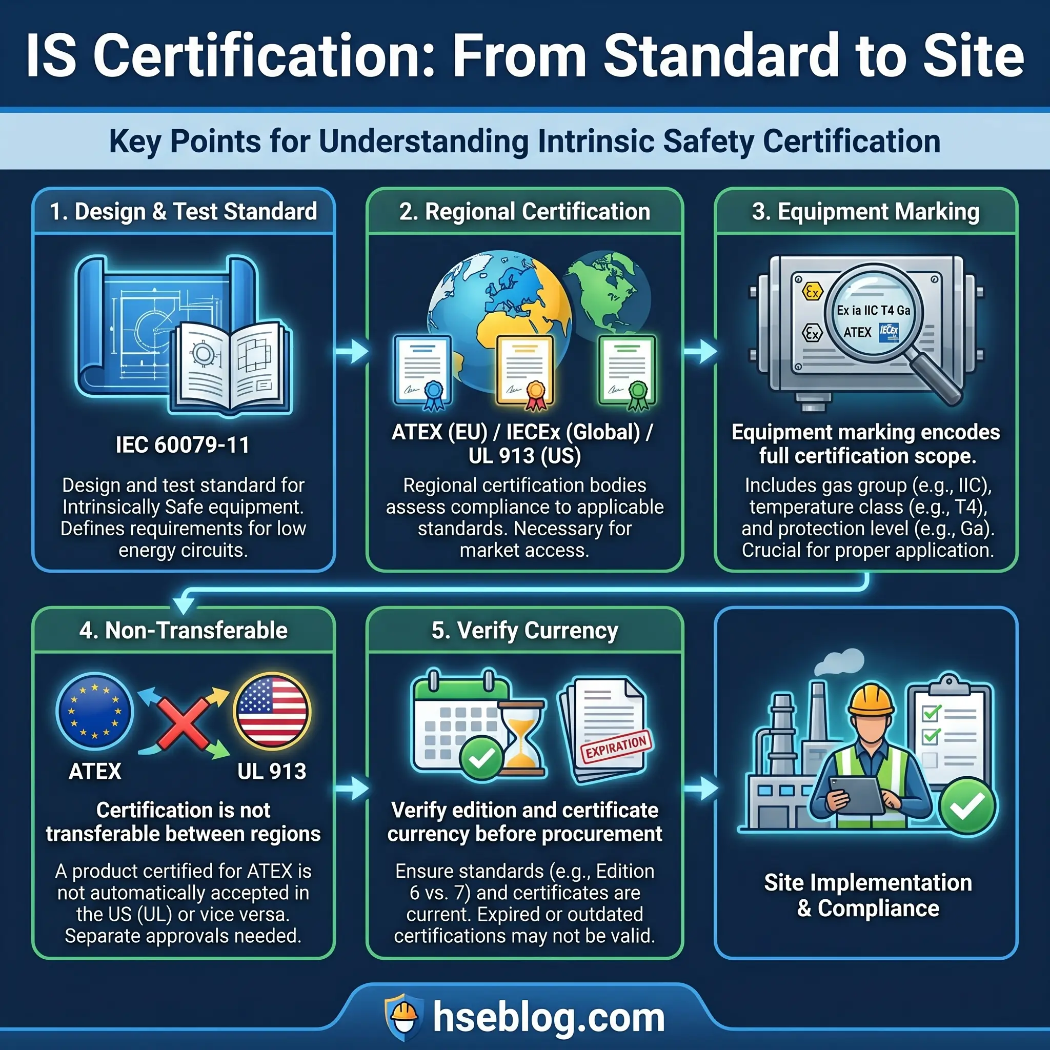
The standard that governs IS equipment design, construction, and testing worldwide is IEC 60079-11. The current edition — Edition 7, published in January 2023 — introduced 45 major technical changes from Edition 6, affecting everything from component fault assessment to creepage and clearance requirements. Manufacturers and end users are still actively transitioning to Edition 7. If you are procuring new IS equipment, verifying which edition the manufacturer’s certification was tested against is not optional — the technical changes are substantive enough to affect interoperability and safety integrity.
IEC 60079-11 does not operate in isolation. IEC 60079-0 provides the general requirements applicable to all explosion-protected equipment, forming the foundation that IEC 60079-11 builds upon with IS-specific requirements. IEC 60079-14 governs electrical installation design, selection, and erection — critically, it requires documented proof of intrinsic safety before commissioning any IS circuit. IEC 60079-17 specifies inspection and maintenance requirements throughout the equipment’s operational life. IEC 60079-25 addresses intrinsically safe systems — the interconnection of IS apparatus, associated apparatus, and cabling as a verified whole.
In the European Union, the ATEX Directive 2014/34/EU makes certification mandatory for any equipment intended for use in potentially explosive atmospheres. ATEX is not a certification standard itself — it is a regulatory directive that requires equipment to be tested and certified against harmonized standards (including IEC 60079-11) by a Notified Body. A device bearing the ATEX marking has been assessed for conformity and carries a certificate traceable to a specific Notified Body.
The IECEx system provides an international certification framework recognized in over 30 countries. An IECEx Certificate of Conformity (CoC) can be verified online, providing procurement teams with a way to confirm that a device’s certification is current and that its test report was issued by an accredited laboratory. While IECEx is gaining international traction, it is not automatically accepted everywhere — and this creates a critical procurement pitfall.
North America operates under its own certification ecosystem. UL 913 and FM 3610 are the primary standards used by Nationally Recognized Testing Laboratories (NRTLs) — UL, FM Global, CSA, and Intertek — to test and approve IS apparatus. The NEC (NFPA 70) governs installation: Article 500 defines classification, Article 504 covers intrinsically safe systems, Article 505 addresses the Zone classification system, and Article 506 covers Zone classification for dusts and fibers. OSHA 29 CFR 1910.307 provides the federal regulatory authority.
A device certified under ATEX is not automatically accepted under NEC/UL requirements. A device with an IECEx certificate does not satisfy ATEX without additional assessment by an EU Notified Body. Each regional certification requires independent testing and approval. I have seen procurement teams purchase IS equipment certified only under IECEx for installation in a facility subject to ATEX requirements — the devices sat in a warehouse for months while the manufacturer arranged EU certification.
Reading IS Equipment Markings
The marking string on an IS device encodes its entire certification scope. Under IEC/ATEX, a marking such as Ex ia IIC T4 Ga tells you: Ex = explosion-protected equipment; ia = protection level (two-fault tolerant); IIC = equipment group (suitable for hydrogen/acetylene atmospheres); T4 = temperature class (maximum surface temperature 135°C); Ga = equipment protection level (very high, suitable for Zone 0). Under the NEC system, IS CL I Div 1 GP ABCD T5 indicates: IS = intrinsically safe; Class I = gases/vapors; Division 1 = normal-condition hazard; Groups A through D = gas groups; T5 = temperature class (100°C maximum).
Every person who selects, installs, inspects, or maintains IS equipment must be able to read these markings without hesitation.
How to Select the Right Intrinsically Safe Equipment for Your Application
Selecting IS equipment is not a catalog exercise. It is a system engineering task that begins with the classified area and works backward through protection levels, equipment groups, temperature classes, barrier selection, and entity parameter verification. Missing any step can result in a non-compliant installation or — worse — one that appears compliant on paper but does not provide the protection its marking claims.
Step 1: Verify the hazardous area classification. Confirm the zone or division, the gas or dust group, and the temperature class of the specific location where the equipment will be installed. This information comes from the facility’s area classification drawings, which should be current and signed off by a competent person. Never assume a classification. I have encountered situations where a field instrument was replaced like-for-like, but the area classification had been revised since the original installation — the new classification required a higher protection level that the replacement device did not meet.
Step 2: Determine the required protection level. Zone 0 demands Ex ia. Zone 1 requires Ex ia or Ex ib. Zone 2 permits Ex ic. For dust zones, the parallel requirements apply (Zone 20 → ia, Zone 21 → ia/ib, Zone 22 → ic). Your site’s risk assessment may specify a higher protection level than the minimum — document the basis either way.
Step 3: Select IS-certified equipment with appropriate group and temperature ratings. The equipment’s certified gas or dust group must cover the substances present. Group IIC equipment is suitable for IIA, IIB, and IIC atmospheres — it is the most universally applicable. The temperature class must ensure the maximum surface temperature stays below the auto-ignition temperature of the substance, with the appropriate safety margin built into the T-class system.
Step 4: Choose the barrier type. Zener barriers for simple, single-loop installations with a verified high-integrity IS earth. Galvanic isolators for complex installations, sites with multiple earthing systems, or where ground-loop interference is a concern. In practice, galvanic isolators have become the default in new chemical process installations because they eliminate the IS earth dependency and provide better signal integrity.
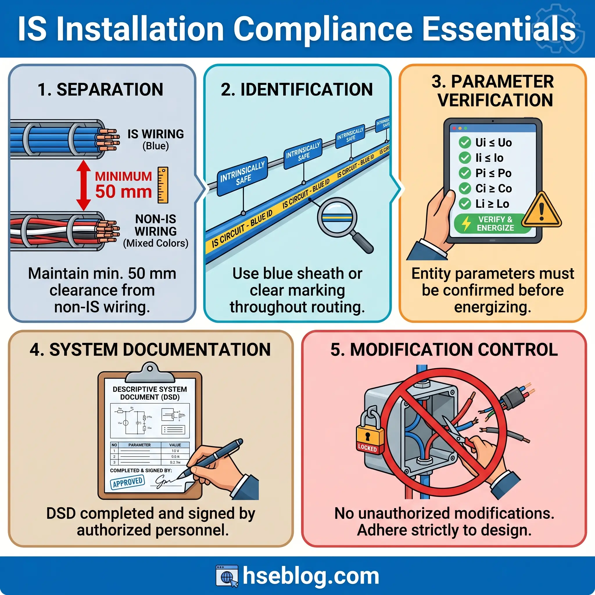
Step 5: Verify entity parameters. This is the step most frequently done inadequately. The associated apparatus (barrier) publishes its safety output parameters: Voc (maximum open-circuit voltage), Isc (maximum short-circuit current), Ca (maximum permitted capacitance), and La (maximum permitted inductance). The field device publishes its maximum input parameters: Vmax, Imax, Ci (internal capacitance), and Li (internal inductance). The system is safe only if: Voc ≤ Vmax, Isc ≤ Imax, Ca ≥ Ci + Ccable, and La ≥ Li + Lcable. The cable’s capacitance and inductance per unit length, multiplied by the cable run distance, must be included in the calculation.
Step 6: Document the complete system. IEC 60079-14 requires that proof of intrinsic safety be documented before commissioning. The Descriptive System Document must show every component, every cable parameter, and the entity parameter verification for each loop. This documentation is not a nice-to-have — it is the evidence that the system has been designed as a verified intrinsically safe installation.
The Fix That Works: Create a standardized IS loop verification sheet that instrument technicians complete for every new IS circuit. Include fields for the barrier model, field device model, cable type, cable length, calculated Ccable and Lcable, and the entity parameter comparison. Have the responsible electrical engineer sign off. This catches parameter mismatches before commissioning — not during an audit three years later.
Step 7: Plan for lifecycle inspection. IEC 60079-17 requires inspection at commissioning and at defined periodic intervals based on installation type and environmental conditions. The inspection plan should be specified during the design phase, not developed after handover.
Installation, Inspection, and Maintenance Requirements
Proper IS system performance depends on installation practices that many sites treat as optional refinements rather than safety-critical requirements. The principle underlying every installation rule is that the intrinsic safety of a circuit depends on total system parameters — cable capacitance, cable inductance, separation from non-IS circuits — not just on certified device ratings.
IS wiring must be physically separated from non-IS wiring. NEC Article 504 specifies a minimum separation of 50 mm (approximately 2 inches) when cables run in separate raceways or cable trays without a grounded metal partition. When a grounded barrier separates the circuits, no additional spacing is required. In practice, many facilities adopt a blanket policy of routing IS cables in dedicated trays identified with blue marking — a visual segregation that simplifies inspection and prevents future wiring additions from compromising separation distances.
The blue color coding is more than convention. IS circuits require distinctive identification throughout their routing — at the marshalling cabinet, along the cable tray, at the field junction box. Blue sheathing, blue identification tags, and blue terminal strips are the industry standard. Every cable in the system must have certified capacitance and inductance values per unit length, published by the cable manufacturer, and these values must be used in the entity parameter calculations. A cable substitution — even with a cable that appears physically identical — can invalidate the loop’s IS certification if its electrical parameters differ.
Pre-commissioning verification is a formal step, not a walkdown. The responsible engineer must verify that every IS loop matches its Descriptive System Document: correct barrier installed, correct field device, correct cable type and routing, correct terminations, correct identification, and entity parameters confirmed. IEC 60079-14 makes this verification a mandatory prerequisite for energizing an IS circuit.
Once operational, IS equipment requires ongoing inspection to detect damage, deterioration, or unauthorized modifications. On a facility walkdown last quarter, I found a field junction box where a maintenance technician had added a non-IS-rated surge protector across a 4–20 mA loop “to protect the transmitter during lightning season.” The device added unmeasured capacitance to the circuit, potentially exceeding the barrier’s Ca limit. The modification was well-intentioned and completely non-compliant. IEC 60079-17 establishes that users must not tamper with, repair, or modify IS equipment — only manufacturer-authorized servicing is permitted. This rule is absolute.
The total installed base of certified hazardous area devices globally exceeded 890,000 units in 2024, and deployment of wireless-enabled hazardous area devices grew by 18% in that same year, reaching 248,000 operational units worldwide. As this installed base grows, the inspection and maintenance burden grows proportionally — and the consequences of deferred inspection become more severe.
What Does the Future of Intrinsic Safety Look Like?
For decades, the practical limitation of intrinsic safety was bandwidth. IS circuits could carry a 4–20 mA analog signal or a low-speed digital protocol like HART — enough for a single process variable, but nowhere near what modern process automation demands. That limitation is ending.
Ethernet-APL (Advanced Physical Layer) is the single most significant development in hazardous area instrumentation in the past twenty years. Based on IEEE 802.3cg (10BASE-T1L), Ethernet-APL delivers 10 Mbit/s Ethernet communication over a two-wire cable spanning up to 1,000 meters — with integrated intrinsic safety protection for Zone 0 and Zone 1 installations. For the first time, a field device in a classified area can communicate at full Ethernet speed using the same protocol architecture as the plant’s IT network. Major manufacturers including Pepperl+Fuchs, Endress+Hauser, and ABB are releasing certified Ethernet-APL field switches and devices, and the standardization of the SPE (Single Pair Ethernet) connector under IEC 63171-7 in 2025 is accelerating device ecosystem growth expected through 2026.
Alongside Ethernet-APL, a new technical specification — IEC TS 60079-47, designated 2-WISE (2-Wire Intrinsically Safe Ethernet) — simplifies the intrinsic safety verification process for these connections. Traditional IS verification requires detailed entity parameter calculations for every loop. 2-WISE defines a standardized power and communication framework that eliminates the need for individual entity parameter matching at each connection point, dramatically reducing engineering effort for large-scale Ethernet-APL deployments. For a facility with hundreds of IS field instruments, this simplification translates directly into reduced design hours and faster commissioning.
IoT-enabled IS devices are pushing monitoring capabilities beyond traditional process variables. Cloud-connected IS sensors now deliver real-time asset health data — vibration profiles, corrosion rates, fugitive emission readings — from hazardous areas directly to maintenance planning systems. Predictive maintenance algorithms fed by IS-certified wireless sensors can identify developing failures in rotating equipment weeks before a breakdown, in locations where manual data collection previously required confined space entry or elevated work.
Intrinsically safe smartphones and tablets are also changing how work is performed in classified areas. Purpose-built IS-certified devices and certified protective cases for select consumer models enable digital permit-to-work systems, electronic inspection checklists, real-time procedure display, and photo documentation inside Zone 1 and Zone 2 environments. The practical impact is substantial: a technician performing an IS loop check can pull up the loop diagram, record measurements, photograph the installation, and close the work order — all on a single device that is certified for the atmosphere surrounding them.
The ongoing transition to IEC 60079-11 Edition 7, with its 31 major technical changes affecting both manufacturers and end users, means that procurement teams and engineering departments must verify certification edition compatibility. Equipment certified under Edition 6 remains valid for its certified scope, but new designs and recertifications increasingly reflect Edition 7 requirements.
Frequently Asked Questions
The circuit parameters that define intrinsic safety have not changed since the discipline’s origins in early twentieth-century mining. What has changed — and is accelerating — is the range of capability those constrained parameters can deliver. Ethernet-APL is bringing Zone 0 field devices into the same digital architecture as enterprise IT systems. 2-WISE is removing the engineering burden that previously made large-scale IS deployments labor-intensive to verify. IoT-enabled IS sensors are feeding predictive maintenance systems with data that was previously inaccessible without entering hazardous areas.
For the professionals responsible for specifying, installing, and maintaining this equipment, the core obligation remains unchanged: verify the complete system, not just the device. An IS transmitter certified to Ex ia IIC T4 means nothing if the barrier’s entity parameters do not accommodate the cable run, if the wiring shares a tray with power circuits, or if a well-meaning technician adds an uncertified component to the loop. The physics of energy limitation is unforgiving. It does not care about intentions — it cares about microjoules, picofarads, and microhenries.
Whether you are designing a new classified area installation, auditing an existing one, or procuring your facility’s next generation of field instruments, the decision framework is consistent: classify the area, determine the protection level, verify the system parameters, and document everything. The equipment does its job when the system behind it is engineered correctly.