

TL;DR — the numbers that anchor every decision:
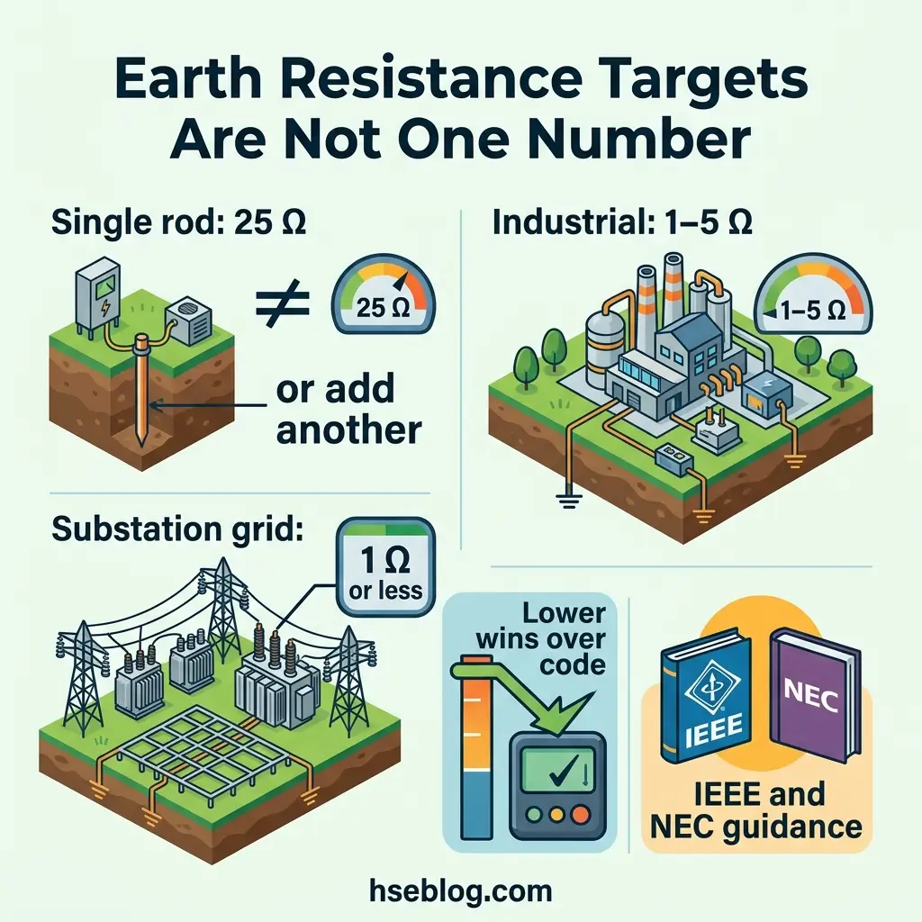
- ≤25 Ω — the NEC value for a single made electrode, and the most misread figure in the field. It is not a universal system target (NFPA 70, 2023 edition, US).
- 1–5 Ω — the range IEEE treats as suitable for most industrial and commercial installations (IEEE 142, “Green Book”).
- ≤1 Ω — the value typically engineered for substation grounding grids (IEEE 80).
- 2,070 — workplace deaths involving electricity in the US between 2011 and 2024, with about 70% in non-electrical occupations (BLS and OSHA data compiled by ESFI, 2026).
An earthing (or grounding) system gives fault current a low-impedance path back to its source, so protective devices trip before exposed metalwork stays live. Testing measures that path — chiefly earth electrode resistance and bonding continuity — to confirm it will actually carry fault current when a fault happens. Installation and testing both follow IEC, IEEE, and national codes.
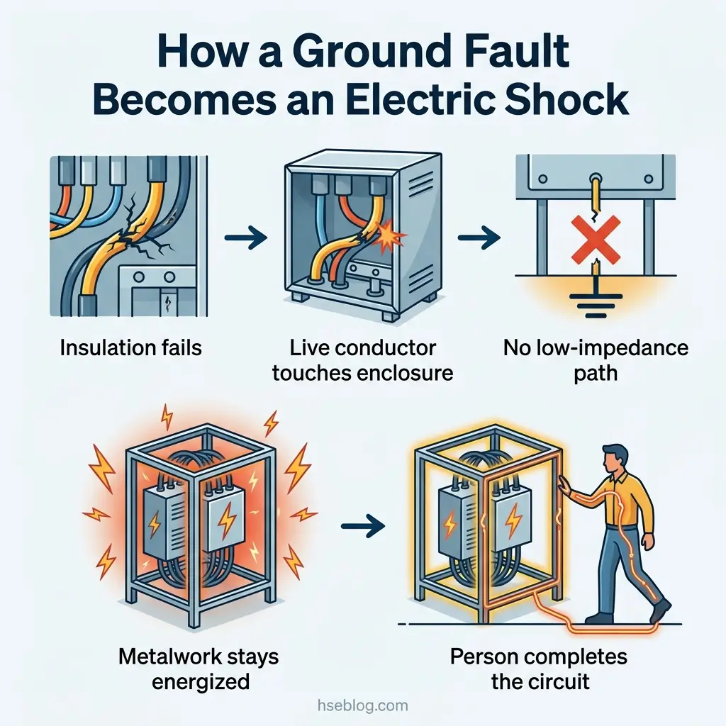
Electricity killed 2,070 workers in the United States between 2011 and 2024, and roughly 70% of them worked in non-electrical jobs (BLS and OSHA data, compiled by ESFI, 2026). Most never touched a live conductor. The metal they were holding became live because a fault current had nowhere safe to go.
That “nowhere safe to go” is the exact condition earthing and grounding systems exist to remove. This article covers what these systems do, the main earthing system types, how earth resistance and continuity testing actually work, what an acceptable earth resistance value really is, where field tests go wrong, and the compliance and record-keeping obligations that sit behind all of it.
What Earthing and Grounding Systems Actually Do
Strip away the terminology and the job is simple: connect metal that should never be live to the general mass of earth, and give fault current a route that trips protection fast. “Earthing” is the IEC and UK term; “grounding” is the US term. For most practical purposes they describe the same function.
Three separate ideas hide inside the single word, and confusing them is where a lot of testing goes wrong:
- System earthing — how the supply network itself relates to earth (the neutral point of a transformer, for example).
- Protective earthing (bonding) — connecting exposed conductive parts, enclosures, and structural metal so they cannot sit at a dangerous voltage.
- The earth electrode — the physical rod, plate, mat, or foundation connection that ties the installation to soil.
US regulation states the performance requirement plainly. Under OSHA 29 CFR 1910.304(g)(5), the path to ground from circuits, equipment, and enclosures must be “permanent, continuous, and effective” (US general industry; construction sits under 29 CFR 1926.404). Read that as a testing brief. “Permanent” and “continuous” are what continuity testing checks; “effective” is what earth resistance testing checks. A system can look immaculate and still fail all three once corrosion, a broken bond, or dried-out soil enters the picture.
Earthing System Types: TN, TT, and IT — and Why the Type Decides the Test
The international standard for low-voltage installations, IEC 60364-1, classifies earthing arrangements with a two-letter code. The first letter describes the supply’s relationship to earth; the second describes how the installation’s exposed conductive parts are earthed. Get the type wrong and you can test the wrong thing entirely.
| System | How it earths | Fault-clearing path | Testing emphasis |
|---|---|---|---|
| TN-S | Separate neutral (N) and protective earth (PE) throughout | Metallic PE conductor back to source | Loop impedance; PE continuity |
| TN-C-S (PME) | Combined PEN upstream, split at the service | Low-impedance metallic path | Continuity; broken-PEN risk on metalwork |
| TT | Installation uses its own independent electrode | Fault current returns through the earth itself | Earth electrode resistance is critical |
| IT | Supply isolated from earth or via high impedance | First fault tolerated; continuity of supply prioritized | Insulation monitoring; electrode integrity |
The practical reading matters most in TT systems, common in rural supplies and many stand-alone installations. There is no metallic earth return between source and installation, so fault current relies on the electrode and the mass of the earth. A high electrode resistance there is not a paperwork problem — it can mean the protective device never trips. TN systems lean on a metallic path, so continuity and loop impedance carry more weight than the electrode’s raw resistance to soil.
TN-C-S deserves a specific caution. In UK practice this is Protective Multiple Earthing (PME), and a broken PEN conductor upstream can impose a dangerous voltage on all bonded metalwork at once. This is why equipotential bonding is tested so rigorously on these installations, and why the risk has drawn fresh regulatory attention as electric-vehicle charge points multiply on domestic PME supplies.
How Earth Resistance Testing Works: The Main Methods
Testing an earthing system means two different measurements that are often wrongly treated as one. Bonding continuity confirms the metallic connections are intact and low-resistance. Earth electrode resistance confirms the electrode dissipates current into the soil. The methods below, referenced to IEEE 81-2012, target the second.
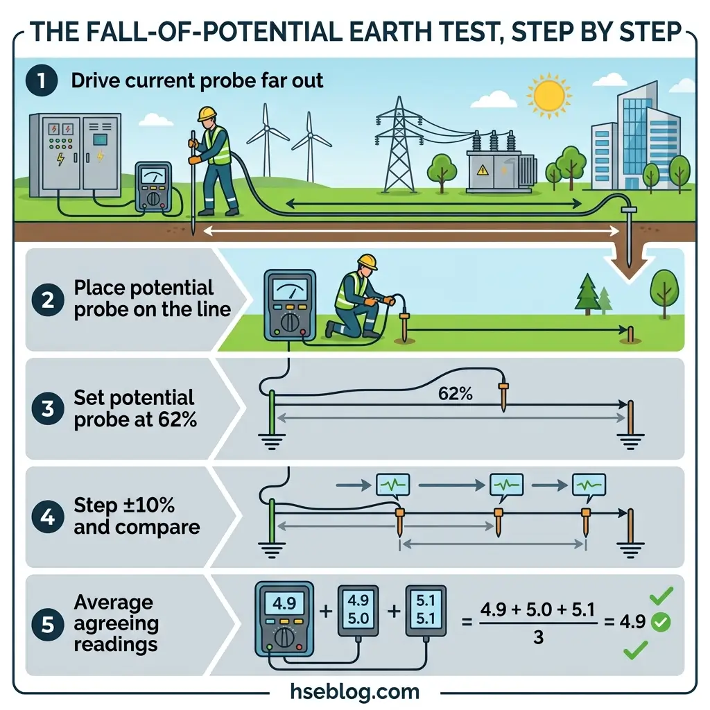
- Fall-of-potential (3-point) method. The reference technique for a standalone electrode. A current probe is driven far out in a straight line, a potential probe sits between it and the electrode, and resistance is read as the potential probe is stepped along the line.
- 62% rule. For uniform soil, the true reading appears with the potential probe at roughly 62% of the distance between the electrode and the current probe. Readings taken at ±10% of that point should agree closely; if they diverge, the current probe is too close and the spacing must grow.
- Selective (clamp-and-probes) method. Uses a current clamp to isolate one electrode in a multi-grounded system without physically disconnecting it — useful in urban and interconnected sites.
- Stakeless (clamp-only) method. Measures loop resistance through parallel paths with no probes and no disconnection. It only works where a genuine parallel return exists; on a single isolated electrode it gives a meaningless value.
- Wenner 4-point method. Measures soil resistivity, not electrode resistance. It is used before installation to design an electrode that will actually meet target.
A recurring judgment call is stakeless versus fall-of-potential. The stakeless clamp is fast and needs no disconnection, which makes it attractive on a live, occupied site. But it silently fails on a single-path electrode, so on TT installations or isolated grounds the fall-of-potential method remains the defensible choice, space permitting.
This article provides general HSE knowledge. Life-critical work such as testing or working on earthing systems near energized equipment must be planned and supervised by a competent person with relevant training, jurisdiction-specific authorization, and a site-specific risk assessment. The information here does not replace that. Recognized routes to competence include NEBOSH and City & Guilds electrical qualifications, IEEE and NETA testing certifications, and regional equivalents.
What Counts as an Acceptable Earth Resistance Value
No single resistance figure is recognized by every authority, which is why the “25 ohms” number causes so much confusion. That value is a specific, narrow US requirement — not a quality target for a whole system.
Here is the misconception, corrected. NEC 250.53(A)(2) says a single rod, pipe, or plate electrode with a resistance to earth above 25 Ω must be supplemented by one additional electrode (US, NFPA 70). It does not say 25 Ω is a good grounding system, and once you install a second electrode the code stops asking for a measured value at all. Treating 25 Ω as the finish line is how installations end up technically compliant and functionally weak.
| Context | Typical target | Source (jurisdiction) |
|---|---|---|
| Single made electrode (US) | ≤25 Ω, or add a second rod | NEC 250.53(A)(2), NFPA 70 (US) |
| Industrial / large commercial | 1–5 Ω | IEEE 142, “Green Book” |
| Substation grounding grid | ≤1 Ω (lower for large stations) | IEEE 80 |
| Sensitive electronics / data | often ≤5 Ω, sometimes ≤1 Ω | Facility specification |
The consistent principle underneath all of these is the one OSHA states and IEC design assumes: resistance must be low enough that protective devices operate quickly and touch voltages stay within safe limits. A specification can always demand a lower value than code; it cannot demand a higher one.
Where Earthing Tests Go Wrong
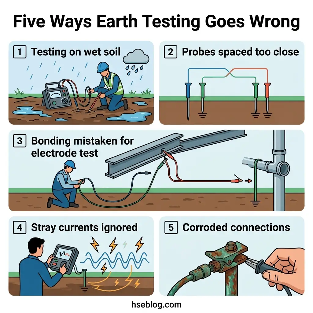
A wrong earth reading is worse than no reading, because it manufactures false confidence. The failure modes below repeat across the published testing literature and field guidance from instrument makers and testing associations.
- Testing on wet ground. Damp soil conducts well and returns a falsely low resistance. Reliable practice measures at least two full days after the last rainfall, so the reading reflects worst-case soil, not best-case weather.
- Probes too close together. If the current probe sits inside the electrode’s “sphere of influence,” the potential probe never reaches true remote earth and the reading is understated. Widening the spacing and re-checking the ±10% agreement is the fix.
- Confusing continuity with electrode resistance. A perfect bond reading tells you nothing about how the electrode meets the soil, and vice versa. Both tests are needed.
- Stray and parallel currents. Buried water pipes, cable sheaths, rebar, and multi-grounded neutrals inject error, especially in dense urban sites. Selective or stakeless methods, or careful isolation, are used to manage this.
- Corroded or painted connections. A rod free of resistance to earth is useless if the clamp to it has corroded. Electrodes and bonds must be free of non-conductive coatings and mechanically sound.
The habit that separates a reliable result from a lucky one is documentation. Record the method, probe distances and bearings, soil condition, weather, and time, so the next test can be repeated on the same basis and a genuine trend — not seasonal noise — is what triggers action.
Compliance, Records, and Re-Test Intervals
Regulatory content here reflects general HSE professional understanding of the cited jurisdictions’ requirements as of 2026. It is not legal advice. Specific compliance questions, enforcement situations, or prosecution risk should be directed to qualified legal counsel in the applicable jurisdiction.
Grounding is one of the few areas where the same underlying duty appears across very different codes. In the US, OSHA enforces it through 29 CFR 1910.304 and 1926.404, which point to the NEC (NFPA 70, Article 250) for the technical detail on bonding and the effective ground-fault current path. In the UK, the framework is BS 7671, with installation earthing guidance in BS 7430. Internationally, IEC 60364 governs the installation and IEC 62305 handles the earthing demands of lightning protection.
- Frequency is risk-based, not one-size-fits-all. Neither a single global re-test interval nor a universal “annual” mandate exists; the interval follows the installation’s environment, condition, and applicable code or scheme.
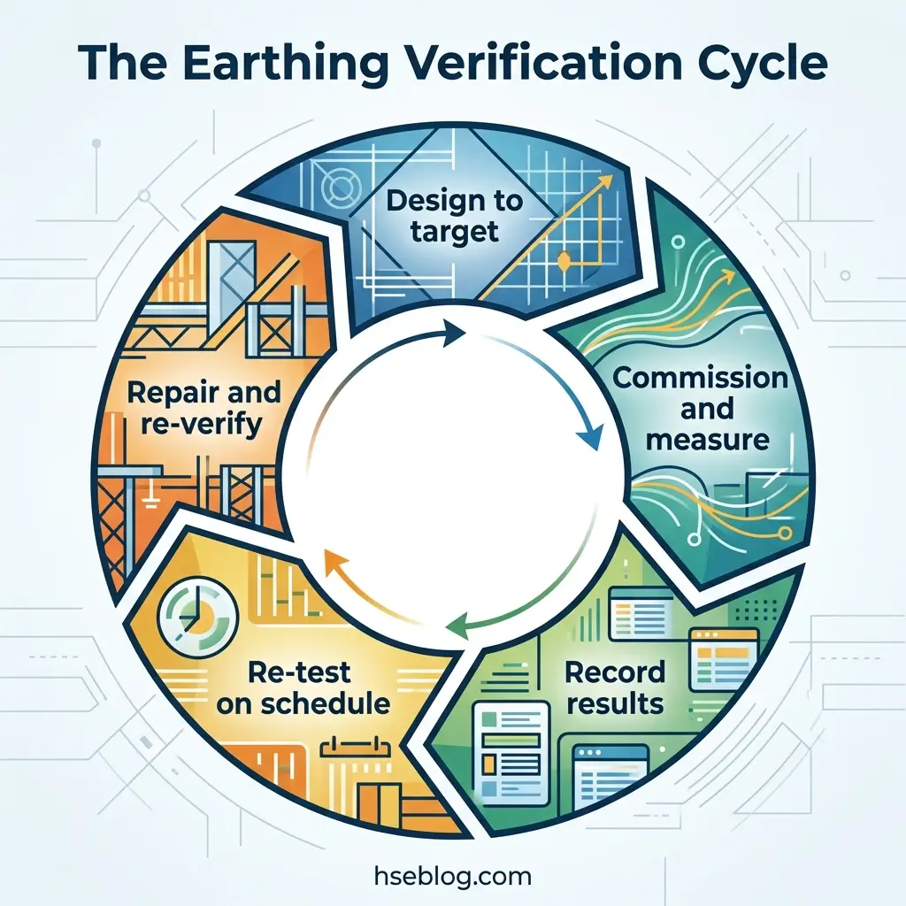
- New installations get commissioned first. Design values are confirmed by measurement before energization, then periodically re-verified.
- Records are the audit trail. Test values, methods, conditions, and instrument calibration status are what an inspector, insurer, or investigator will ask for.
- Environment drives degradation. Corrosion, soil movement, and nearby construction all alter a grounding system over time, which is the whole reason periodic verification exists rather than one-time sign-off.
Where standards specify different thresholds for the same situation, the stricter value governs, and every citation should carry its jurisdiction. A 1 Ω substation target from IEEE 80 and a 25 Ω single-rod trigger from the NEC are not in conflict — they answer different questions for different installations.
Frequently Asked Questions
The One Question Worth Asking Before You Sign Off
Grounding fails quietly. A corroded clamp, a rod that dried out with the summer soil, a bond that was never actually torqued — none of them announce themselves, and none of them show up until fault current arrives and takes the only path left, which may be through a person. The whole point of testing earthing and grounding systems is to find that weakness on a clipboard instead of in an incident report.
So the uncomfortable question is not whether your installation has an earthing system. It is when you last measured one — with the right method for the system type, in worst-case conditions, against the value your installation actually requires rather than the one that was easiest to reach. If the honest answer is “we assume it’s fine,” that assumption is the hazard. Treat the next earth test not as a formality to close out, but as the moment you either confirm the path is there or discover, on your terms, that it isn’t.