
TL;DR
- The clamp is the killer. Closing mould halves can amputate a hand in a single cycle; the operator’s gate and its interlocks are the primary defence, not PPE.
- Interlocks are not isolation. Every serious maintenance injury traces back to someone trusting a guard instead of locking out the machine’s energy.
- Three danger zones, three guarding logics. Mould area, clamp mechanism, and the hot injection unit each demand a different safeguard — one solution does not cover all three.
- The standard set is jurisdictional. OSHA 29 CFR 1910, ANSI/PLASTICS B151.1, and EN ISO 20430 overlap but diverge; know which governs your site.
- Verify guards on a schedule. A defeated interlock or missing top guard is invisible until someone is caught — routine functional checks are the point.
What injection moulding machine safety actually protects against
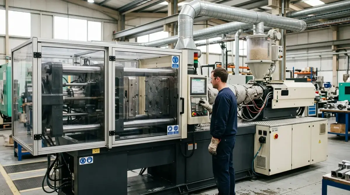
Injection moulding machine safety centres on controlling three lethal zones: the closing mould, the clamp mechanism, and the heated injection unit. The clamp exerts tens to thousands of tonnes of force, capable of crushing or amputating limbs in one cycle. Effective guarding combines interlocked gates, fixed barriers, and lockout/tagout to keep people clear of energy.
Injection moulding is one of the most common plastics processes on earth, which means the machinery sits in thousands of workshops run by teams of very different skill levels. That ubiquity is exactly why the injury record is so consistent — the same failures repeat across sites, sectors, and decades.
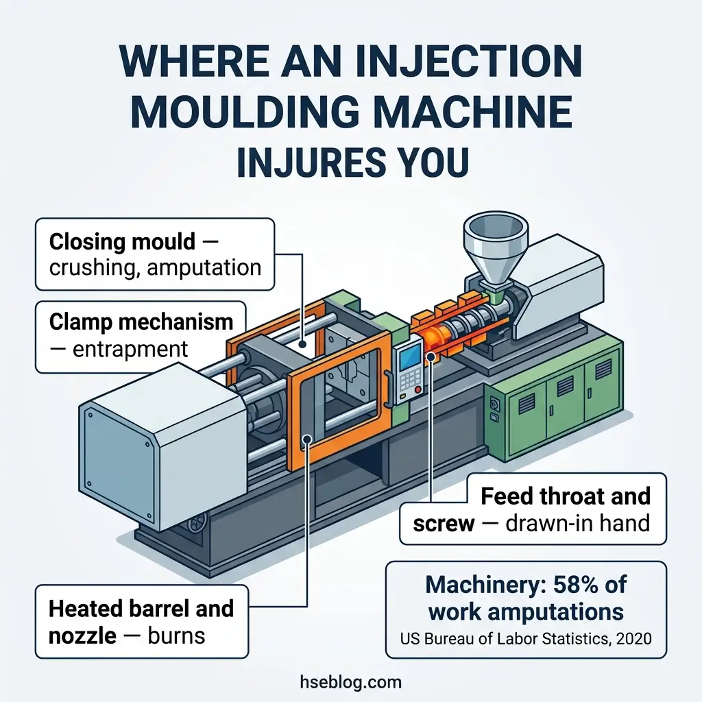
The numbers frame the stakes plainly. In 2018, machinery was involved in 58 percent of work-related amputations, accounting for 3,580 of roughly 6,200 amputation cases with days away from work, and those injured workers lost a median of 31 days — more than three times the 9-day median for injuries overall (US Bureau of Labor Statistics, 2020). This article covers how injection moulding machines cause harm, the guarding each danger zone requires, the standards that govern that guarding across jurisdictions, and where maintenance work quietly becomes the highest-risk task on the floor.
How the clamp, injection unit, and hydraulics cause harm
The hazard mechanism differs sharply between the two ends of the machine, and treating them the same is a common design error. The clamp end kills by force; the injection end burns and injects.
At the clamp, two mould halves are carried on platens along tie bars. One platen is fixed, the other moves, and when they close, the mould shuts with a force measured in tonnes — enough to sever fingers or a hand instantly if a limb is in the gap.
At the injection unit, the barrel heats plastic pellets into a melt that, for most polymers, sits well above 200°C, and considerably higher for engineering materials. The failure modes here are different in kind:
- Contact burns from the exposed barrel, heater bands, or nozzle during manual feeding or nozzle work.
- Molten-plastic ejection during purging, where trapped gas can spit hot material several feet.
- Screw entrapment at the feed throat, where a rotating screw can catch and draw in a hand reaching to clear a bridged hopper.
A fourth mechanism is easy to overlook because it is not mechanical. Hydraulic machines carry oil at high pressure, and a punctured or frayed hose can release a jet capable of injecting fluid under the skin or starting a fire — both documented by OSHA in its plastics-machinery guidance. Thermal degradation of the polymer also produces fume and vapour, which is why extraction over the machine is a genuine control, not a comfort measure.
Guarding the mould area: the operator’s gate and its interlocks
The operator’s gate is the single most important safeguard on the machine, so it earns the most scrutiny. Its job is simple to state and easy to compromise: block access to the moving mould whenever the machine can cycle.
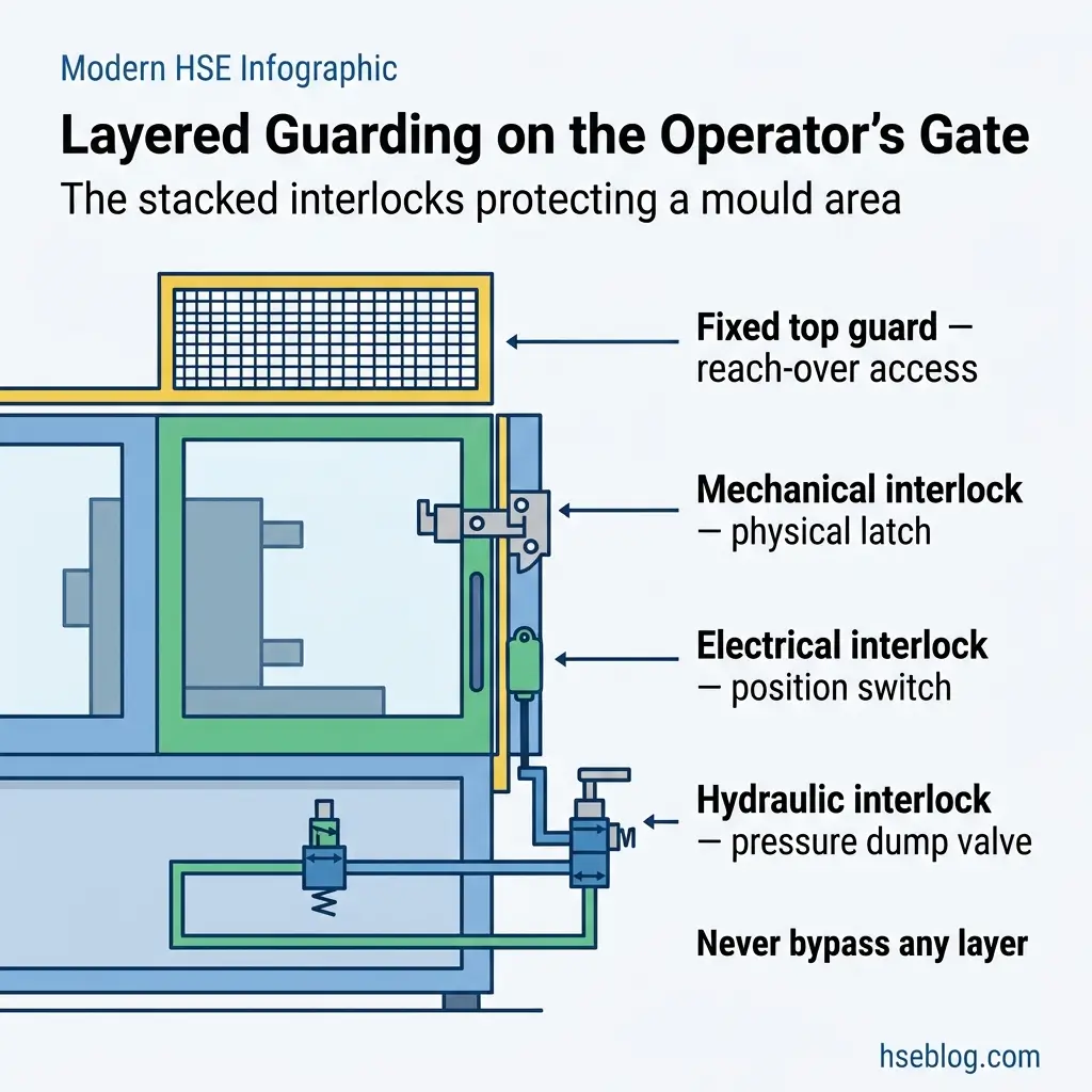
A properly guarded gate does not rely on one interlock. On hydraulic machines, the accepted arrangement layers independent systems so that a single failure cannot leave the clamp live:
- Mechanical interlock — a physical latch or arrester that prevents clamp movement while the gate is open.
- Electrical interlock — a position switch that removes the signal to close when the gate is not fully shut.
- Hydraulic interlock valve — a valve that dumps or blocks clamp pressure so the platen cannot close, independent of the electrical system.
The OSHA plastics-machinery eTool describes exactly this redundancy for horizontal machines, and its logic is worth internalising: interlocks fail, and defence in depth assumes they will. Where a person can stand on the floor and reach over the top of the machine into the mould area, a fixed or interlocked top guard is required — a gap the frame alone rarely closes on larger machines.
The most persistent misconception on the floor is that a working gate makes the mould area safe to reach into. It does not. The gate makes the mould area safe while the interlocks are intact and unbypassed — and the moment someone props, tapes, or defeats a switch to keep production running, every layer collapses at once. That is not a hypothetical: the published incident record is dominated by people reaching in to free a stuck part with the interlocks removed or overridden.
Guarding the clamp mechanism, nozzle, and feed throat
Beyond the front gate, three further zones need dedicated safeguards, and each uses a different logic. A small table clarifies what guards which hazard, because mixing them up is where machines end up under-protected.
| Danger zone | Guard | What it prevents |
|---|---|---|
| Rear of clamp mechanism | Fixed or interlocked rear (setter’s) guard | Access to moving platen and toggle links |
| Nozzle / injection point | Interlocked purge or nozzle guard with position sensor | Molten-plastic splatter and crush between nozzle and platen |
| Feed throat / hopper | Fixed grille or interlocked hopper | Hand contact with the rotating screw |
| Top of machine | Fixed or interlocked top guard | Reach-over into the mould from floor level |
The rear guard matters because setters and maintenance staff work behind the machine where the operator’s gate offers no protection. UK HSE guidance for injection moulding machines is specific here: the interlocked front and rear guards must also prevent access to the clamping mechanism, and the guard should open only after platen movement is complete — with an arrester bracket fitted where a guard could otherwise open faster than the platen retracts.
The nozzle guard carries a subtlety worth flagging. Its position sensor must fail to safety and resist casual defeat, and it should still allow controlled purging outside the guarded area through a manual, reduced-speed facility. That combination — protection during normal running, a safe route for the one task that must happen at the nozzle — is where cheaper installations cut corners.
The mechanical safety device, historically a drop bar or “jam bar” that physically blocks the platen, deserves a note because the requirement genuinely diverges by jurisdiction. Under the US ANSI/PLASTICS B151.1-2017 standard, that device became optional for horizontal machines built to the 2017 edition, on the basis that modern control-system reliability can deliver equivalent protection — a change confirmed when the standard was published (Plastics Industry Association). In practice, many operators outside that framework, and many older machines, still rely on the physical device, so do not assume its absence is compliant everywhere.
Which standards and regulations govern injection moulding machine guarding
The governing framework depends entirely on where the machine operates and who supplied it, and conflating the systems leads to compliance gaps. There is no single global rulebook — there is a family of overlapping ones.
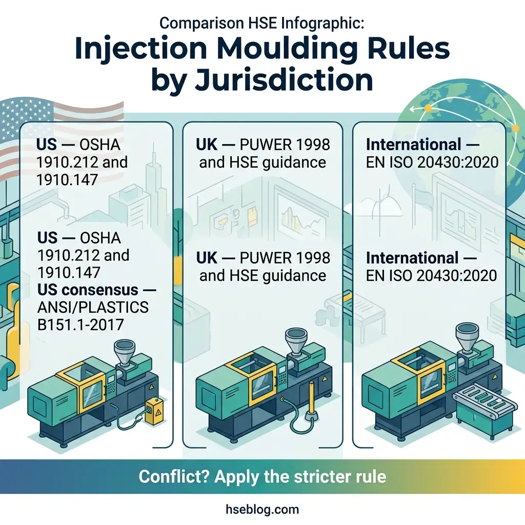
The three that matter most break down by jurisdiction:
- United States (OSHA): 29 CFR 1910.212 sets the general machine-guarding duty, including point-of-operation protection, and 29 CFR 1910.147 governs the control of hazardous energy for servicing and maintenance. ANSI/PLASTICS B151.1-2017 is the consensus standard that specifies how those duties are met on injection moulding machines.
- United Kingdom: The Provision and Use of Work Equipment Regulations 1998 (PUWER), supported by the HSE guidance sheet on injection moulding machines, sets the legal duty; supply of new machinery is governed by the Supply of Machinery (Safety) Regulations 2008.
- International / EU: EN ISO 20430:2020 specifies the essential safety requirements for the design and construction of injection moulding machines, addressing the mould area, clamp mechanism area, whole-body access, and thermal hazards, with guard interlock performance judged against the machinery-control standards it references.
A freshness point is worth building in. EN ISO 20430:2020 superseded the older EN 201 standard, and as of 2026 the US ANSI/PLASTICS B151.1 standard is being reviewed to align with ISO 20430 (Plastics Industry Association) — meaning the transatlantic gap in requirements, including on the mechanical safety device, is narrowing rather than widening.
Where standards conflict, the more protective requirement is the safer default. If your machine could fall under both a permissive and a stricter regime — a US-built machine operating in Europe, for instance — build to the stricter interlock and guarding requirement and document the decision.
This regulatory content reflects general HSE professional understanding of the cited jurisdictions’ requirements as of 2026. It is not legal advice. Specific compliance questions, enforcement situations, or prosecution risk should be directed to qualified legal counsel in the applicable jurisdiction.
Lockout/tagout: where the serious injuries actually happen
Normal production is comparatively well protected; servicing and maintenance is where people lose limbs. The pattern is so consistent that it should reshape how a plant thinks about risk on these machines.
The core error is treating an interlock as an isolation. An interlocked guard is designed to stop a machine that is running — it is not designed to hold a machine safe while someone puts their body into the mould area, changes a mould, or clears a fault. For that, the machine’s hazardous energy must be locked out.
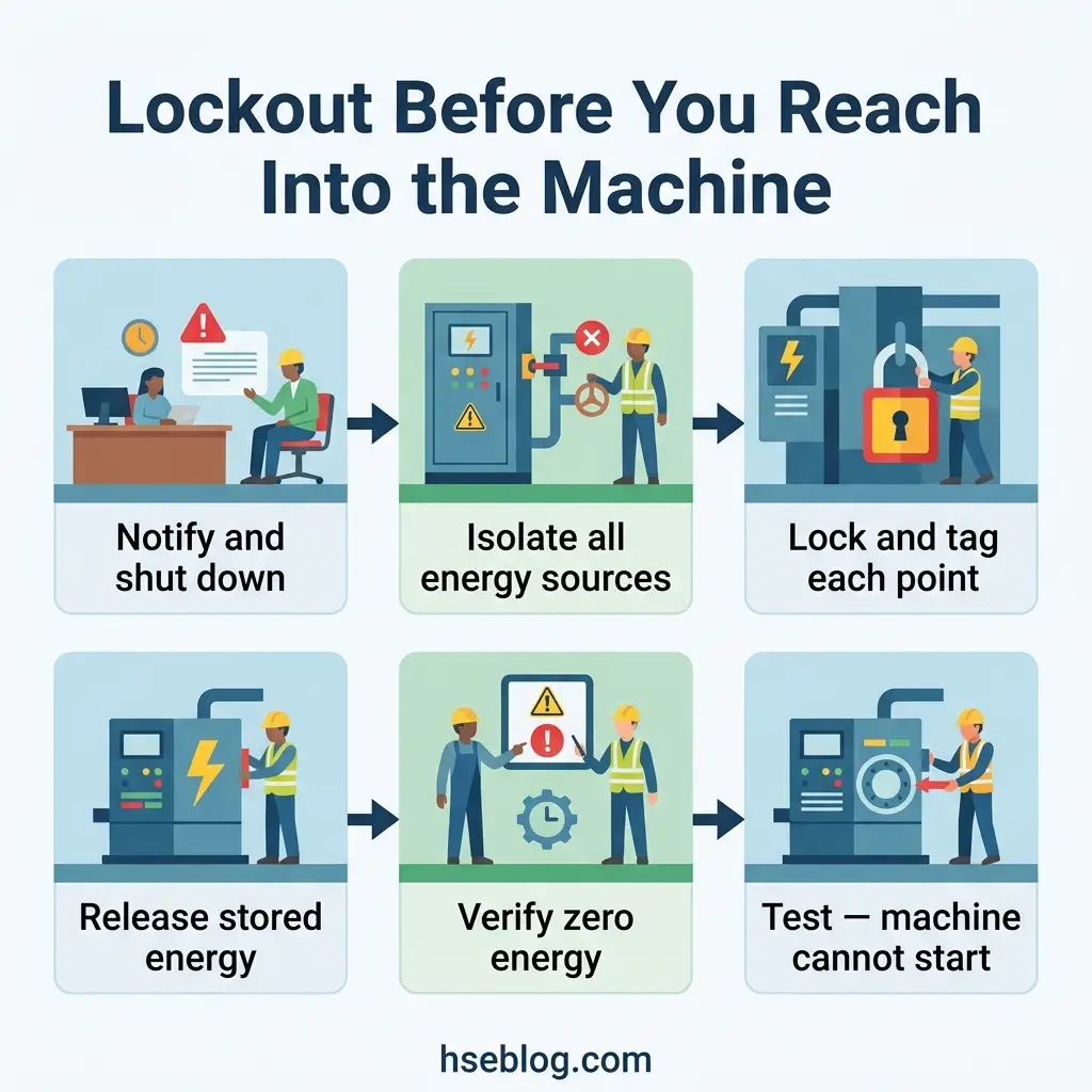
A defensible lockout sequence for mould changes, fault clearing, or repairs runs in order:
- Notify affected operators that the machine is coming down for service.
- Shut down the machine through its normal controls.
- Isolate every hazardous energy source — electrical, hydraulic, and any stored pneumatic or gravitational energy in the clamp or ejector.
- Lock and tag each isolation point with individually keyed devices.
- Release stored energy and verify zero energy before any body part enters a danger zone.
- Test by attempting a normal start to confirm the machine cannot cycle.
One judgment call recurs in practice: the boundary of the minor-servicing exception. OSHA’s hazardous-energy standard allows limited routine, repetitive tasks integral to production to proceed without full lockout only where effective alternative protection exists — and reaching into the mould area or removing a guard falls outside that narrow allowance every time. The safe reading on most sites is that if the task needs a hand past a guard, it needs a lockout.
This distinction is not academic. It is the difference between a machine that stops when a guard opens and a machine that cannot start at all — and that gap is exactly where an unexpected cycle finds an unprotected hand.
Building a guarding-inspection routine that actually catches failures
Guards degrade silently, so the safeguard behind every other safeguard is a routine that finds a defeated interlock before a person does. This is where paperwork earns its place — not as a compliance ritual, but as the mechanism that keeps the earlier controls real.
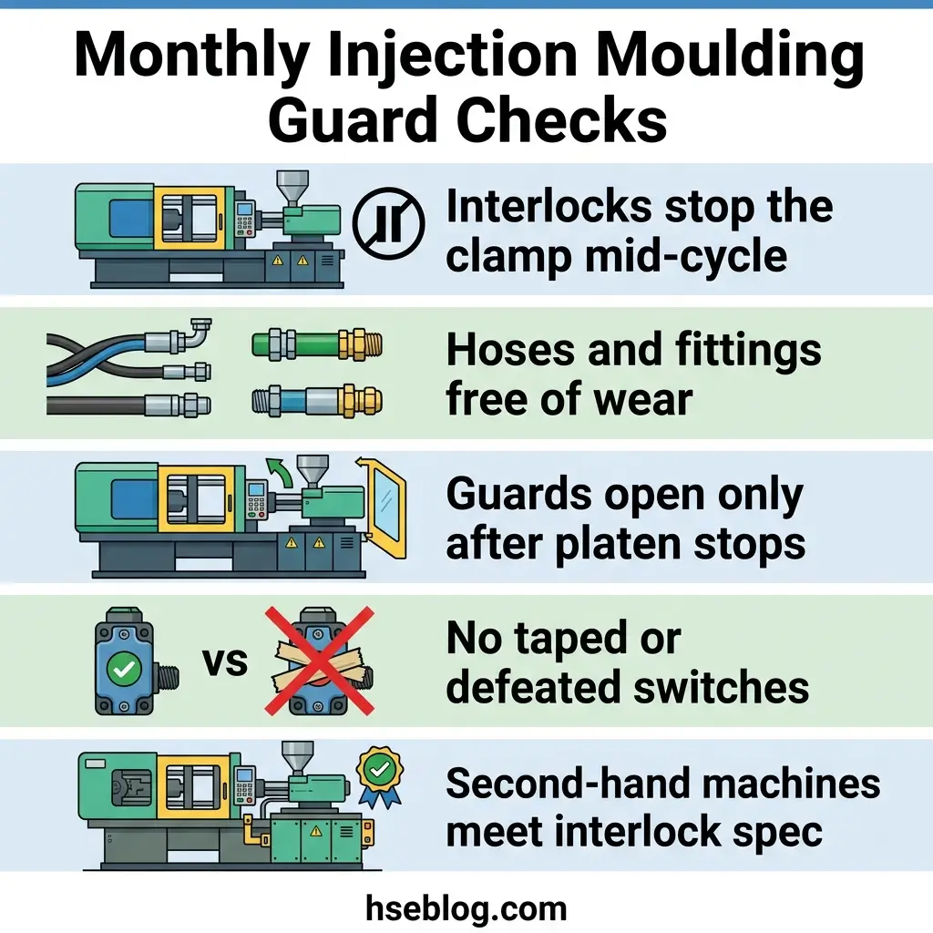
A monthly functional check, cross-referenced against the machine manufacturer’s manual, should confirm the guards do what they claim:
- Test each interlock by opening the gate mid-cycle and confirming clamp motion stops — not just that a light changes.
- Inspect hoses and fittings for wear, fraying, or leaks, and replace on the manufacturer’s schedule rather than on failure.
- Check the nozzle and rear guards open only after platen movement completes, and that position sensors are intact and undefeated.
- Look for signs of defeat — tape, wedges, wired-back switches, or missing top guards where reach-over is possible.
- Confirm second-hand machines meet current interlock performance, an area where imported or resold equipment frequently falls short.
That last point is not theoretical. UK product-safety authorities have issued recall action on injection blow-mould machinery for inadequate guarding of moving parts in the mould area, directing users to risk-assess the equipment and pay particular attention to the performance level of any interlock switches present (Office for Product Safety and Standards). Older and second-hand machines are the population most likely to hide these gaps.
This article provides general HSE knowledge. Life-critical work such as mould changes and maintenance on injection moulding machines must be planned and supervised by a competent person with relevant training, jurisdiction-specific authorisation, and site-specific risk assessment. The information here does not replace that. Structured training through recognised pathways — NEBOSH, IOSH, OSHA outreach programmes, or the regional equivalent — is the route to that competence.
Frequently Asked Questions
Conclusion
Injection moulding machine safety comes down to a handful of decisions made well and enforced consistently. Match each danger zone to its guard — layered interlocks on the operator’s gate, a fixed or interlocked rear guard for the clamp, a fail-safe nozzle guard, and a grille or interlock at the feed throat — rather than assuming one safeguard covers the machine.
Treat the line between an interlock and a lockout as the most important boundary on the floor. When a task needs a hand past a guard, the machine’s electrical, hydraulic, and stored energy must be isolated, locked, and verified at zero before anyone reaches in. That single rule prevents the maintenance injuries that dominate the amputation record.
Then keep the guards honest. A monthly functional check that actually opens the gate mid-cycle, inspects hoses, and looks for defeated switches is what turns a well-specified machine into a safe one — and confirming interlock performance on older and second-hand machines is where that routine pays off most.