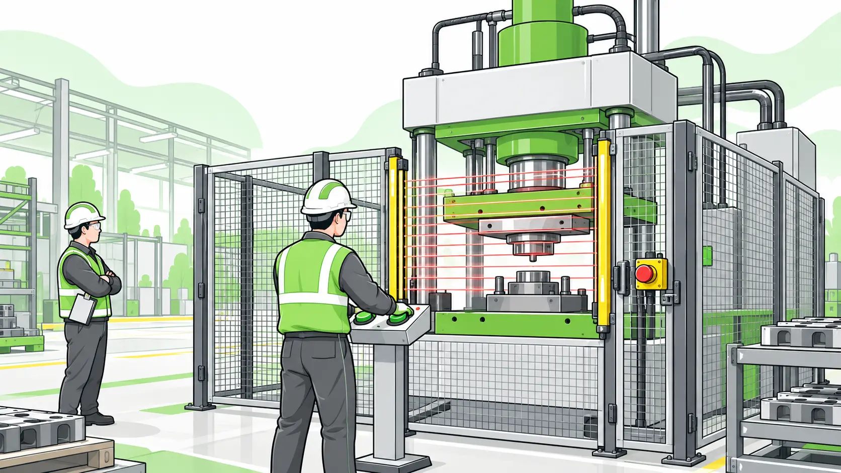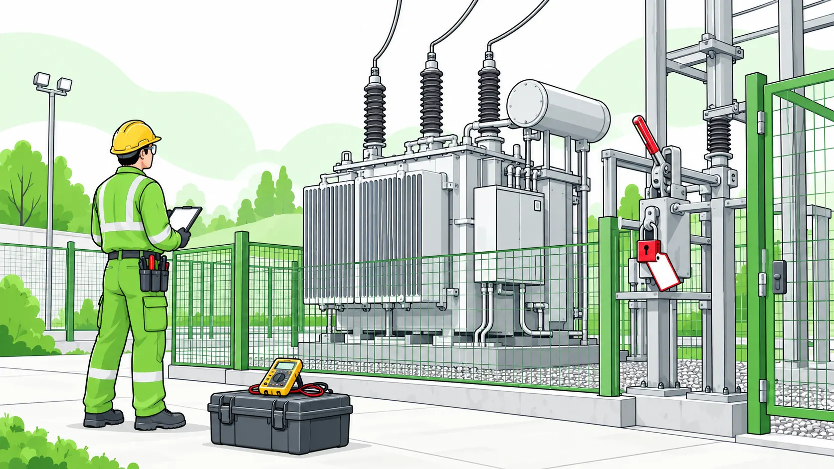
Transformer safety means controlling three overlapping hazards: high-energy electrical (shock and arc flash), fire and explosion from insulating oil, and chemical or environmental release. The core rule is to de-energize, lock out, and verify zero energy before any work — performing only justified energized tasks under a permit and competent supervision.
Electrical contact kills around 150 workers a year in the United States, and the electrical fatality data compiled by ESFI carries a detail that should change how facilities think about their substations: across 2011–2023, about 74% of those deaths were among workers who were not electricians (ESFI, 2025). The people approaching a transformer are very often the ones least trained to read it.
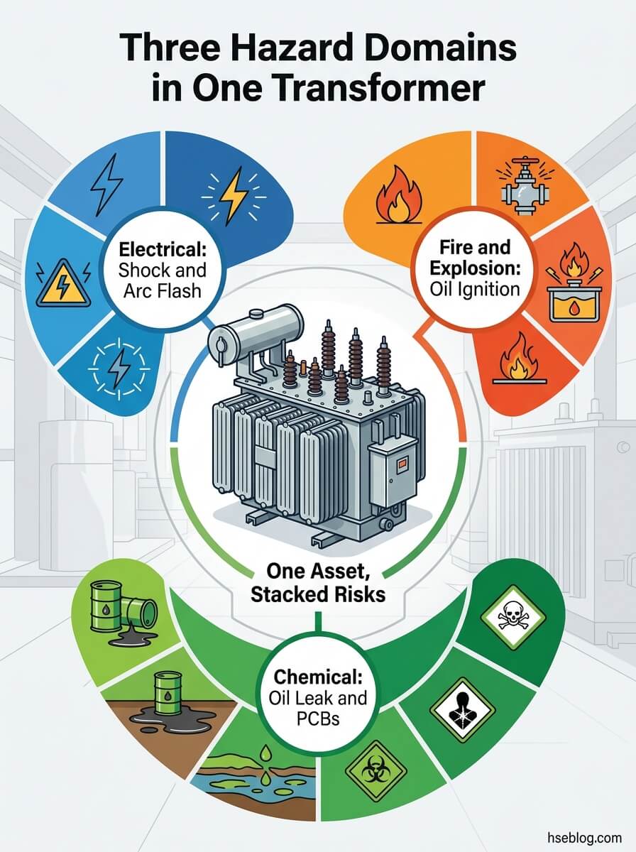
That gap is the reason transformer safety deserves more rigor than ordinary electrical work. A distribution transformer concentrates stored and through-fault energy, holds combustible dielectric oil, and may carry legacy contaminants — three hazard domains stacked in one grey box that most sites leave untouched for decades. This article maps each of those risks to its mechanism, then walks the maintenance and isolation procedures that contain them, with the controlling clauses set side by side across US, UK, and international regimes. Scope note: this covers facility and industrial oil-filled and dry-type units, not utility transmission linework and not homeowner guidance.
Why Transformer Safety Demands a Higher Standard Than General Electrical Work
The single most important fact about transformer risk is who gets hurt: about 74% of electrical workplace deaths from 2011–2023 fell on non-electrical workers (ESFI, 2025). Facility staff, mechanical technicians, and operators routinely stand within feet of energized switchgear they were never trained to interpret.
Transformers earn their elevated risk profile because they pool energy that ordinary equipment does not. Three traits set them apart:
- Concentrated energy. A transformer stores and passes fault energy that, on failure, releases far faster than a worker can react. The probability is low; the consequence is not.
- Combustible fluid. Oil-immersed units hold mineral dielectric oil — an insulator that is also a fuel once a fault breaches containment.
- Legacy chemistry. Units installed before PCB phase-outs may still hold regulated contaminants, turning an oil leak into a reportable environmental event.
These three domains — electrical, fire-explosion, and oil-environmental — form the spine of everything below. A control that fixes one does not necessarily touch the others.
There's a pattern worth naming early. Across the published record and in routine practice, transformers get treated as set-and-forget infrastructure for twenty or thirty years until a fault forces attention. The dangerous window isn't installation or decommissioning, when scrutiny is high — it's the unmonitored mid-life, when nothing seems wrong and nobody is looking.
The Core Risks: What Actually Goes Wrong With Transformers
Most transformer incidents trace back to one of three mechanisms — arc energy, oil combustion, or thermal and environmental degradation — and the controls for each differ. Naming the hazard is not the same as understanding how it harms, so each subsection below runs mechanism first, then why it matters.
Electrical Hazards: Shock, Electrocution, and Arc Flash
Shock and arc flash are different events with different drivers. Shock depends on voltage and the path current takes through the body; arc flash depends on available fault current and the incident energy released when current jumps an air gap.
- Arc flash vaporizes conductor metal and superheats the surrounding air, producing a thermal and pressure event. OSHA's guidance on protecting employees from arc-flash hazards (OSHA 4472) links the regulatory duty to the NFPA 70E and IEEE 1584 methods used to quantify it.
- Arc blast is the pressure wave and shrapnel that can accompany a high-energy arc — a mechanical injury mechanism, not a burn.
- Shock from "dead" equipment. Under OSHA 29 CFR 1910.333(b), parts that have been de-energized but not yet locked and verified must be treated as live. The conductor doesn't know your intentions.
Why it matters: incident energy, not voltage alone, determines how severe an arc flash is. A modest-voltage transformer fed by a high-fault-current source can still produce a life-altering event.
Fire and Explosion: The Oil-Filled Failure Mode
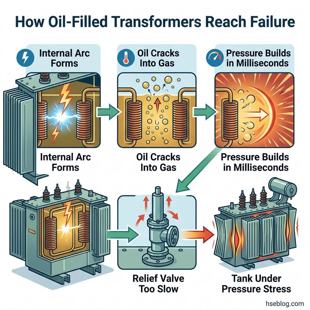
Oil-immersed transformers carry an explosion mechanism that dry-type units do not. An internal fault arcs inside the tank, the arc cracks the oil into combustible gases, and the resulting pressure wave can build faster than mechanical relief valves can vent it.
That millisecond timescale is the whole problem. Pressure-relief devices are sized for normal thermal expansion, not for a fast internal arc, so a severe fault can rupture the tank before relief operates. Serious in-service fires remain rare — on the order of 0.06%–0.1% per service year, or roughly one per 1,000–1,500 transformer service-years (Transmission & Distribution World, cited 2024) — but "rare" is not "controlled."
Dry-type units lower this risk because there is no oil to ignite or release. They do not eliminate it: the full electrical and arc-flash hazard remains.
Thermal, Mechanical, and Environmental Hazards
The slow-burn risks rarely make headlines but feed the dramatic ones. Overload and overheating degrade insulation; degraded insulation invites the internal fault that becomes a fire.
- Overheating and overload accelerate insulation aging and gas generation inside the tank.
- Oil leaks are both a slip and contamination hazard and, for legacy units, a regulated release. PCB-containing oil at or above 50 ppm triggers controlled handling under EPA 40 CFR 761 (TSCA) in the US.
- Noise and mechanical stress from loose cores or failing tap changers often precede electrical faults.
Note on PCB and oil exposure: content here is for HSE practitioner reference and is not medical advice. Workers with specific exposure concerns should consult an occupational physician.
A consistent failure signature across the record is organizational, not technical: a changed hum, a fresh oil seep, or a breaker that tripped and got reset are dismissed as nuisance rather than escalated as the early voice of an internal fault. The detection often exists. The decision to act on it doesn't.
Maintenance Procedures: Building a Defensible Transformer Maintenance Program
Since January 2023, the question "how often should we service this?" has a different answer than it used to. NFPA 70B converted from a recommended practice to a mandatory-language standard, moving electrical equipment maintenance from "should" to "shall" and tying intervals to equipment condition rather than the calendar (ESFI/NFPA, 2023).
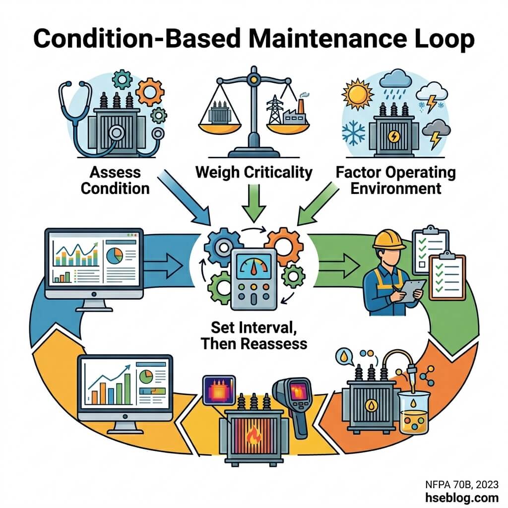
That shift reshapes transformer maintenance procedures around three tiers, not a fixed schedule.
| Tier | Purpose | Typical activities |
|---|---|---|
| Preventive | Stop known degradation | Visual checks, cleaning, gasket and bushing inspection, oil level/temperature |
| Predictive | Catch faults before failure | Infrared thermography, dissolved gas analysis, partial discharge testing |
| Corrective | Restore after a defect is found | Repair, component replacement, oil reconditioning |
Establishing an Electrical Maintenance Program (and Why It's Now Mandatory Language)
The headline change is condition-based scoping. NFPA 70B (2023) bases maintenance intervals on an Equipment Condition Assessment combining physical condition, criticality, and operating environment — and the conservative reading is to let the worst of the three set the interval.
This is a US consensus standard, not statute. The practical catch is that OSHA can cite it as the recognized benchmark for a maintained system, so "it's only NFPA" is a weaker defense than duty-holders assume.
Routine Inspection and Condition Monitoring
Routine work splits cleanly by competence. Unqualified facility staff can observe and report; qualified persons interpret and intervene.
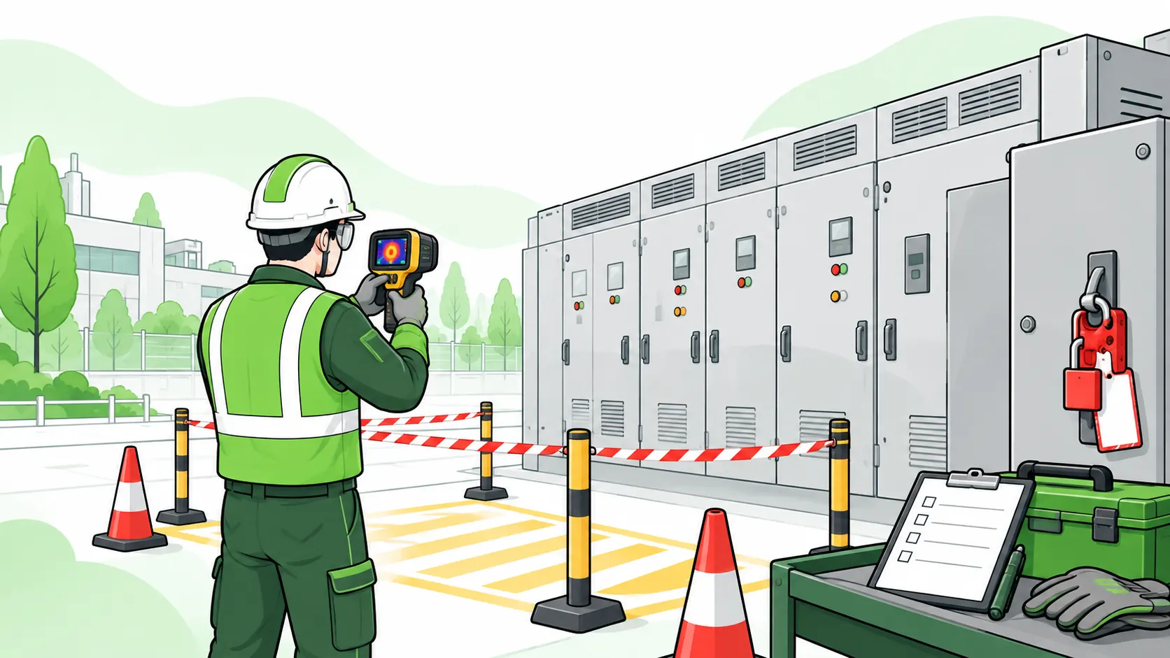
- Open to facility staff: logging temperature and oil-level gauges, noting visible leaks, listening for changed hum, flagging discoloration or corrosion.
- Qualified-person only: infrared thermography under load, bushing and tap-changer assessment, anything inside the enclosure or near energized parts.
The line matters because an untrained observer who opens a panel to "check" has just crossed from monitoring into energized exposure.
Oil Testing and Dissolved Gas Analysis (DGA)
DGA is the diagnostic backbone for oil-filled units because the oil records the fault before the transformer fails. Specific fault gases point to specific problems — hydrogen and acetylene suggest arcing, ethylene suggests overheating.
A current development is reducing on-site risk: online and continuous DGA monitoring, using in-situ sensors, is shifting diagnostics from periodic sampling toward real-time fault detection (peer-reviewed review, NCBI/PMC, 2019–2025). Less manual sampling means less exposure to flammable fault gases.
The recurring program failure here is subtle. Teams collect DGA reports and file them as single snapshots, but the diagnostic value lives in the rate of change between samples — without a baseline and a trend, the test loses the exact early-warning signal it exists to provide.
How to Safely De-Energize and Work on a Transformer
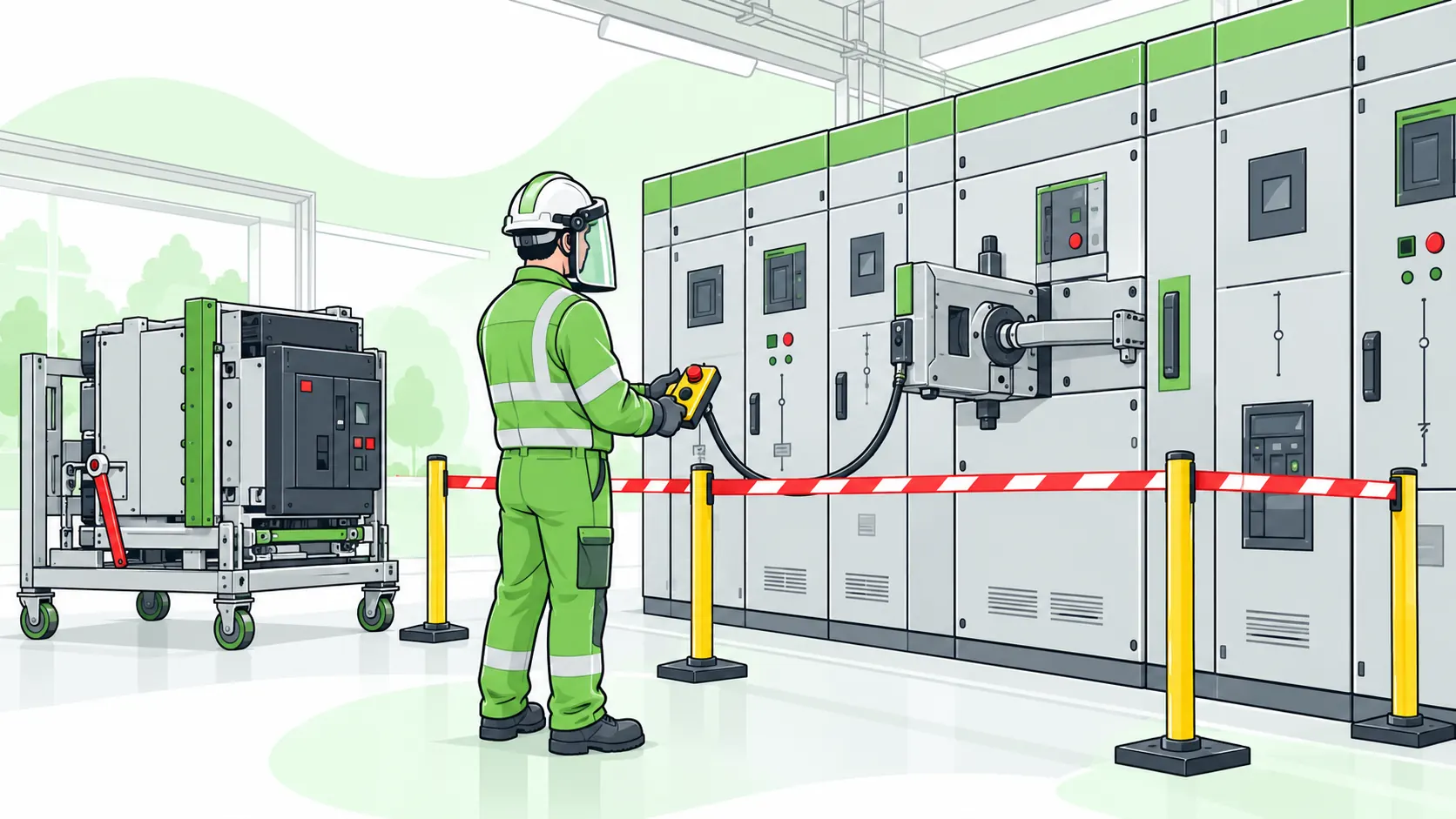
The default for transformer work is simple to state and hard to shortcut: de-energize, isolate, and verify zero energy before touching anything. Energized work is the exception, not the starting point.
Competent-person and jurisdiction caveat: This section describes the electrically-safe-work-condition concept at a conceptual level. Life-critical work such as transformer de-energization, LOTO, and any energized-work decision must be planned and supervised by a competent person with relevant training, jurisdiction-specific authorization, and a site-specific risk assessment and arc-flash study. This information does not replace site procedure, manufacturer instructions, or that supervision.
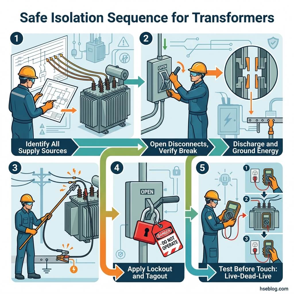
The conceptual sequence runs:
- Identify all sources of supply. Transformers can be back-fed; one open disconnect is rarely the whole picture.
- Open the disconnecting means for every identified source.
- Visually verify the break where the design allows.
- Discharge and ground stored energy.
- Apply lockout/tagout under OSHA's lockout/tagout standard (29 CFR 1910.147), with only authorized employees applying and removing their own locks.
- Test before touch using a meter proven live → dead → live on a known source.
The step most often compromised under time pressure is the last one. "I locked it out" and "I verified zero energy" are not the same statement, and collapsing the two is a documented failure mode. A device de-energized but not yet verified must be treated as live — exactly the position OSHA 1910.333(b) takes.
Energized work, when truly unavoidable, becomes a justified exception requiring an energized-electrical-work permit and risk assessment under NFPA 70E (2024) in the US, and the equivalent live-working test under the UK's Electricity at Work Regulations. Training pathways that build this competence include NEBOSH, IOSH, and OSHA outreach programs, plus recognized regional equivalents.
PPE and Approach Boundaries for Transformer Work
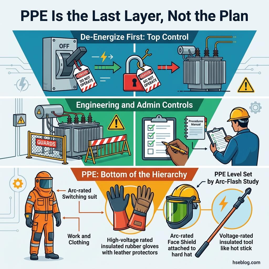
PPE is the last layer, not the plan. It protects against residual energy after de-energization fails or cannot be achieved — never the primary control.
That ordering comes straight from the hierarchy of controls: elimination through de-energization always outranks protection. PPE sits at the bottom precisely because it depends on a human wearing it correctly every time.
The protective kit for justified energized transformer work generally includes:
- Arc-rated clothing matched to the calculated incident energy, not a generic guess.
- Insulated gloves, rated and within their test cycle, with leather protectors.
- Face and eye protection — arc-rated face shield or hood per the hazard level.
- Voltage-rated, insulated tools for any work near energized parts.
The decisive point is that approach boundaries and PPE levels derive from a site-specific arc-flash study, not a one-size table. A frequent and dangerous error is treating a blanket "Category 2" assumption as universal. Incident energy is specific to each installation, and an arc-flash label goes stale the moment the upstream system changes — a new transformer, altered breaker settings, or a revised feeder all invalidate the old number.
Regulatory and Standards Landscape: US vs UK vs International
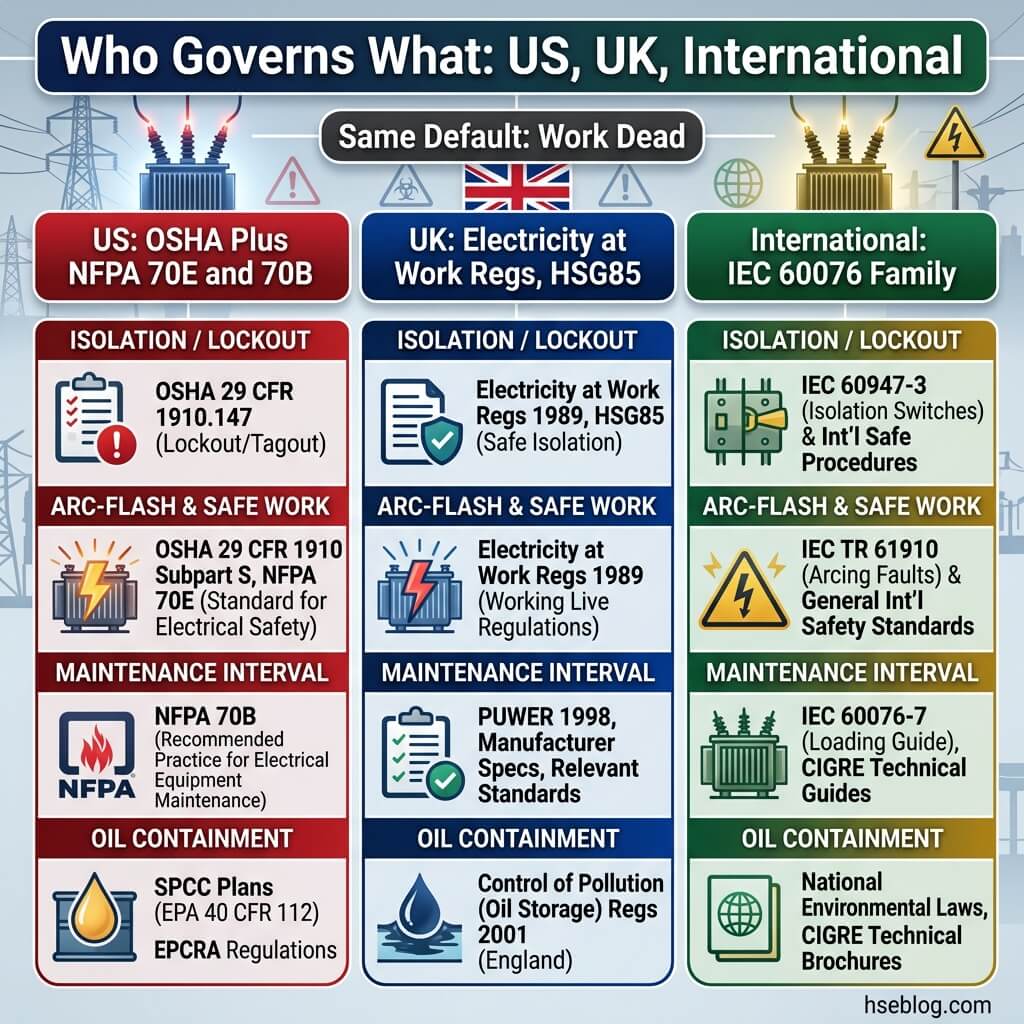
A reader operating in either the US or UK needs to know which instrument governs each procedure — and the regimes reach the same default (work dead) by different legal routes. The practical-first reading is that isolation, safe work, maintenance, and oil containment each map to a specific instrument per jurisdiction.
Legal disclaimer: Regulatory content here reflects general HSE professional understanding of US and UK requirements as of 2025. It is not legal advice. Specific compliance questions, enforcement situations, or prosecution risk should be directed to qualified legal counsel in the applicable jurisdiction. Regulatory content was last reviewed [Month YYYY — to be filled at publish].
| Procedure | US (OSHA + NFPA) | UK (HSE) | International / EU |
|---|---|---|---|
| Energy isolation / LOTO | 29 CFR 1910.147 | EAWR 1989, regs 12–13; HSG85 | ILO frameworks |
| Safe work / arc flash | NFPA 70E (2024); OSHA 1910.331–335, .269 | EAWR 1989, reg 14; HSG85 / HSR25 | IEC arc-protection standards |
| Maintenance scope/interval | NFPA 70B (2023) | EAWR duty to maintain | IEC 60076 family |
| Oil spill containment | EPA 40 CFR 112 (SPCC) | UK oil-storage and pollution rules | Varies |
| PCB handling | EPA 40 CFR 761 (TSCA, ≥50 ppm) | UK PCB regulations | Stockholm Convention |
Two interpretive points carry the synthesis. First, US duty-holders often treat NFPA 70E and 70B as "optional" because they aren't statute — missing that OSHA cites them through the General Duty Clause, so the practical obligation is far closer than the legal label suggests.
Second, the regimes align on substance. The UK's "secure isolation from every source" under the Electricity at Work Regulations 1989 — backed by HSE guidance on safe working practices (HSG85) — functions much like OSHA LOTO. The UK reaches the work-dead default through a "reasonably practicable" test; the US reaches it through a permit-based energized-work exception. Different legal mechanics, same physics, same answer.
On thresholds, US containment is explicit: facilities above the SPCC threshold need secondary containment sized to hold at least 110% of the largest container's volume (EPA 40 CFR 112). And on stricter-reference logic — OSHA doesn't prescribe a specific arc-flash calculation method but enforces the hazard duty, so NFPA 70E and IEEE 1584 should govern as the recognized stricter benchmark.
Frequently Asked Questions
How often should a transformer be serviced?
There's no single correct number. NFPA 70B (2023) bases intervals on condition, criticality, and operating environment — take the most demanding of the three. In practice, oil-filled units are commonly sampled annually for DGA, but manufacturer guidance and duty cycle should govern the actual schedule. A heavily loaded transformer in a harsh environment needs attention far sooner than a lightly loaded one indoors.
Why do transformers explode?
Explosions follow an internal fault: arcing inside the tank cracks the insulating oil into combustible gas, and the pressure wave builds faster than relief devices can vent it. The tank can rupture in milliseconds. Critically, this can happen even on a well-maintained unit, which is exactly why early-fault detection through DGA and thermography matters more than the false comfort of a recent service date.
How far should you stay from a transformer that has failed or is on fire?
For bystanders, the common public-safety guidance is to keep well back — frequently cited at roughly 10 metres (30 feet) — and never approach. Never use water on an oil fire, and call the utility and emergency services. This is general bystander guidance and is entirely separate from trained worker procedure, which requires its own controls and competent supervision.
Can you work on a transformer without fully de-energizing it?
The default is always to de-energize. Energized work is a justified exception requiring an energized-electrical-work permit and risk assessment under NFPA 70E (2024) in the US, or the "live working only when unreasonable to work dead" test under the UK Electricity at Work Regulations 1989. Either way, it is competent-person-only work — not a shortcut for time pressure.
Are dry-type transformers safer than oil-filled ones?
Only in specific domains. Dry-type units remove the oil fire, explosion, spill, and PCB risks, which is a real advantage. But they retain the full electrical and arc-flash hazard — a dry-type transformer can still deliver a fatal arc event. The honest comparison is hazard-by-hazard, not a blanket label of "safer."
What's the difference between NFPA 70E and NFPA 70B?
NFPA 70E covers safe work practices for people — arc-flash assessment, safe work conditions, and PPE. NFPA 70B covers maintenance of the equipment itself and became a mandatory-language standard in 2023. They interlock: 70B keeps the equipment in a condition where 70E's protections can hold, and OSHA can reference both. Confusing the two leads sites to maintain people-safety rules while neglecting the equipment.
Conclusion
The industry's recurring mistake with transformers isn't a lack of rules — it's treating detection as the finish line. Sites buy the DGA test, install the gauges, and apply the arc-flash label, then file the data and stop watching. The highest-impact change available to most facilities costs nothing new: act on what the equipment is already telling you, and treat the quiet mid-life years as the period that demands attention rather than the period that earns neglect.
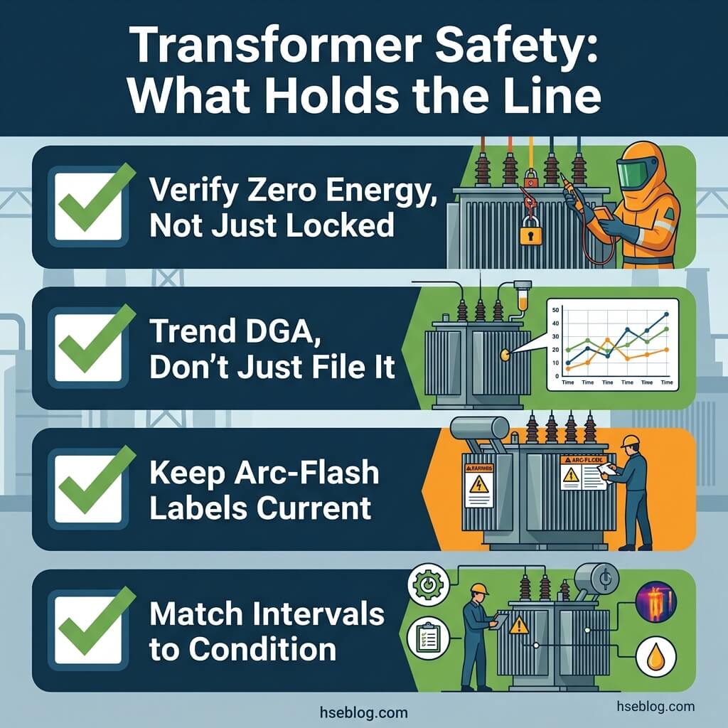
Transformer safety holds together when four habits become non-negotiable. Verify zero energy rather than trusting that a lock equals a dead conductor. Trend DGA results across samples instead of reading them in isolation. Refresh arc-flash labels whenever the upstream system changes. And tie maintenance intervals to condition under NFPA 70B logic rather than a calendar that ignores how hard the unit is actually working.
Whatever jurisdiction you operate under, the physics doesn't negotiate and the default is the same: work dead, verify, and reserve energized work for the rare justified exception under competent supervision. The grey box in the yard has been patient for decades — that patience is exactly what makes it dangerous when it finally isn't.